 | VELOCITY ANALYSIS (ITERATION 2, AUTO PICKING) |
|
<< Click to Display Table of Contents >> Navigation: Tutorials > Seismic Processing 2D LAND >
|
In seismic processing one of the key steps is velocity analysis which is used for compensation of distance between source and receiver. This distance or offset has unwanted influence on travel time, so we need to apply normal move out (NMO) corrections to bring reflections on zero-offset, to make reflection's hodograph flat. Seismic wave speed is usually called velocity, and the estimation process is called velocity analysis. In time processing, we estimate the stacking or migration velocities and in the case of depth imaging, we need to build the velocity model with using different kinds of methods like tomography, FWI and so on.
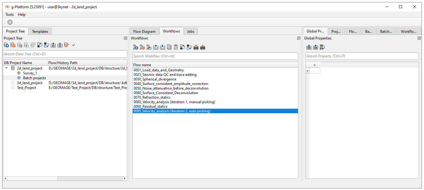
Create a new workflow 0095_Velocity_analysis_(iteration 2, auto picking):
Add all necessary modules:
1. Read seismic traces - load traces after deconvolution step
2. Load item - load refraction static
3. Load item - load residual static
4. Stack imaging - stacking velocity estimation, muting, CMP trace stacking
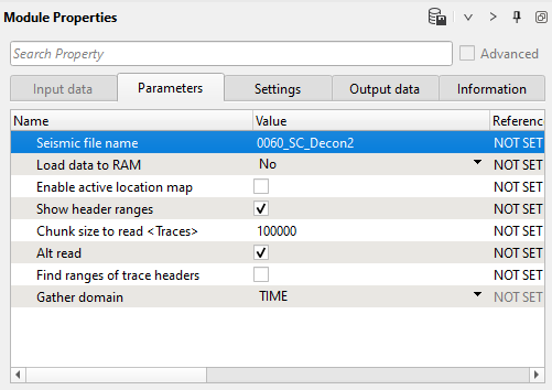
1) Read seismic traces. Define the input seismic file parameter 0060_SC_decon2:
Parameters:
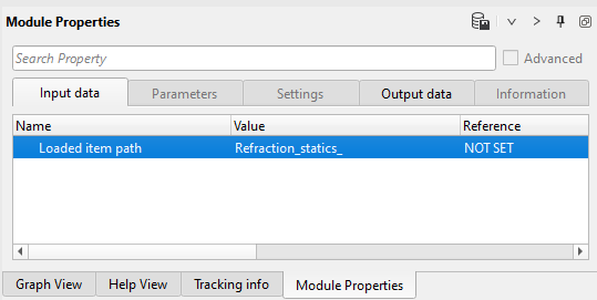
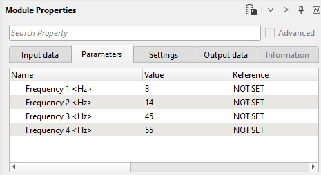
2) Load item - refraction static: load refraction static library from DB. Define an input file name Refraction_statics_:
Parameters:
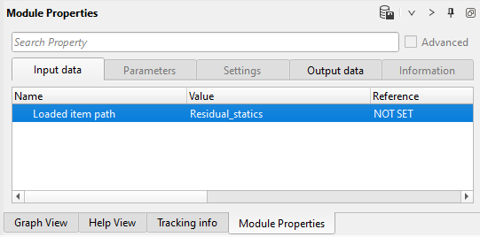
3) Load item - residual static: load refraction static library from DB. Define an input file name Residual_statics:
Parameters:
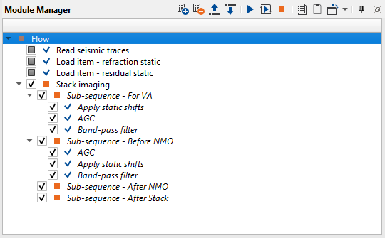
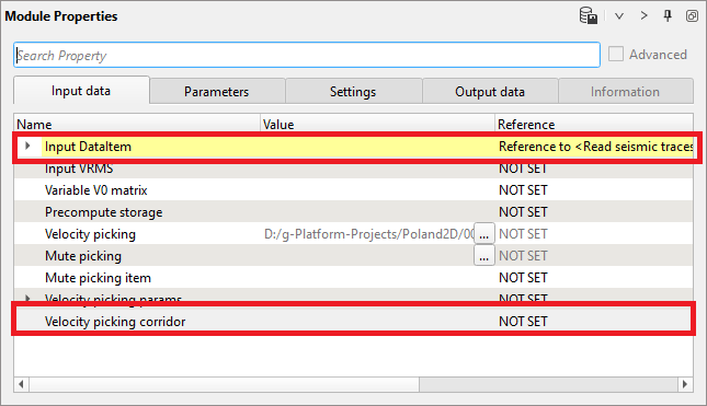
4) Stack imaging. This module is complex interactive application for velocity analysis, creating mute function, stacking CMP gathers. Input data is gathers in any sorting, without NMO corrections. Get input data items from Read seismic traces. Velocity corridor is not required as an input at the beginning however when we execute Velocity auto picking option in Stack Imaging, it will give an error message that velocity picking corridor is required. To avoid that the user should first pick the velocity corridor. Connect Input DataItem and open all necessary vista groups. For example, you can use the following windows: Velocity analysis, Velocity analysis corridor, Location map XY, Current NMO seismogram, Stack inline, Velocity inline.
Input data:
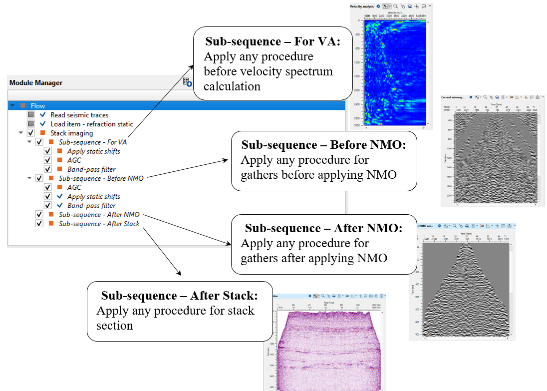
Pay attention on what is inside Stack imaging module, it is sub-sequence. Sub-sequence helps to avoid creating a separate workflow to apply an AGC or Deconvolution or other processing modules, we just simply insert those modules in the sub-sequence inside the main module. Put modules inside the sub-sequence as shown below:
•Sub-sequence - For VA: processing for velocity analysis, i.e. apply some procedures like band-pass or AGC, and then velocity spectrum is calculated;
•Sub-sequence - Before NMO: processing before applying NMO corrections to gathers, for example we can apply static corrections;
•Sub-sequence - After NMO: processing before applying NMO corrections to gathers, for example we can apply denoise procedures;
•Sub-sequence - After Stack: processing after stacking CMP gathers, for example we can apply denoise procedures or spectrum balancing.
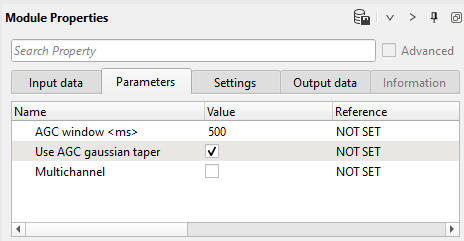
AGC parameters:
Band-pass filter parameters:
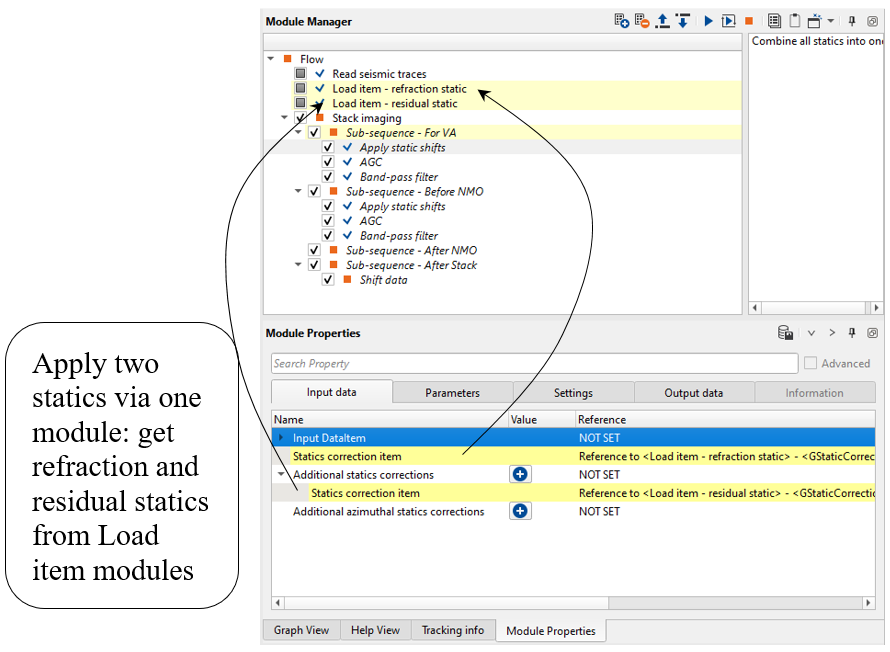
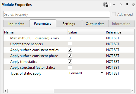
Apply static shifts input data and parameters (Pay attention that we apply two static corrections by one Apply static shifts module):
Normally, when we open all Vista Groups, all visual windows appear, however Velocity analysis corridor is not part of the 2D groups. Therefore, we need to add the vista group Velocity analysis corridor separately as shown below:
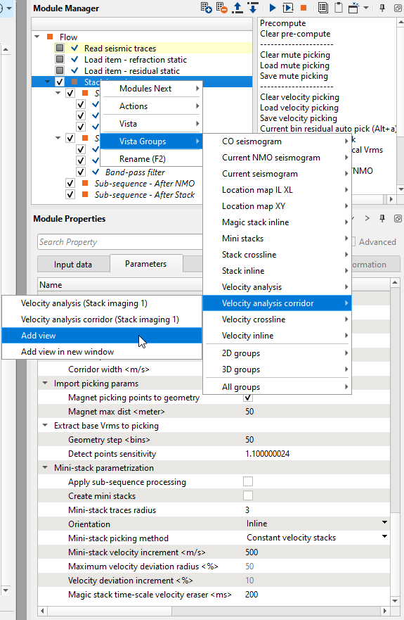
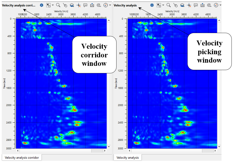
Now it will be added to the existing other Vista items. Velocity analysis and Velocity analysis corridor both look a like however the functioning of each one of them is slightly different. We use Velocity analysis for picking the velocity manually whereas in Velocity analysis corridor, we use it for picking the velocity corridor which is mandatory for picking the velocities automatically.
To pick the velocity corridor,
1. Define auto-picking and corridor semblance parameters. Open parameters tab of the module for automatic picking. As we discussed in previous chapter Velocity analysis (Iteration 1, manual picking), pay attention to the required parameters. In this chapter, we focus on two parameter sections Auto picking and Semb. cube 2D auto picking:
Parameters:
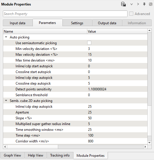
Auto picking:
This part of Stack Imaging module deals with Auto picking of velocities. The user should provide the following parameters.
Use semiautomatic picking - By default it is unchecked. If it is checked, it will do only semi automatic picking of the velocities otherwise it will pick the velocities as per the user defined parameters for the entire line.
Min velocity deviation (%) - Specify how much minimum velocity deviation from the current velocity trend.
Max velocity deviation (%) - Similarly how much maximum velocity deviation from the current velocity trend.
Max time deviation (ms) - Provide the maximum acceptable time deviation. It's time window for single auto-pick.
Inline/cdp start autopick - Specify the starting inline (in case of 3D) or CDP (in case of 2D) number to auto-pick the velocities.
Crossline start autopick - Specify the starting crossline number to auto-pick the velocities.
Inline/cdp step autopick - This parameter is for residual auto picks only. Provide the inline/CDP step size.
Crossline step autopick - Provide the crossline step size for residual auto pick.
Semblance threshold - When Semblance calculation is done, it is either 1 or 0. If the correlation between any two given points is 1 then we have a very good semblance otherwise we have no semblance which means 0. In the case of automatic velocity picking, when the user provides a semblance threshold value of 0.5, then it will ignore picking the velocities anything below 0.5 semblance threshold.
Semb. Cube 2D auto picking:
This is used for auto picking the velocities based on velocity corridor.
Inline/CDP step autopick - This is the main parameter at what interval the automatic velocity picking should be done. If user provides the Inline/CDP step auto-pick as 25, then it will automatically pick the velocities at every 25th Inline/CDP.
Aperture - No of neighboring BINs to analyze the semblance for the current picking location.
Slope (%) - This parameter relates to the reflectors. If the reflectors are straight then the slope can be less otherwise the slope can be a higher value.
Multiplied super gather radius inline - It is number of bins used to analyze the semblance and multiplied by the user defined factor. Higher multiplication factor means less events for auto picking. The higher multiplication factor stabilizes the semblance laterally.
Time smoothing window (ms) - Provide the smoothing window to smooth the velocity function. The larger the smoothing window the smoother the velocity function.
Time step (ms) - Provide the time step at what interval the automatic picking should take place.
Corridor width (m/s) - Define the velocity corridor width.
2. Click on any where on the Stack inline/Velocity inline or Location map and look at Velocity analysis window and Velocity analysis corridor:
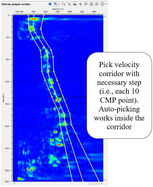
3. Next, go to the Velocity analysis corridor and choose Manual velocity corridor option from the control item ![]() icon. To pick the corridor, just click on the Velocity analysis corridor with MB1 or left mouse button. You will observe 3 lines, it is velocity corridor (left limit, center and right limit). To adjust the corridor picks, we can hold MB1 or LMB and drag the green points wherever we want. Pick velocity corridor by going through different CMP points and check. If the corridor is outside of the velocity semblance we can either pick a new velocity corridor at that particular CMP location or adjust the corridor. We need to pick a skeleton of velocity corridor for auto-picking. Corridor for each CMP point will be automatically interpolated between the two existing corridor picks.
icon. To pick the corridor, just click on the Velocity analysis corridor with MB1 or left mouse button. You will observe 3 lines, it is velocity corridor (left limit, center and right limit). To adjust the corridor picks, we can hold MB1 or LMB and drag the green points wherever we want. Pick velocity corridor by going through different CMP points and check. If the corridor is outside of the velocity semblance we can either pick a new velocity corridor at that particular CMP location or adjust the corridor. We need to pick a skeleton of velocity corridor for auto-picking. Corridor for each CMP point will be automatically interpolated between the two existing corridor picks.
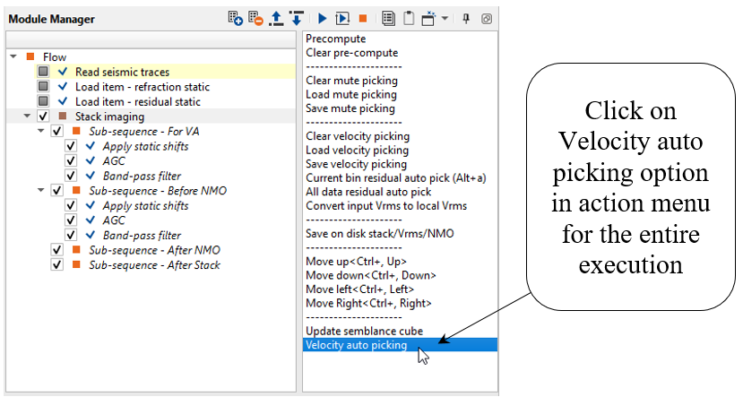
Once we have picked velocity skeleton, now it is time for velocity auto picking. To do that, click on Velocity auto picking action item as shown below:
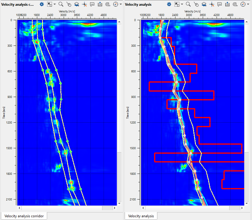
Velocity analysis corridor and Velocity analysis windows after auto-picking process:
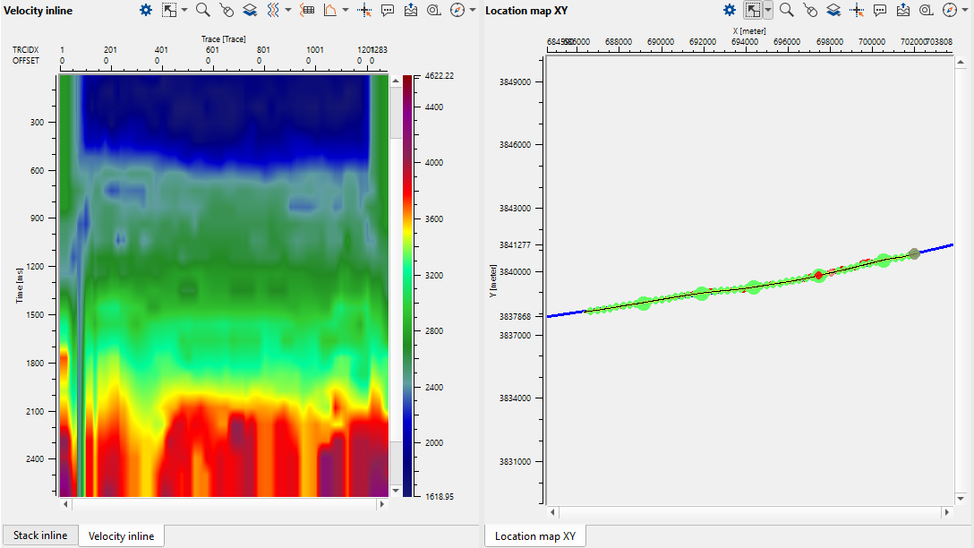
Velocity model and Location map. Velocity is quite sharp, so we will apply smoothing and editing edge effects (caused by low fold):
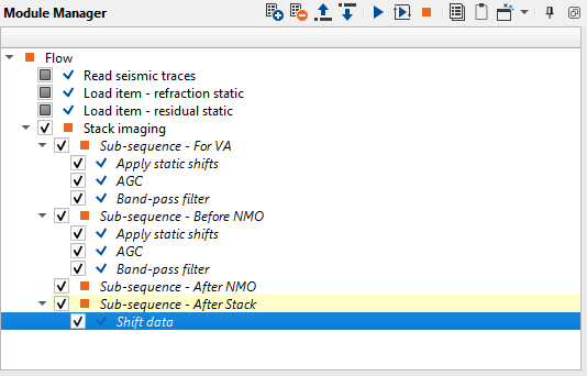
Press the Execute module ![]() icon to rebuild a stack. Now we have a new stack, velocity and mute function for stack. But stack is on stack on floating datum (after NMO applying inside the module), but we need to shift it to the final datum (constant). Add Shift data module to the Sub-sequence - After Stack as shown below:
icon to rebuild a stack. Now we have a new stack, velocity and mute function for stack. But stack is on stack on floating datum (after NMO applying inside the module), but we need to shift it to the final datum (constant). Add Shift data module to the Sub-sequence - After Stack as shown below:
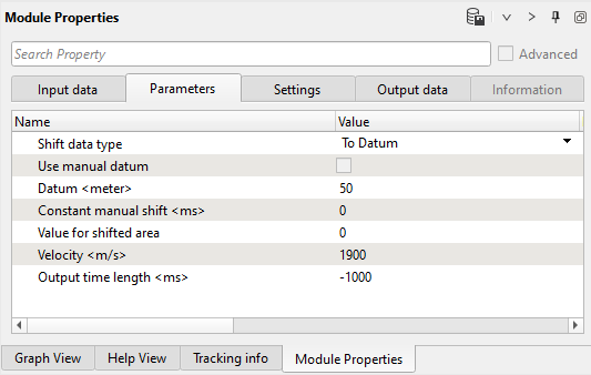
Define Shift data parameters:
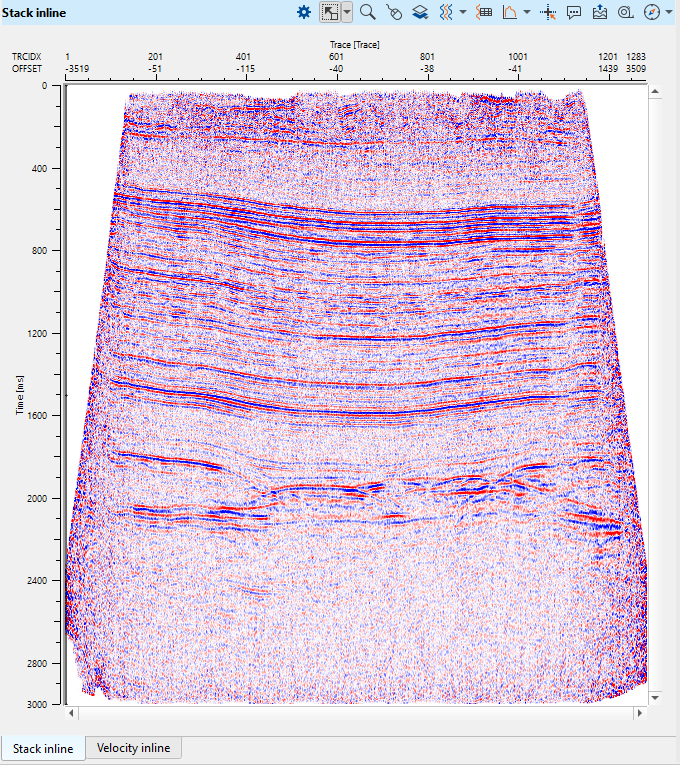
Press the Execute module ![]() icon to rebuild a stack on final constant datum plane:
icon to rebuild a stack on final constant datum plane:
.
Use datum parameter in Stack imaging module instead of using Shift data module inside the Sub-sequence - After Stack
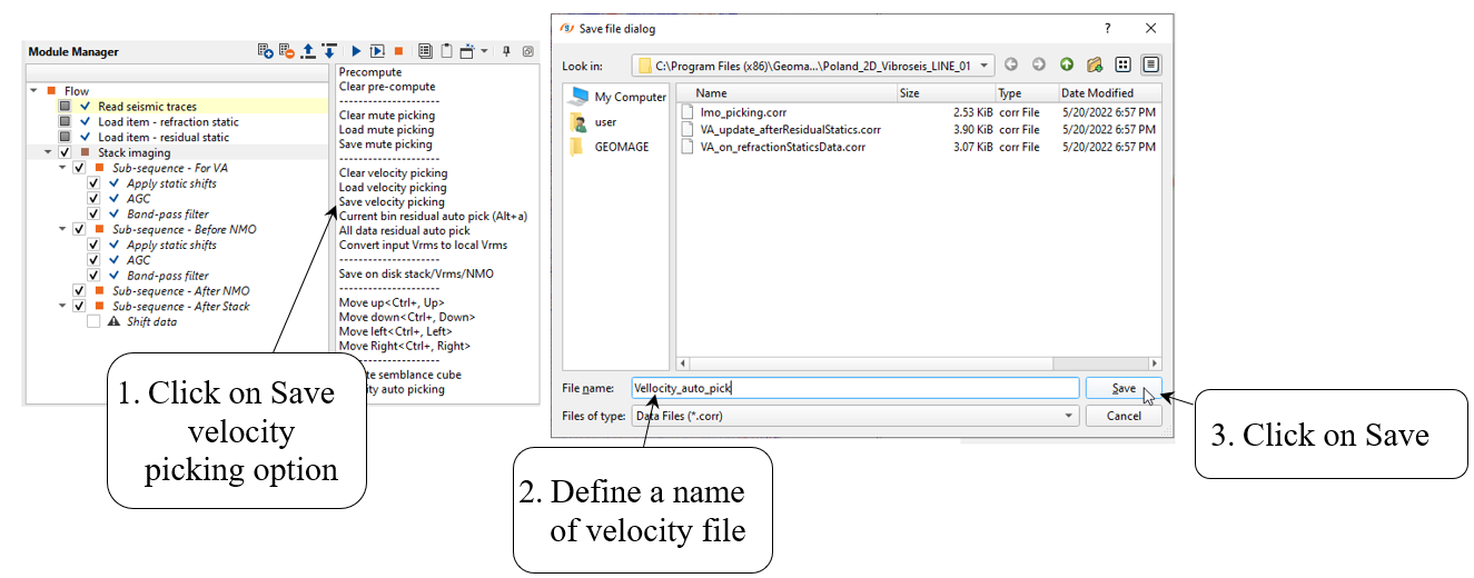
Save final velocity on disk: use action menu-> Save velocity picking -> define a file name for velocity pick file:
Velocity editing:
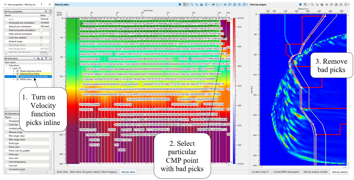
We need to correct edges, open velocity and spectrum windows. Go to the particular CMP point by clicking on picked CMP trace on the velocity stack section (Velocity inline), and correct or remove bad picks:
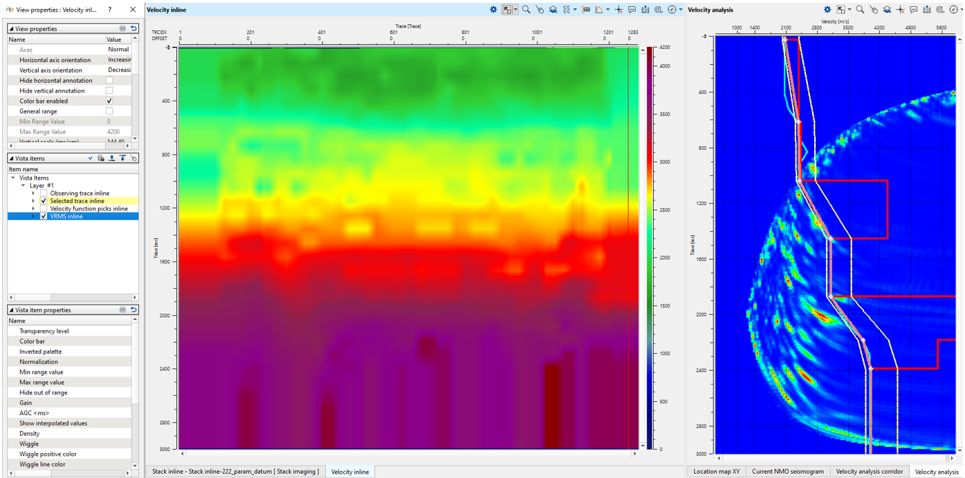
Now we don't have bad picks and need just smooth velocity model:
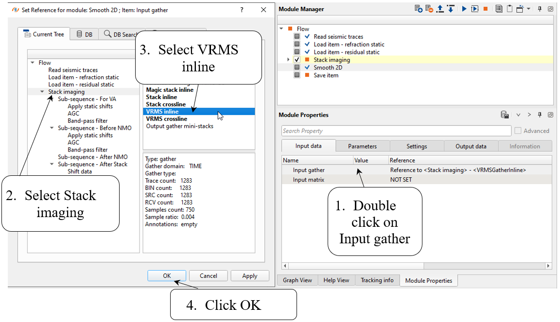
Add Smooth 2D module, define input data and parameters as shown below:
Input data:
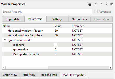
Parameters:
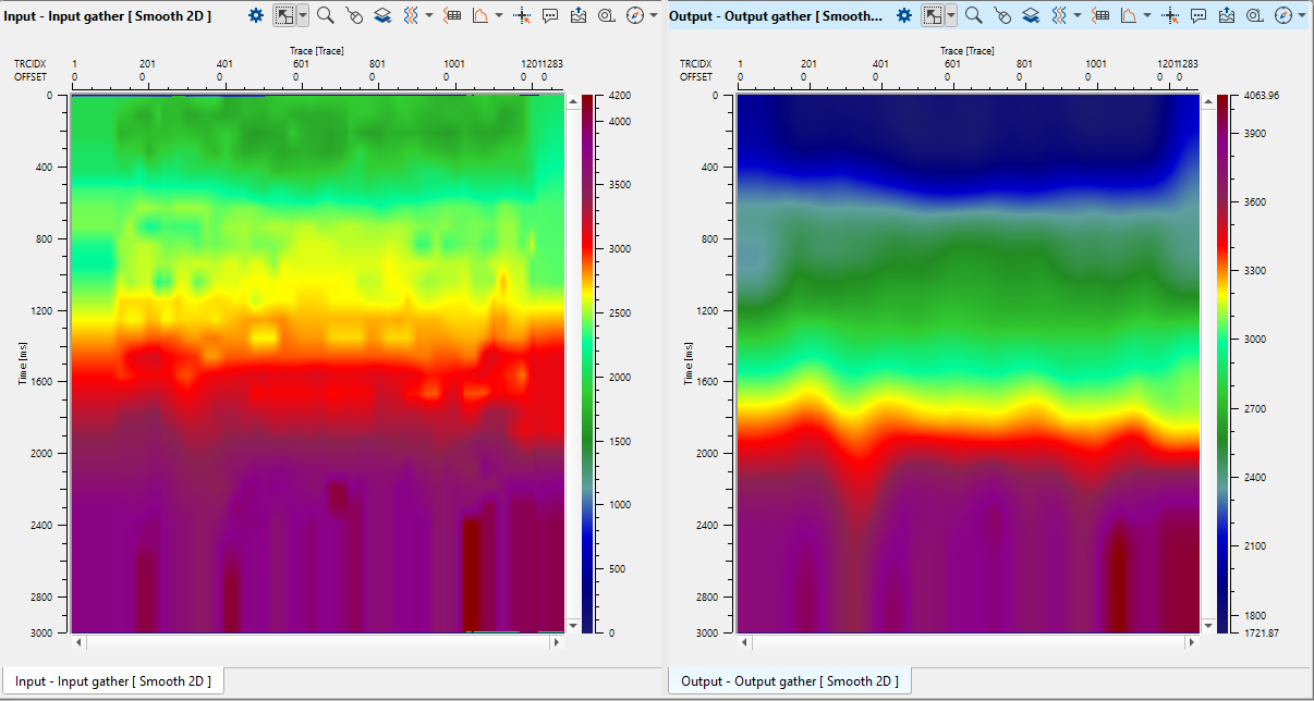
Execute Smooth 2D and open its vista views to check input and output velocity models:
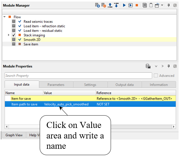
Add Save item module for saving velocity model into DB. Define input data and an output file name:
Input data:
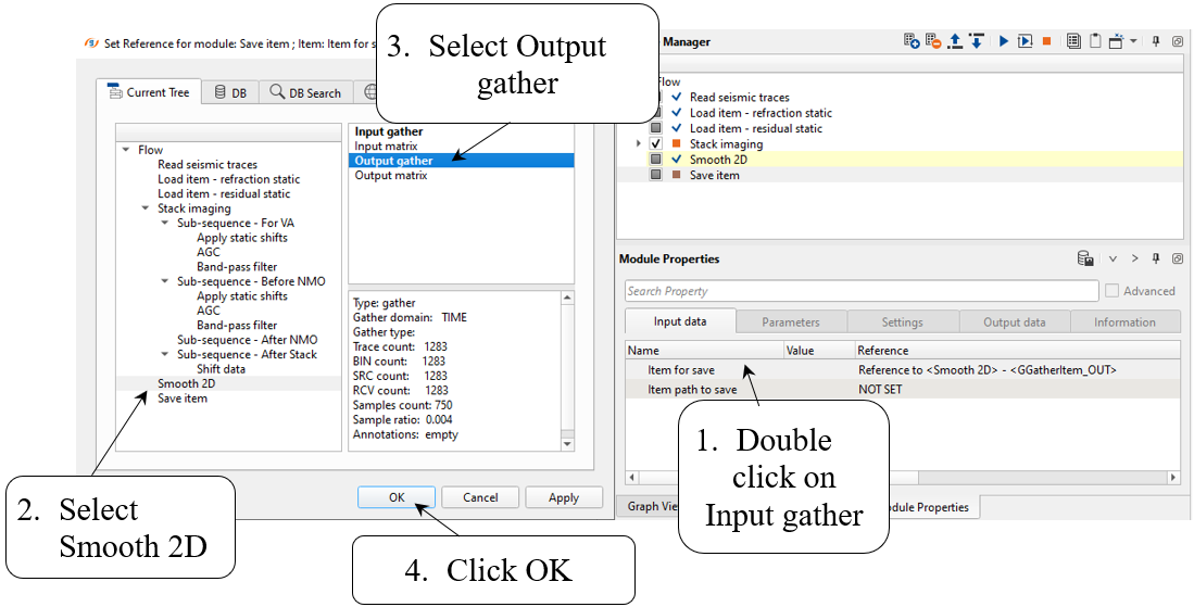
Write a name for output velocity library Velocity_auto_pick_smoothed and execute the module:
We finished auto-picking velocity and saved result on the disk. Now we can move on to the next chapter:
Next step >>> Noise attenuation after deconvolution (linear, random)
 If you have any questions, please send an e-mail to: support@geomage.com