 | NOISE ATTENUATION AFTER DECONVOLUTION |
|
<< Click to Display Table of Contents >> Navigation: Tutorials > Seismic Processing 2D LAND >
|
The second iteration of noise attenuation after deconvolution is one of the main part of signal processing sequence before migration step. Here we should apply more intensive parameters and algorithms for removing noise part from seismic data. We need to calculate and apply three of four interations of SCAC, because of the changes in amplitude distribution during the noise attenuation process. Therefore, we will repeat de-noise from the first iteration, but with more harsh noise attenuation parameters and add other algorithms as well.
----------------------------------------------------------------------------------------------------------------------------------------------------------
![]() There are many different modules for noise attenuation such a LNA, Adaptive ground roll attenuation and others, so you can try to use them and make some extra tests in this step.
There are many different modules for noise attenuation such a LNA, Adaptive ground roll attenuation and others, so you can try to use them and make some extra tests in this step.
-----------------------------------------------------------------------------------------------------------------------------------------------------------
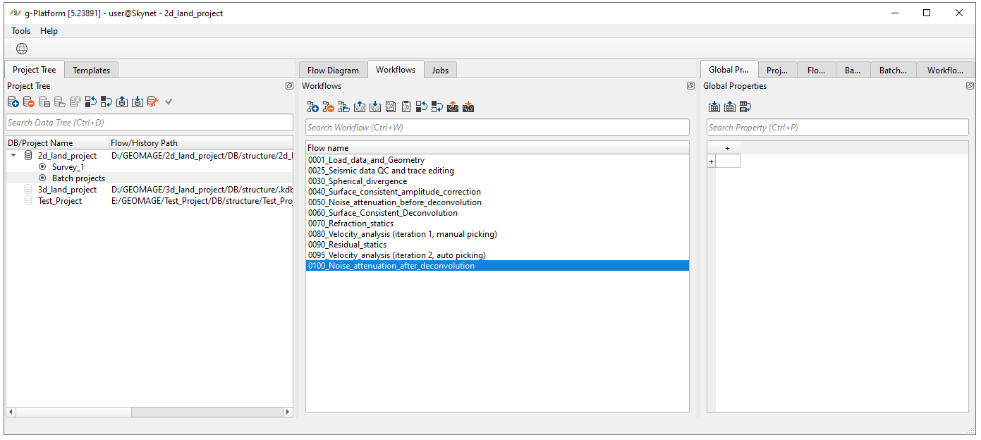
Create a new workflow 0100_Noise_attenuation_after_deconvolution:
The entire workflow look like that, let's go step by step:
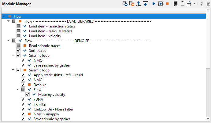
1. Load item - refraction statics - load refraction static
2. Load item - residual statics - load residual static
3. Load item - velocity - load stacking velocity
4. Read seismic traces - load traces after deconvolution step
5. Sort traces - sort traces by source for de-noise
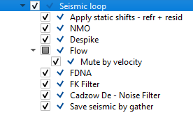
6. Seismic loop - process every sorted gather in a loop (one by one)
7. Apply static shifts - refr + resid - apply refraction and residual static corrections
8. NMO - apply normal move out correction
9. Despike - spikes attenuation
10. FDNA (+Flow - Mute by velocity) - high amplitude attenuation
11. FK Filter - linear noise(wave) attenuation
12. Cadzow De - Noise Filter - random noise attenuation
13. NMO - unapply - remove normal move out correction
14. Save seismic by gather - save seismic traces
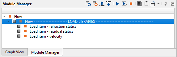
Add Flow module and rename it into Flow--- LOAD LIBRARIES ---- Flow. This module is used here just as a cosmetic feature, to separate load libraries part from the de-noise part.
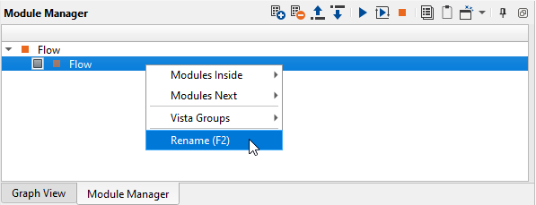
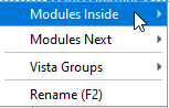
Put 3 Load item modules inside and rename them (add comments). Use Module Inside or drag'n'drop function:
Let's configure all Load items:
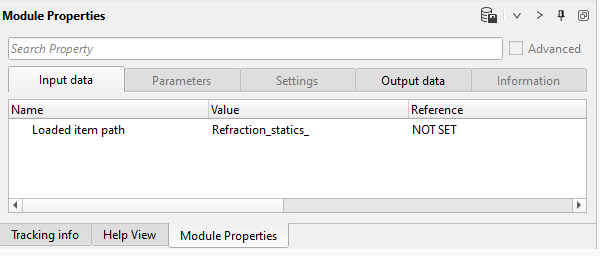
1) Load item - refraction statics. This module is used for loading refraction static library and apply it by Apply statics shifts later.
Choose the input static file Refraction_statics_ from DB:
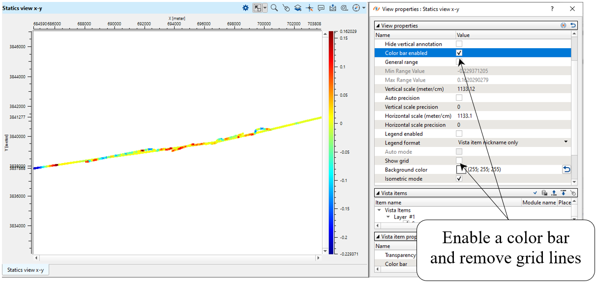
Execute the module and open vista view, check statics corrections:
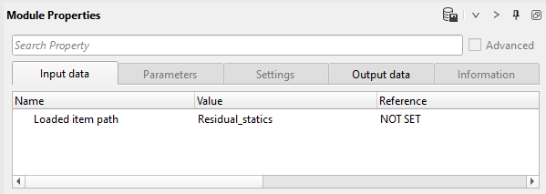
2) Load item - residual statics. Load residual static corrections (library) from DB and check it via vista view:
3) Load item - velocity. Load stacking velocity (library) from DB:
Add Flow --- DENOISE -------------- module, which is used also just as a cosmetic feature, to separate load libraries part from the de-noise part.
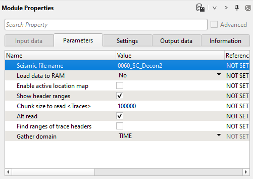
4) Read seismic traces. Define the input seismic file parameter 0060_SC_decon2:
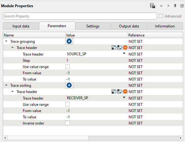
5) Sort traces. Sort traces by SOURCE_SP and RECEIVER_SP for de-noise process:
6) Seismic loop. Add all necessary modules inside:
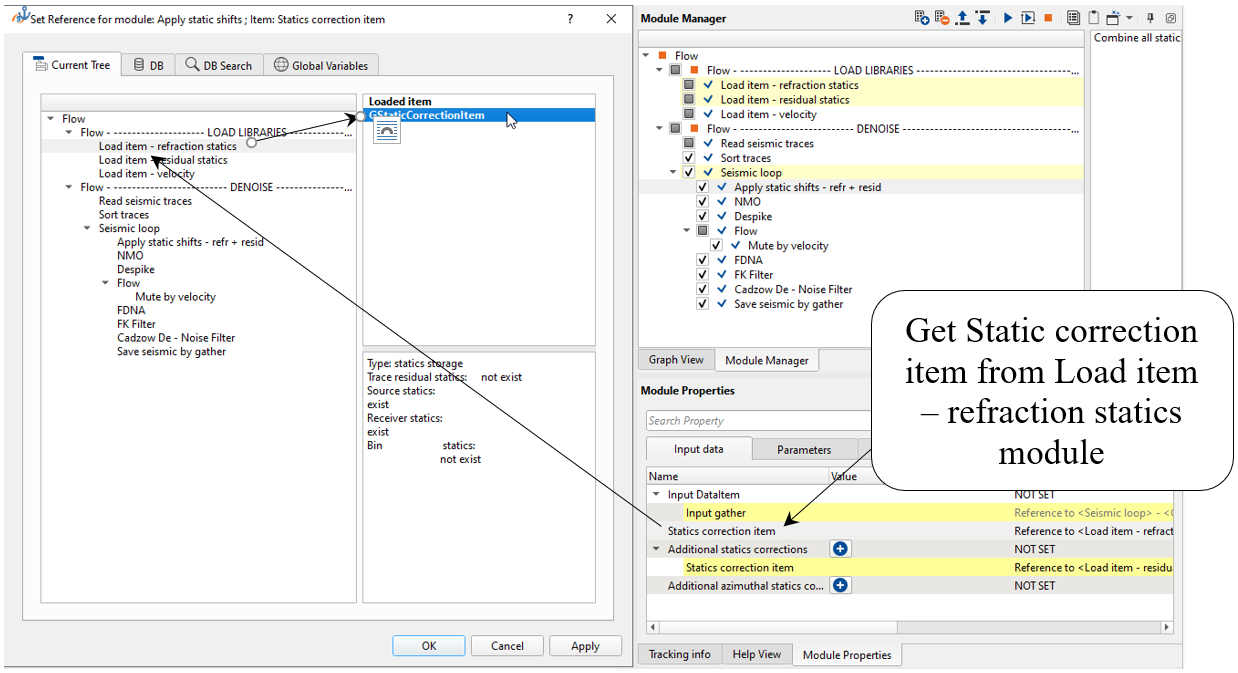
7) Apply static shifts - refr + resid. Here we are going to apply all static corrections that were calculated at previous steps: refraction and residual.
Define input parameters: Statics correction item we can get from Load item - refraction statics where we already have imported static library:
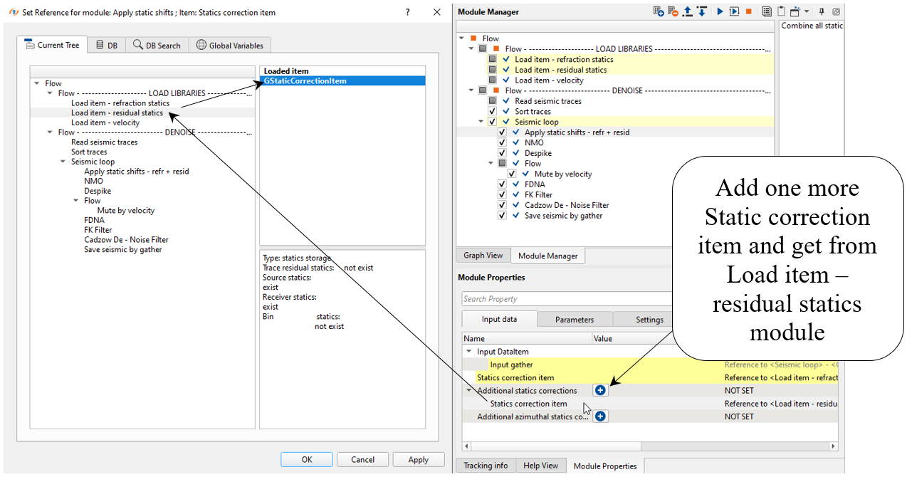
Add another static correction here, just click on ![]() plus button, then double click on Statics correction item and choose residual static library from Load item - residual statics:
plus button, then double click on Statics correction item and choose residual static library from Load item - residual statics:
--------------------------------------------------------------------------------------------------------------------------------------------------------------------------
![]() Notice that current processing is on the floating datum, and we will shift seismic data to the constant/final datum in further processing steps. Floating datum is written into BIN_ELEV header, so you can check it by using QC trace geometry module (header visualizing). This BIN_ELEV is used for static calculation by using Shift data module, Stack Imaging and other.
Notice that current processing is on the floating datum, and we will shift seismic data to the constant/final datum in further processing steps. Floating datum is written into BIN_ELEV header, so you can check it by using QC trace geometry module (header visualizing). This BIN_ELEV is used for static calculation by using Shift data module, Stack Imaging and other.
--------------------------------------------------------------------------------------------------------------------------------------------------------------------------
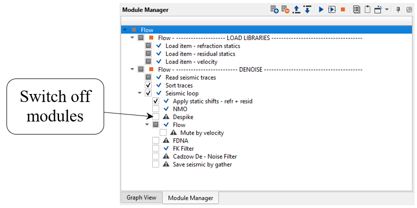
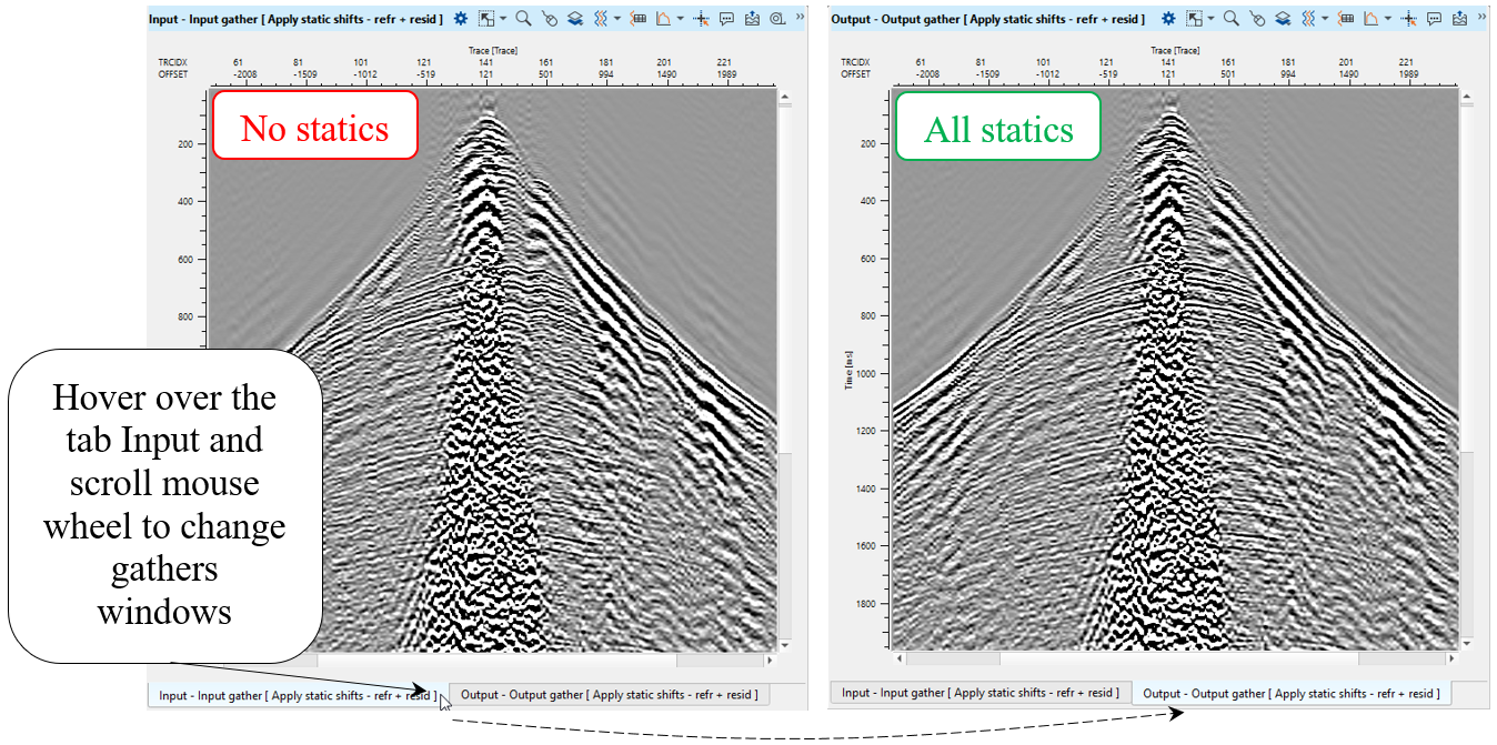
Execute all modules that we already have prepared before (load items, read seismic traces, sort traces, seismic loop) and check static applying via gather vista view - before and after static corrections. Open vista groups from Apply static shifts - refr + resid and flip gathers with using a mouse wheel. Pay attention that you can switch-off modules in the workflow for skipping them:
Zoom a gather, please don't forget about sync button ![]() . It makes synchronization between all gathers (vista windows).
. It makes synchronization between all gathers (vista windows).
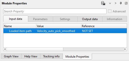
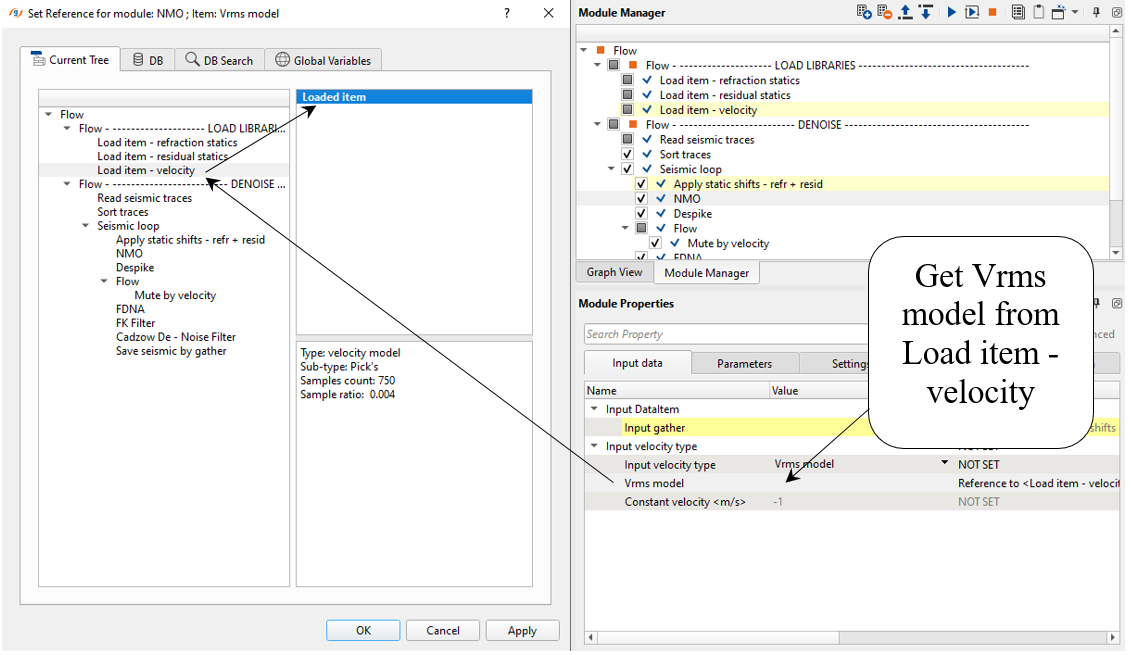
8) NMO - apply normal move out correction by using stacking velocity. Define an input data parameters: get Vrms model from Load item - velocity:
--------------------------------------------------------------------------------------------------------------------------------------------------------------------------
![]() IMPORTANT! We must apply NMO corrections on gather which was sorted by CDP. But in this case of denoise task by source gathers we can apply NMO and remove it after denoise.
IMPORTANT! We must apply NMO corrections on gather which was sorted by CDP. But in this case of denoise task by source gathers we can apply NMO and remove it after denoise.
--------------------------------------------------------------------------------------------------------------------------------------------------------------------------
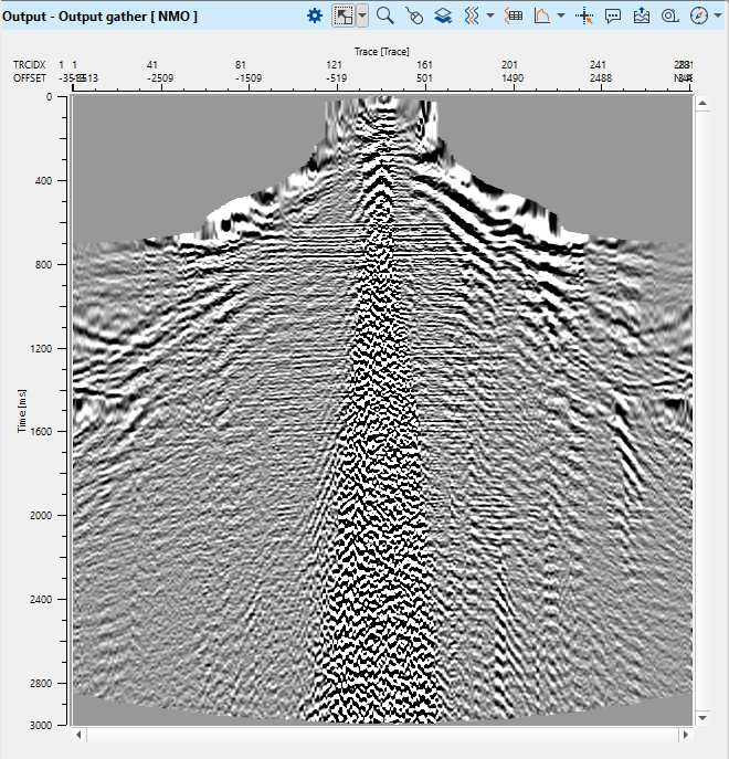
Execute NMO, open vista view window Output gather [ NMO ]:
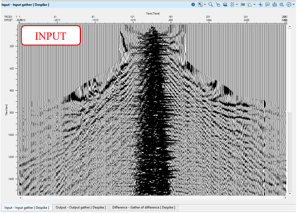
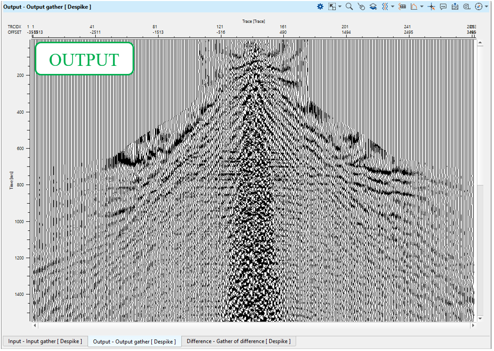
9) Despike module allows to remove amplitude spikes (high amplitude values which are larger than adjacent values) from seismic traces. Spikes are not normal seismic signal, they are usually created by the recording equipment and hence should be removed. Spike identification and removal is based on the average (depending on the chosen parameter) amplitude calculated in a time window and spatial window for each sample of the seismic trace in accordance with the chosen threshold coefficient.
Define all the parameters, you already familiar with this module, for now we need to set parameters for more intensive noise attenuation:
Parameters:
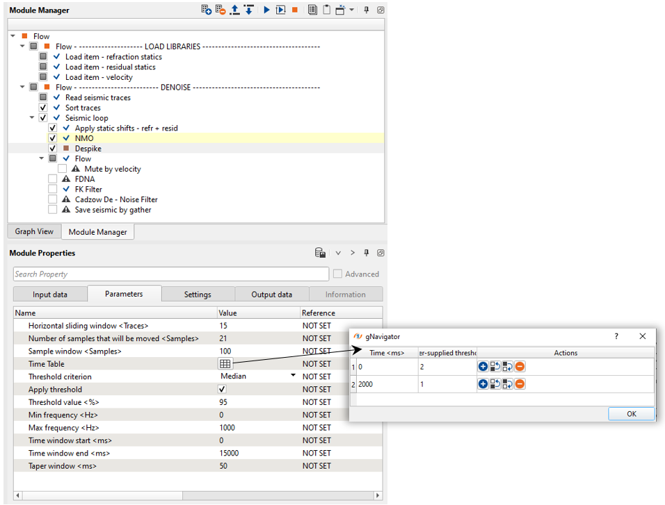
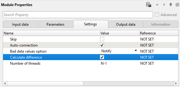
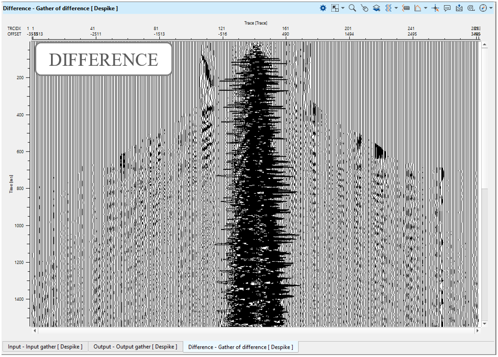
Don't forget to switch on a Calculate difference parameter for testing and switch off it when you launch a job for the entire data set:
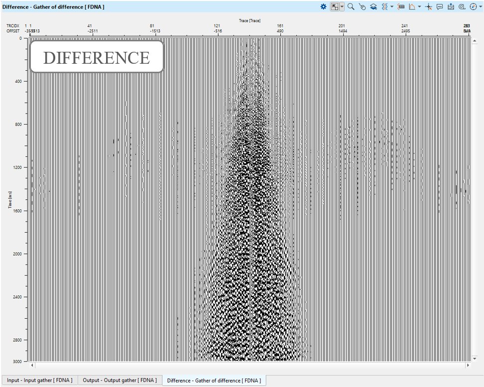
Execute the module, open vista windows and check the result (input - output - difference):
10. FDNA (+Flow - Mute by velocity)
First, we need to create a model for FDNA.
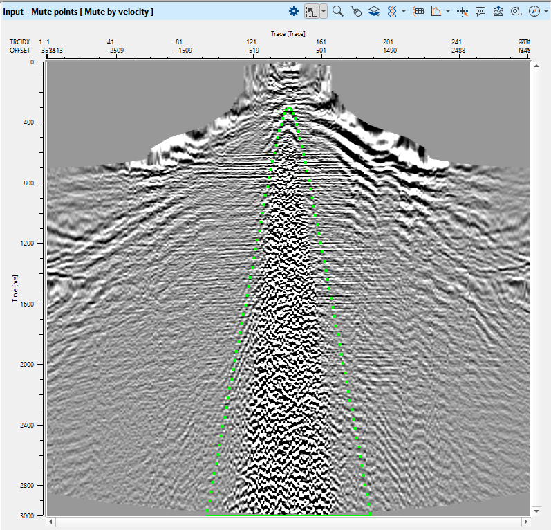
FDNA requires a model that includes only signal part of the seismic data. Put Mute by velocity inside the flow. We need it for creating a model for FDNA module. Open vista item and create a mute function for removing a noise area in ground roll place on a gather. This step we already discussed in the previous chapter Noise attenuation before deconvolution (linear, spikes, ground-roll):
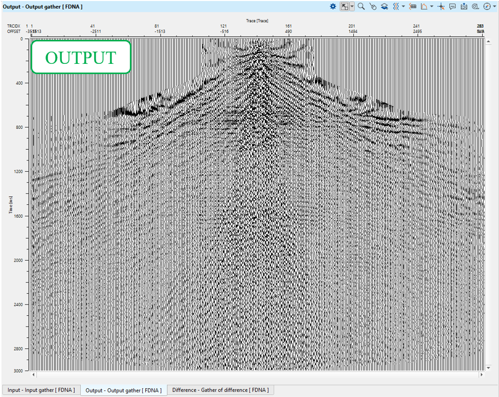
Second, apply noise attenuation via FDNA module:
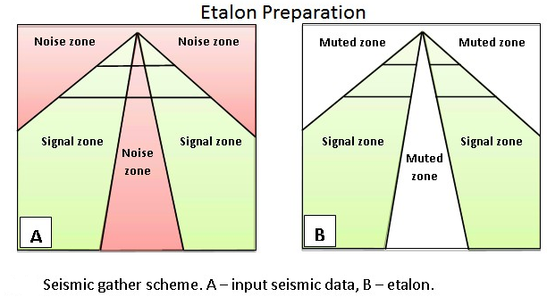
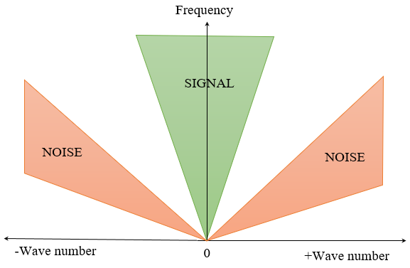
FDNA (Frequency Dependent Noise Attenuation) module uses frequency-dependent and time-variant algorithm where an amplitude threshold values are defined in a trace neighbor area (T-X) for detecting and noise attenuation according to different frequencies and different time windows. The attenuation process consists of two steps – First prepare the etalon (model) and noise attenuation data sets. The etalon should contain only the signal zones, with the noise zone muted (see Pic.1). The module estimates the median value of the amplitude spectrum in the sliding windows of the etalon data set, and for each window computes an operator using the threshold value. The procedure attenuates amplitudes whose values exceed the specified threshold.
Parameters:
Input data – Two seismic data sets are input to the FDNA module.
The Input gather are 2D/3D seismic gathers in source or receiver sort order. It is better if they are NMO corrected and static corrections have been applied, but for this step we can apply denoise sequence in a soft mode without NMO correction.
The Model gather is the etalon of 2D/3D seismic gathers in source or receiver sort order. The same idea: it is better if they are NMO corrected and static corrections have been applied, but for this step we can apply denoise sequence in a soft mode without NMO correction.
Seismic loop makes automatic connections between all modules in a sequence under that seismic loop and the user cannot disconnect them. In this case, we need to use an additional Flow module inside of the Seismic loop for etalon preparation. Put the mute modules into a Flow inserted into the Seismic loop and then connect the output muted data to the Model gather field of the Input data tab of the FDNA module. The Input gather on the Input data tab will be automatically connected to the previous module in the Seismic loop processing flow.
Firstly, we need to create an etalon for FDNA by using Mute by velocity module:
Number of traces to use for the sliding window. This window is used for local attenuation.
Default: -1 (all traces)
Range: from 1 to max traces in the input gather
Time in milliseconds for sliding window. This window used for local attenuation. The taper zone between sliding windows is ¼ of time window length default 200ms.
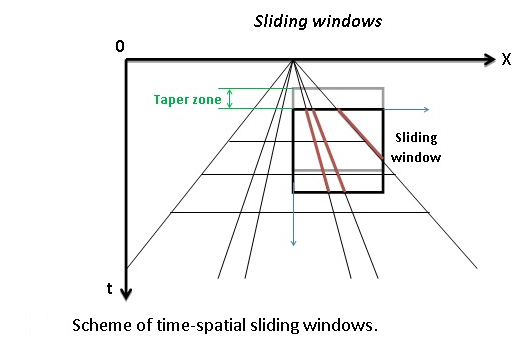
Sliding time window - Amount to advance the sliding time window each shift
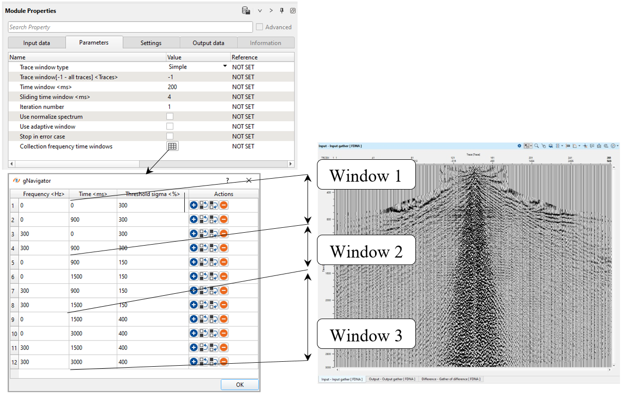
Three parameters of basic control noise attenuation:
• Frequency– frequency for attenuation;
• Time– time value for threshold;
• Threshold– the limiting parameter for calculating threshold values to attenuate excessive amplitudes.
Carefully prepare the etalon (model) data, try to mute the high amplitude zones and include the signal zones.
Control the noise attenuation by using the threshold parameters and the ability to specify the thresholds in a time variant manner and by frequency.
This procedure is more effective in the first steps of the seismic data processing flow when noise zones still have high amplitudes. The input seismic data should not be amplitude normalized.
Define all the parameters, we need to set parameters for more intensive noise attenuation:
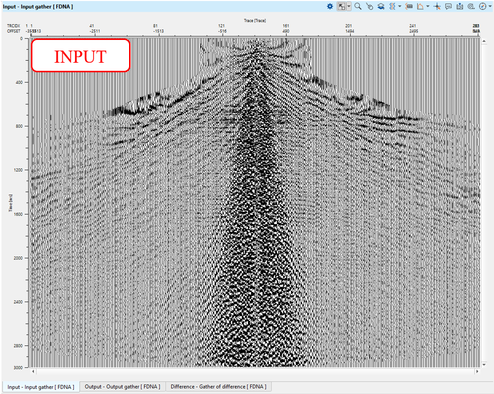
Execute the module and check the results:
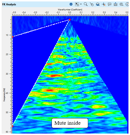
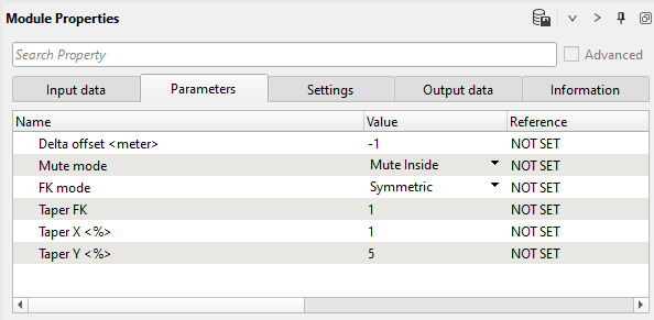
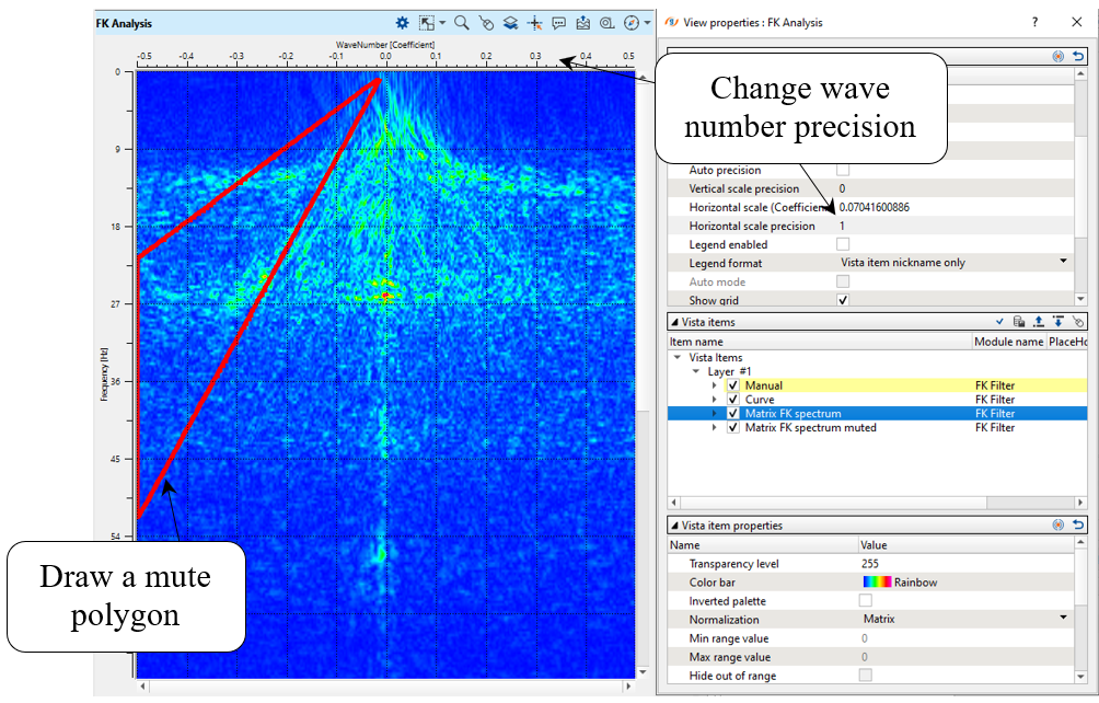
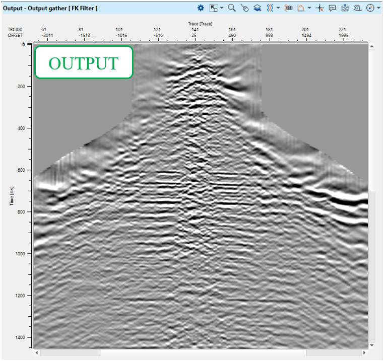
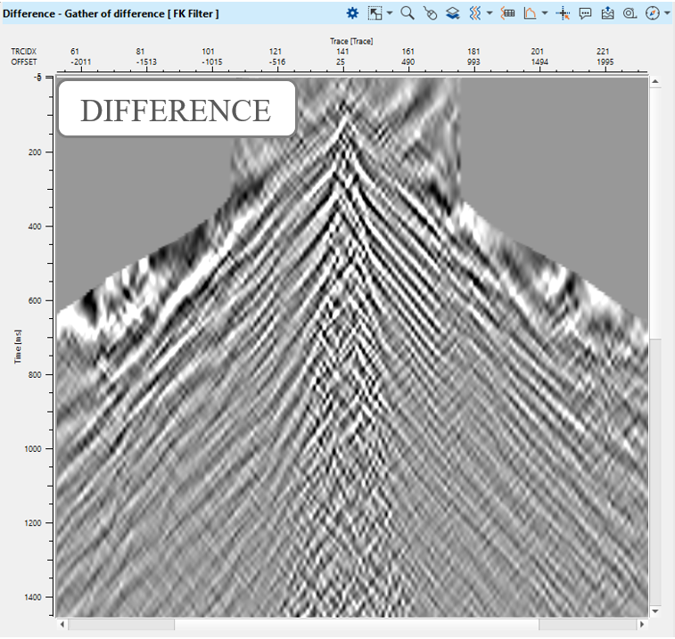
11) FK Filter. This filter module works in FK domain, which represents two dimensional Fourier transform (FT) over time and space, where F is frequency (FT time) and K is wave number (FT space). The algorithm removes energy from seismic data by applying user-defined polygon in frequency-wave number domain. You can also use another module for this task called LNA (Linear Noise Attenuation), because it has min and max velocity parameters for filter definition instead of polygon.
Parameters:
Delta offset <meter>
| Distance between traces (meters) in the input gather, need to calculate FK spectrum. By default it is -1, it means read offsets from traces headers and calculate delta offset automatically. |
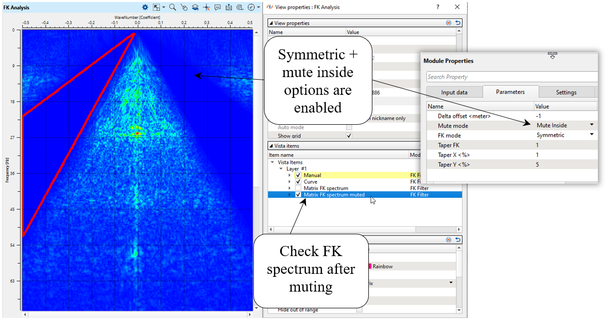
| Mute mode: |
| Mute inside - remove data inside the user-defined polygon: |
FK spectrum with mute inside parameter.
| Mute Outside - remove data outside the user-defined polygon: |
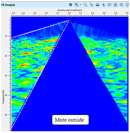
FK spectrum with mute outside parameter.
| FK mode: |
| Asymmetric - remove only one inside of the FK spectrum in accordance with the polygon: |
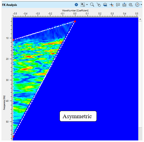
FK spectrum with asymmetric parameter.
| Symmetric - remove both sides (-/+ K) of the FK spectrum in accordance with the polygon: |
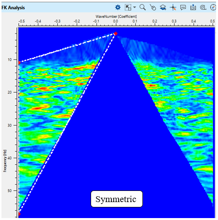
FK spectrum with symmetric parameter.
| Taper FK |
| Tapering zone for polygon in FK domain in order to avoid edge-effects. |
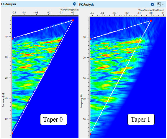
FK spectrum with different taper parameters.
| Taper X <%> |
| Tapering zone along the X axis (wavenumber) in FK domain in order to avoid edge-effects. |
| Taper Y <%> |
| Tapering zone along the Y axis (frequency)Y in FK domain in order to avoid edge-effects. |
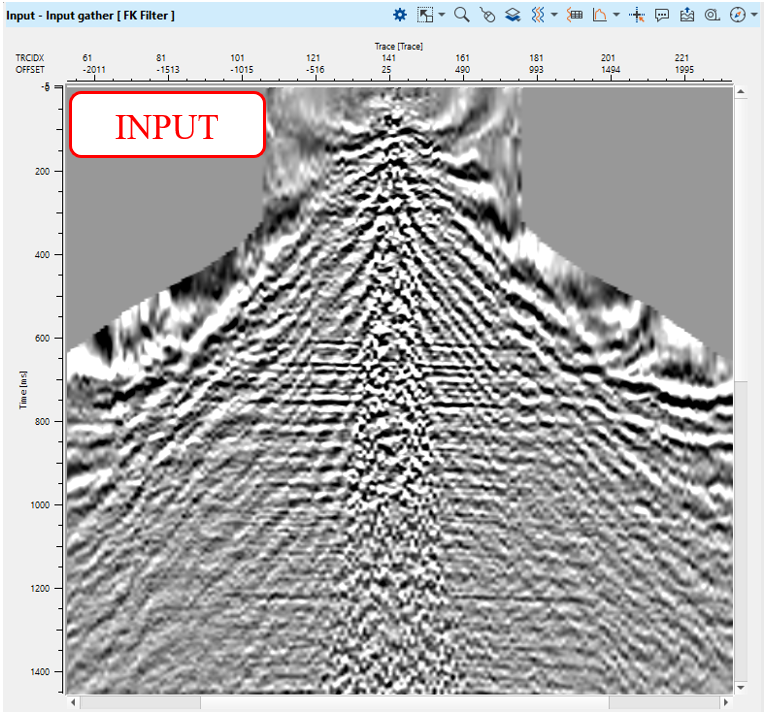
Define module's parameters and execute it:
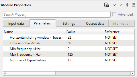
12) Cadzow De - Noise Filter is based on rank reduction of matrix on frequency slices to attenuate the random noise. This can be done in pre and/or post stack data. Even though the parameters are similar to RNA (Random Noise Attenuation) module, the working principle is slight different as far as the eigen values are concerned. In this case, these eigen vectors are applied on multiple dimensions (3 or more). The other advantage of Cadzow De-Noise Filter is that it can work on flat or dipping events. It preserves the dips of steeply dipping events while attenuating the random noise.
Parameters:
Horizontal sliding window <Traces>
Number of traces for creating spatial sliding window.
Time window <ms>
Time interval in milliseconds for creating spatial sliding window. Usually starts from 50 ms, there may be artifacts on the output image in case of too small window
Min frequency <Hz>
Start frequency for processing.
Max frequency <Hz>
End frequency for processing.
Number of Eigen Values
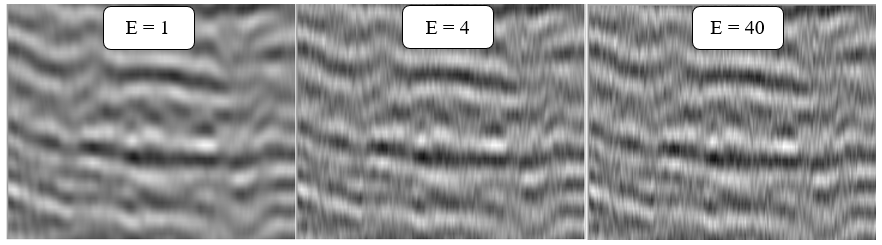
Number of eigenvalues, actually it is representation of the matrix of samples for each frequency section - high value, harsh denoise effect. In other words, it is number of dips in the superposition. Pay attention on geological structures (dips), the main task is to find a balance between denoise and structure preserving (or signal event in case of prestack data).
,
ʎ - eigen value, v - eigen vector
Seismic image with different eigen values - 1, 4 ,40.
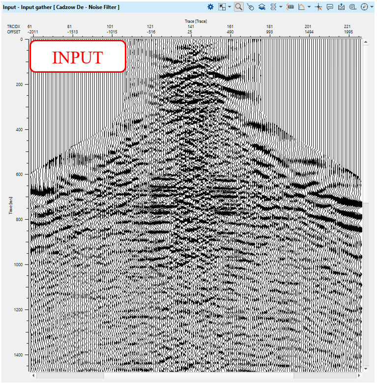
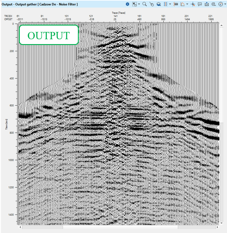
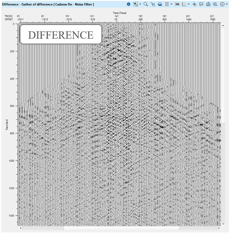
Define module's parameters and execute it:
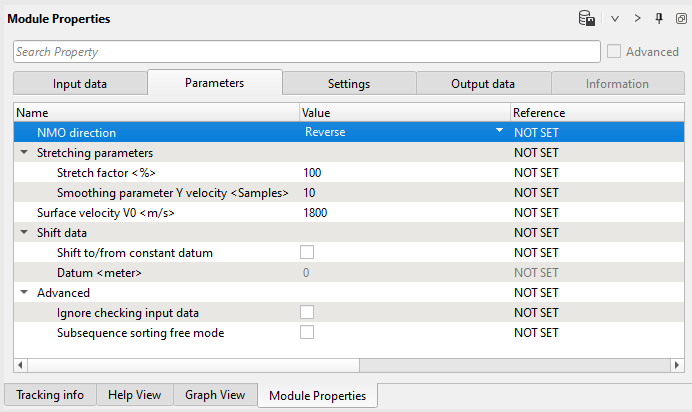
13) NMO - unapply - remove normal move out correction by using stacking velocity. Define an input data parameters: get the sameVrms model from Load item - velocity and choose Reverse option in parameters:
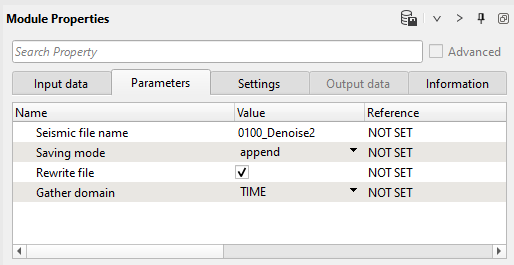
14) Save seismic by gather. Define an output name 0100_Denoise2. Turn off all difference calculations and execute processing for the entire:
Final extra step is quality control:
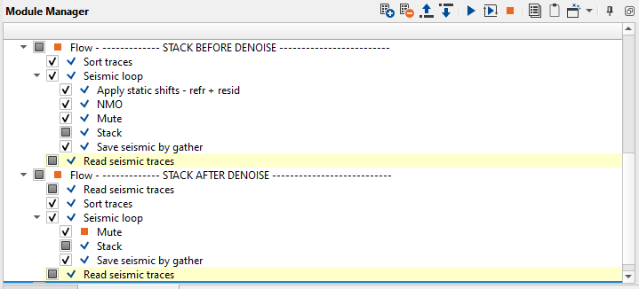
Create stacks before and after de-noise. Try to build a workflow based on the following structure:
Please, pay attention that stacks are on float datum! It is better to move it to the final datum by using Shift data module. Add this module (or use datum paramtere in Stack Imaging) and move seismic data to the constant datum.
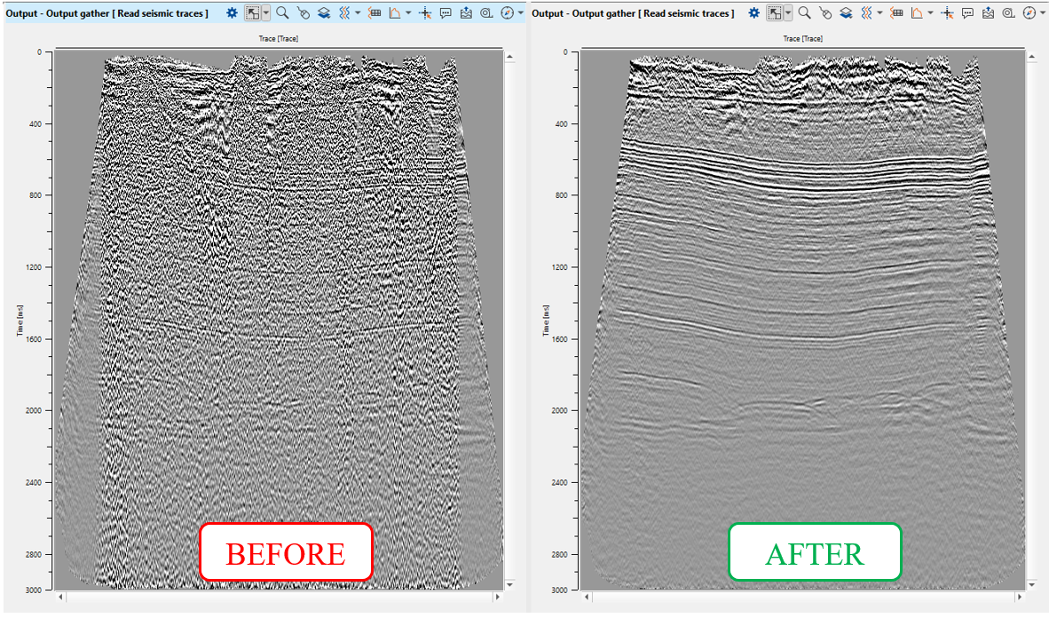
Calculate difference via Expression calculator and if de-noise is too harsh, make de-noise softer.
Next step >>> Multiple attenuation (iteration 1).
 If you have any questions, please send an e-mail to: support@geomage.com
![]() Frequency Dependent noise attenuation (FDNA) - Geomage g-Platform - YouTube
Frequency Dependent noise attenuation (FDNA) - Geomage g-Platform - YouTube
![]() Linear Noise attenuation (LNA) - Geomage g-Platform - YouTube
Linear Noise attenuation (LNA) - Geomage g-Platform - YouTube
![]() Despike - Geomage g-Platform - YouTube
Despike - Geomage g-Platform - YouTube