Geomage MultiFocusing technology allows finding optimal values of radius of curvature R (see figure below) and emergent angle Beta (depending on the reflector's dip) for the central point X0 at each sample ![]() of the section or cube.
of the section or cube.
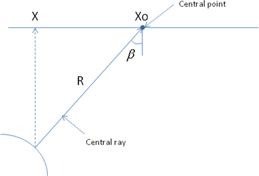
Values R is recalculated to dip-free RMS velocity by the formula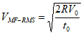
where ![]() is the shallow subsurface velocity.
is the shallow subsurface velocity.
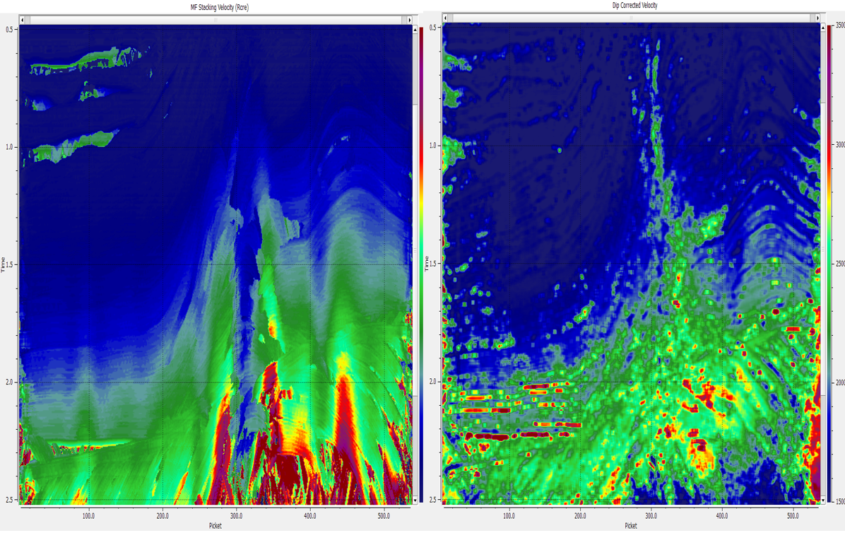
The procedure of dip-correction is a transition of ![]() to the accurate position (laterally and vertically) connected with vertical ray. For this purpose, velocity displaced from the stack domain to the migration domain for subsequent migration.
to the accurate position (laterally and vertically) connected with vertical ray. For this purpose, velocity displaced from the stack domain to the migration domain for subsequent migration.
In other words becoming dip-corrected ( vertical ![]() ).
).
The interpolation and smoothing of ![]() field is performed within the section or cube according to migration practice.
field is performed within the section or cube according to migration practice.
The above method has two implementations - for ZOMF and COMF technology:
Map migration
The module of map migration is a spatial transition (migration) of the velocity field to the accurate position that is connected with the normal ray. For this purpose, the velocity is displaced from the stack domain to the migration domain for subsequent migration. This performed according to optimal values of radius of curvature RCRE and emergency angle Beta for the imaging point at each time sample.
Inputdata – ZO-MF database data handle
Outputdata – Map migrated velocity filled/unfilled
Visual – VMF-RMS, Map migrated velocity, Map migrated velocity filled, semblance
2D CO map migration
The procedure of map migration is a spatial transition(migration) of the velocity field to the accurate position that is connected with the normal ray. For this purpose, the velocity is displaced from the stack domain to the migration domain for subsequent migration. This performed according to optimal values of radius of curvature RCRE and emergency angle Beta for the imaging point at each time sample. Unlike ZOMF(map migration), COMF map migration calculated for each offset class and final velocity is the sum of all velocities of offset classes.
Inputdata – CO-MF database data handle.
Outputdata – Map migrated velocity filled/unfilled.
Visual – VMF-RMS, Map migrated velocity, Map migrated velocity filled, semblance