Once the user reads the seismic, navigation and/or spread information, it is time to assign the geometry. In g-Platform we use "Geometry application" module to assign the geometry. It is the same module for the land/marine.
Module name "Geometry application"
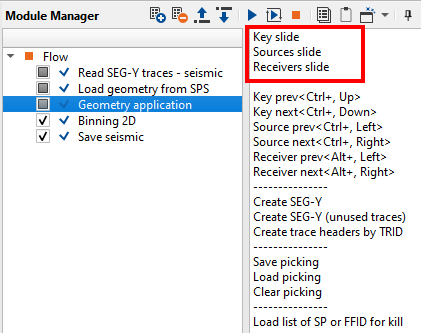
To start with, the user should add the module "Geometry application" to the existing flow as shown below.
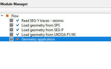
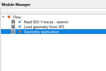
If you observe, in the above image, we can see different modules to read the navigation/spread information. It is advised to the user that add/select the appropriate module as per your requirement to read the navigation and/or spread information from the above image. On the right hand side we have chosen "Load geometry from SPS" module for this exercise.
For the Geometry application module, we need to provide the input(s) i.e. seismic and navigation information. Now go to the Input data of Geometry application module and make the references/connections as shown below.
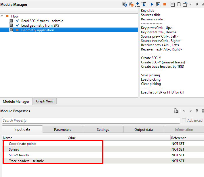
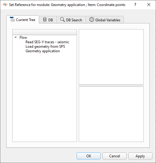
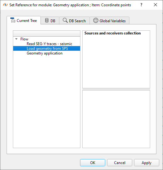
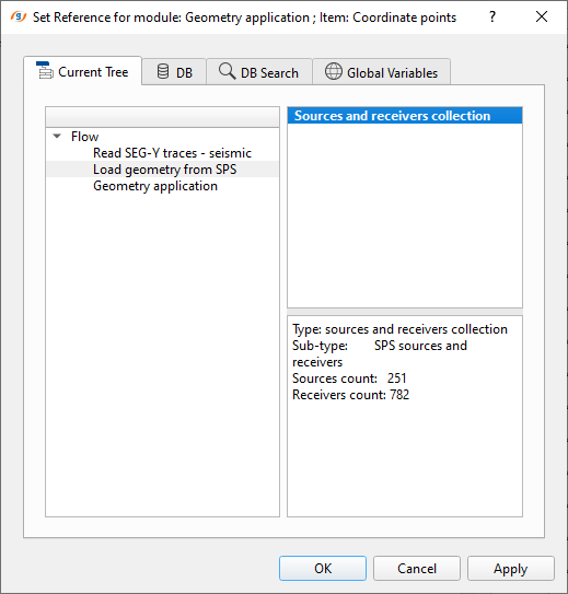
We need to make references/connections to the Input data. For Coordinate points, we double click on the coordinate points and it will pop up a new window as shown below. Select "Load geometry from SPS" module followed by "Sources and receivers collection" and click OK.
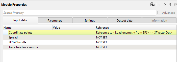
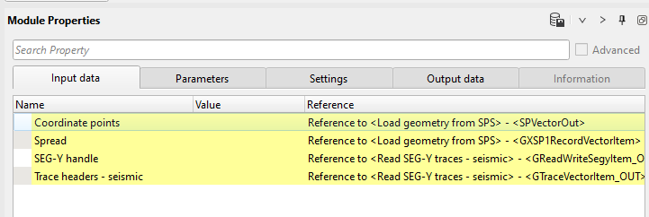
If we observe, the coordinates points in the input data tab background color turned into yellow. Further we can see the "Reference" tab says that "Reference to <Load geometry from SPS>. Similarly we can connect/reference the other items like Spread, SEG-Y handle and Trace headers - seismic as shown below.
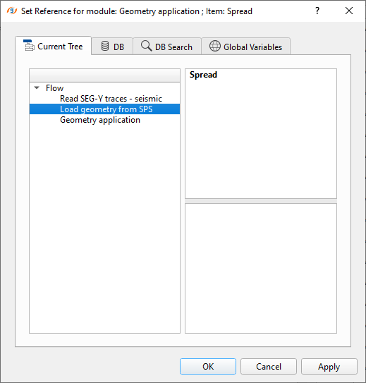
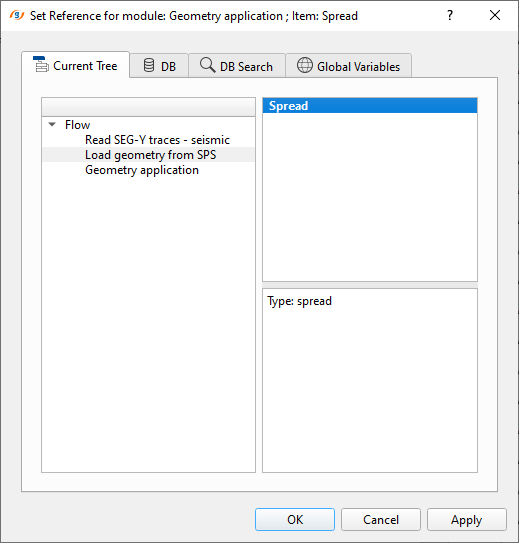
To reference Spread, we've chosen Load geometry from SPS module again and select the spread option. Remember, we need to double click on Spread (it is the norm in g-Platform to connect/reference the user should double click on that particular item (for all the modules however there may be some exceptions)).
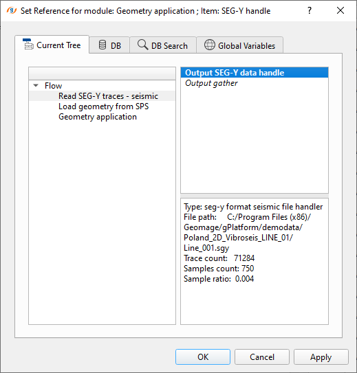
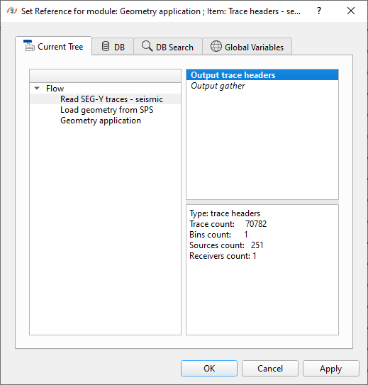
Now comes the SEG-Y part. It is similar to the Load geometry from SPS module however this time we choose "Read SEG-Y traces" module for "SEG-Y handle" and "Output trace headers" for "Trace headers - seismic" and click OK.
Now if we look at the input data tab of Geometry application, it should like look this
Until now, we connected/referenced our seismic and navigation data to the Geometry application module. Now comes the Parameters tab. Here the user defines the parameters (there aren't many to define but few of them are worth to mention here).
Velocity Define the velocity line to check whether the assigned geometry is correct or not.
Recreate channel numbers In case the channels are not in order or need to be renumbered. The user can check this option otherwise just ignore it.
Create live only traces By default it is checked ON. It will only pass on live channels.
Data key By default it is FFID which is referenced to seismic data.
Spread key By default it is also FFID which is referenced to navigation data. These are the reference keys to match the seismic with navigation data and assign the geometry.
Spread from trace headers In case the spread information is already in the SEG-Y trace headers then the user can check this option.
Interpolate SP 2D points If the SP numbering is not incremental by 1 or something in the navigation data then it will interpolate the SP numbers.
Perpendicular inline shifts This is very useful option when there is a moving source and/or receiver.
AUX TRIDS Provide the auxiliary traces if there are any. To input the auxiliary traces, the user should click on the ![]() icon.
icon.
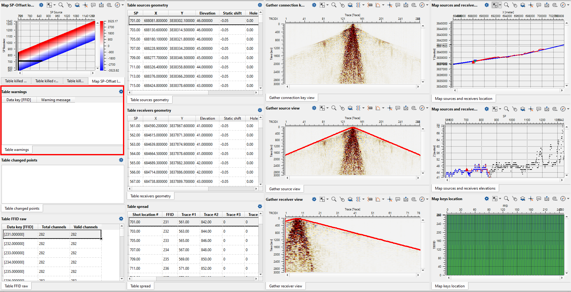
After assigning the geometry, the user should QC thoroughly to check everything is correct before proceeding further. As we mentioned earlier, g-Platform offers many QC tools to visualize and check the accuracy of the geometry. It generates many vista items. If there are any issues with the geometry the user should look into the "Table warnings" and act accordingly.
In order to quickly go through the entire line to look for any geometry issues etc, the user can click on the Sources slide button on the action items menu. It will move to each shot with a delay of 1000ms (by default. This can be changed at Sliding parameters).
If the user wants to save the geometry assigned (binning information won't be there yet) gathers then they can use the option "Create SEG-Y" to directly output/write SEGY file without building a new workflow. Cool isn't it?
How to kill traces/mark them as dead traces/polarity reversal:
In order to do any one of them, the user should go to the Gather source view window and click on control item ![]() icon. This will comes up with many options as shown below.
icon. This will comes up with many options as shown below.
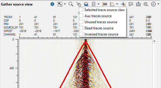
1. Go to Control item ![]() of the Gather source view window and select one option at a time.
of the Gather source view window and select one option at a time.
2. Prior to mark the traces, go to Select traces icon ![]() and click on it to activate the option
and click on it to activate the option ![]()
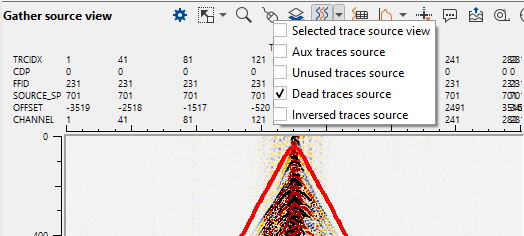
3. Now select the traces to mark them as Dead traces since our option is "Dead traces source". To visualize the changes, please annotate the trace headers with TRACE_TYPE so that we can see the changes in the TRACE_TYPE as shown below.
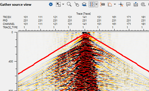
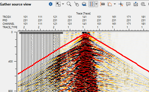
If we look at the above images, on the left hand side we see the TRACE_TYPE as 1 whereas on the right hand side we observe the TRACE_TYPE as 2 which is changed after selecting the traces as "Dead traces source". To make any changes, the should hold MB3/RMB and drag it.
g-Platform processing suite stores this information in it's trace headers and updates them.
How to correct the position of the shot/receiver?
In case the positioning of the shot/receiver record is wrong due to navigation or for some other reason, we can easily fix this issue. In this exercise, we are changing the already corrected geometry location to a wrong location and bring it back to it's original position. To do that,
1. Go to Map sources and receivers location map select the Control item icon ![]() . This gives us the options as shown below.
. This gives us the options as shown below.
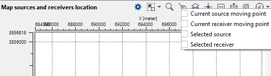
2. Select Current source moving point/receiver moving point. In this case, we are selecting Current source moving point as shown below.
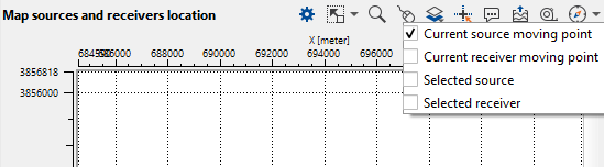
3. Now on the Map sources and receivers location, hold MB1/LMB and drag the current source point to any where on the location map.
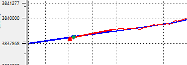
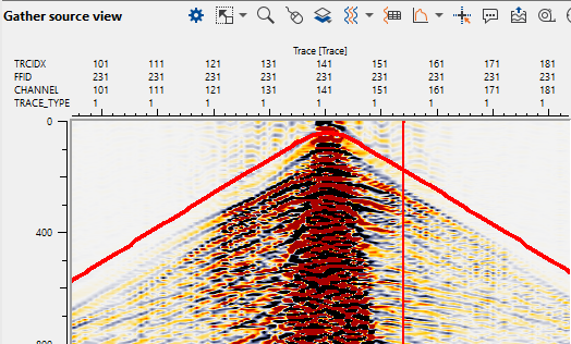
We are showing current shot location on the location map (Red Triangle) and the corresponding assigned geometry to that particular shot. (This is the correct geometry shot)
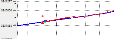
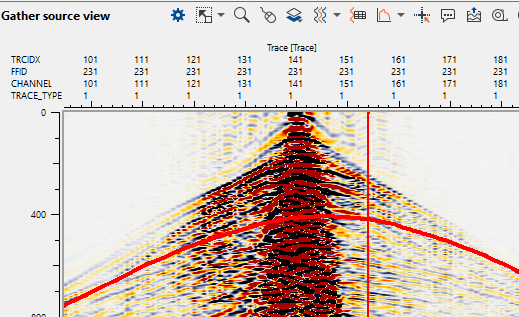
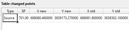
In the following image, we moved the shot location to a different X,Y coordinates (red dot). Now look at the shot geometry. Plotted velocity line is changed due to incorrect geometry assignment. The moved shot location or new shot location coordinate points are available in "Table changed points".
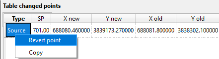
4. To correct the geometry, we should go to the Table changed points and do MB3/RMB select "Revert point" option to bring it back to it's original position.
5. Now look at the Map sources and receiver location and the corresponding Gather source view. They should be the same as shown on point 3.