Module name : Parameterization - MF Engine
Main function for MF Search engines that determines all parameters of MultiFocusing operator.
This module prepares MF parametrization tables that used by MF Engine procedures. The module determines all parameters for existing types of implemented MultiFocusing engines
Output data – MF Tables Parametrization
Input data:
SEG-Y data handle (for auto Time Range)
Service object provides the ability to read seismic data in specified format. It used for automatic determination of time range in seismic data (optional)
Trace headers (for auto Aperture Offsets)
Table of trace headers. Is used for automatic determination of minimum and maximum offsets (optional)
Major parameters list
V0
Used for calculation of time correction in MF and transformation R CRE<->V RMS-MF.
Usually is set equal to the Replacement Velocity.
Default: 1500
Use Prestack Mute function
Determination of type and form of MF Mute Function. There are 3 types of MF Mute functions; two of them based on the correlation between the time-offset and R CRE. For the shallow part of the data, the radius of the wave-front approximation cannot be much greater than the offset. For each time determines max offset for stacking using following equation:
OffsetMAX(t)=R CRE(t)*Mute Factor(t);
The difference between the types is in R CREdetermination.
•Firsttype– maximum offset determinates for each iterated CRE,
•Second type – the R CREvalues calculate from the low (left) border of the velocity constrain function for given imaging point location.
•Third type of MF Mute function is based on the limitation of maximum time correction during MF stacking.
Turn ON/OFF in order to switch to the second type MF Mute Functioncalculation, based on the velocity constrain
R-cre Range
Reference CRE Offset
Reference offset for CRE table calculation.
Default:3500
Range:usually around max offset of the seismic data
Time Step
Used for CRE radius table construction
Default: 8
R-cee Range
Parameterization for digitization of CEE radii search table. Table of radii is created as following; the difference between kinematic corrections for two neighbor radii on reference offset shouldn’t exceed the time step.
Reference offset corresponds to the stacking aperture (base of super-gather).
CEE Aperture
Reference offset for CRE table calculation
Default: 300
Range: usually corresponds to the stacking aperture
Anisotropy
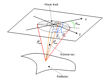
Anisotropy of the wave-front elements in MF is defined by three parameters R 1 CRE, R 2 CREand ɸ CREwith assumption that reflectors above the target reflector have low curvatures and anisotropy is limited. Parameters R 1 CRE, R 2 CRE, which can be recalculated into V RMSand V INT, are not dependant on dip unlike in CMP where Vst depends on dip.
Azimuthal variation of MF moveout velocity is an ellipse in the horizontal plane, irrespective of the type or degree of intrinsic anisotropy. Parameters R 1 CREand R 2 CREare transformed into V 1 RMS==V FASTand V 2 RMS==V SLOW. These additional parameters make possible to take into the account the anisotropy of the subsurface. In the same time this dramatically increase the calculation time
Turn on/off the anisotropy search.
•NON – no anisotropy.
•One Azimuth In Line Direction – Anisotropy search performed only along 1 azimuth.
•All Azimuths – search performed for all azimuths.
Default:NON
Max CRE Anisotropy
Maximum difference between VFAST and VSLOW to be searched, directly influence on calculation time
Default:0.2
Values:0,6-0.9
Aperture
Parametrization of super-gather formation. Super-gather is actually a time projection of the first Fresnel Zone. All events within this range will be stacked into one sum trace.
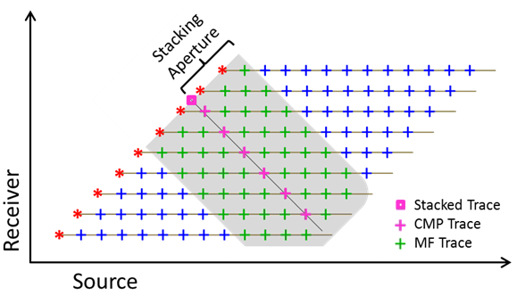
The size of multifocusing (MF) aperture (superbase) dynamically adjusted during simultaneous scan of wavefront parameters while the dominant frequency of seismic data predefined within the project scope. The formula used for aperture estimation is:
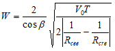 ;
;
Where:![]() – angle of wave incidence to the central point of superbase,
– angle of wave incidence to the central point of superbase, ![]() – velocity in the upper subsurface,
– velocity in the upper subsurface,
•T – period of the signal (T=1/f, f- frequency); ![]() – radius of curvature of the wavefront which is connected with Vrms with the formula
– radius of curvature of the wavefront which is connected with Vrms with the formula![]() – radius of curvature of the reflector.
– radius of curvature of the reflector.
The aperture W is corresponding to 100% of the first Fresnel Zone projection.
For example, when Fresnel zone projection taken as 50% in specific project, that means that application will estimate suberbase for each triplet of wavefront parameters for each sample and will take a half of that value.
Aperture in Inline Direction / Aperture in Xline Direction
Aperture in stack line direction. For 2D case an only aperture in Inline direction used. Measured in in the percentages of the First Fresnel Zone.
Default: 50
Range: 10-100
Average Frequency
Frequency used to compute size of the First Fresnel Zone.
Default:45
Range:Usually used nominal frequency of the seismic data
Correlation parameters
Min Fold
Minimum MF Fold used for calculation. In case the fold is smaller than Min Fold the semblance of such sample is set to zero
Default: 5
Range: 5-30, influence the shallowest part of the section
Max Fold
Maximum number of traces considered for stack. Algorithm of sparsing super-gather implemented in order to leave equal number of traces per offset class
Default:99999
Wave Values
Correlation Cre
Window used to smooth semblance along velocity axis
Correlation Angle
Window used to smooth semblance along angle axis
Max Number Of Directions
Number of MF kinematic events to be saved in database for each time sample. Wavelets (events) preserved in database according to the semblance value, starts from the highest. This parameter is important to get good coverage of preserved kinematics parameters during MF scan and within predefined velocity corridor.
Default: 10
Range: 5 – 100
Comments
Angle ranges– usually angle range is a separate test. This is an important parameter in 2D processing that can suppress out “of plane energy” coming with anomalous high angles (parallel to the surface). In 3D processing this parameter directly influence on calculation time.
R CREParameters – In general import the total number of CRE radii that will be searched, for test it might be around100-130 while for “Final Case” might be 200+. This parameter directly influence on calculation time.