The detection of small scale geological objects such as faults, pinchouts, fractures, karsts etc. is an important challenge when applying seismic for hydrocarbon exploration. The wavefield generated by such subsurface elements is characterized by the presence of scattering or diffracted energy.
The amplitudes of diffracted waves are usually much weaker than those of specular reflections. Diffractions are essentially lost during the conventional processing/migration sequence, or they are masked in conventional seismic stacked sections. Local structural and lithological elements in the subsurface of a size comparable to the wavelength are usually ignored during processing and identified only during interpretation.
Efforts to image diffraction events were undertaken in Landa et al. (1987), Kanasewich and Phadke (1988), Landa and Keydar (1998) and Fomel et al. (2007), Moser and Harpen (2006), Berkovitch et al. (2009). Separation of diffracted and reflected wavefields based on different kinematic properties was proposed in Khaidukov et al. (2004). Taner et al. (2006), Klokov et al. (2011).
In this implementation of DI, Geomage used generalization of the method proposed by Berkovich et al. (2009) to 3D case. The method is based on multifocusing moveout time correction, which adequately describes not only reflection but also diffraction events. Optimal summation of the diffracted events and attenuation of the specular reflections allows creating an image containing mostly diffraction energy.
There are several assumptions(and facts) that we are taking for granted while implementing projects with Geomage Diffraction Imaging technology:
1.Diffraction energy created by disturbance in the wavefield, such as:
a.Faults
b.Fast variation of velocity
c.Fast variation of curvature
d.Fractures
e.Etc.
2.Diffraction energy is weaker than reflection energy and can be hardly seen in prestack seismic data (if at all)
3.Apex of diffraction wave correspond to the source of diffraction energy
4.Focusing of diffraction energy done by migration algorithm in time or depth domain
5.Semblance/coherency of migrated diffraction energy represents measuring unit for goodness of focusing, while maximum semblance represents apex of diffractors we want to image.
6.Semblance / coherency of migrated diffraction energy depends on many factors such as:
a.geometry of source and receivers in seismic data
b.time of approximation (t0)
c.Signal to noise ratio of diffraction energy in comparison to other energy in the wavefield. In that case reflection energy will be considered as noise
d.Geometrical spreading – attenuation of energy as function of distance from the source of the wavefield
7.Diffraction Imaging (DI) – is method of focusing of diffraction events into their apexes in either domain (time or depth).
Theory of Diffraction imaging based on MultiFocusing method
The MultiFocusing method (MF) was proposed by Berkovitch et al. (1994) and it consists of constructing a zero-offset section wherein each trace of this section is computed from prestack traces arbitrarily located around an imaging position. The moveout correction does not require knowledge about the subsurface and is valid for arbitrary observation geometry. For a given source-receiver pair, the MF-moveout equations expresses the time shifts with respect to a zero-offset trace in terms of three parameters:
 , (1)
, (1)
where
 ;
;  ; (2)
; (2)
 . (3)
. (3)
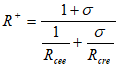
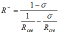
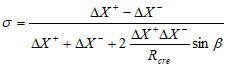
In these equations, ![]() is the normal ray; Rcre and Rcee are radii of curvatures of two paraxial wavefront: normal incident point wave and normal wave respectively;
is the normal ray; Rcre and Rcee are radii of curvatures of two paraxial wavefront: normal incident point wave and normal wave respectively; ![]() and
and ![]() are the source and receiver offsets for a given ray with respect to the central point
are the source and receiver offsets for a given ray with respect to the central point ![]() ; R+ and R are the radii of curvature of the fictitious waves defined by equations (2) and (3); V0 is the near-surface velocity; and
; R+ and R are the radii of curvature of the fictitious waves defined by equations (2) and (3); V0 is the near-surface velocity; and ![]() is a focusing parameter.
is a focusing parameter.
Our goal here is to determine the time shift for any shot and receiver in the MultiFocusing super-gather near the central point X0. According to figure 1, the moveout correction for normal ray OX0 for the trace corresponding to shot S and receiver R is given by
![]() , (4)
, (4)
Where
![]() ; (5)
; (5) ![]()
Then (6)
(6)
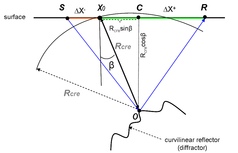
Figure 1. MultiFocusing ray diagram for diffracted wave detection.
As it follows from equation (6), diffraction moveout coincides with the MultiFocusing moveout when reflection interface shrinks to a point, i.e. when![]() .
.
So, the practical implementation of diffraction stacking is a special case of MultiFocusing.
For diffraction stacking, however, only two parameters (for 2D case) should be searched, namely ![]() and
and![]() . In the 3D case there are 5 parameters to be estimated from the data: three curvatures and two emergence angles. The parameters are estimated by maximizing the semblance function calculated for all seismic traces in the super-gather. The result of the diffraction imaging is a time section containing mostly optimally stacked diffraction events and residual specular reflections. Such sections contain important information for identifying local heterogeneities and discontinuities in the subsurface.
. In the 3D case there are 5 parameters to be estimated from the data: three curvatures and two emergence angles. The parameters are estimated by maximizing the semblance function calculated for all seismic traces in the super-gather. The result of the diffraction imaging is a time section containing mostly optimally stacked diffraction events and residual specular reflections. Such sections contain important information for identifying local heterogeneities and discontinuities in the subsurface.