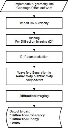
Implementation of DI project consists of several steps and applications. The general sequence of DI application shown of the block diagram below
•Import seismic data into g-Platform should include:
ocorrect geometry for source and receivers, including x, y, elevation, datum
oall statics, including elevation component applied to the gathers
oall processing sequence applied to the gathers - the best pre-PSTM gathers
ono regularization must be applied, especially CMP-consistent (5DI or similar)
odata must not include any kinematic correction applied
oModules involved:
▪[Read seg-y traces] - should be used when the input data provided from external source
▪[Read seismic traces] - should be used when the input data processed originally in g-Platform™
•Import RMS velocity field
oin order to have DI volume result correlated to the previous PSTM results, it required the the RMS velocity that will be used for DI processing will be the very same as the one used for creation of previous PSTM processing.
othe velocity should be loaded into g-Platform and include the binning information in trace headers as the input data. The actual topography and the datum of the bin points must be written in trace headers.
oModules involved:
▪[Read seg-y traces] - should be used when the input data provided from external source
▪[Read seismic traces] - should be used when the input data processed originally in g-Platform™
•Binning of seismic data
obinning must be applied to the data to allow correct values in all required trace headers
oin order to correspond to existing volumes processed outside of g-Platform, it's advised to use the very same binning parameters
oModules involved:
▪[Binning 2D]
▪[Binning 3D]
•Reflection attenuation by wavefield separation to reflection and diffraction component
oThat stage is the most crucial and require a very accurate QC.
oThe stage is responsible for modeling and attenuating reflections in the prestack data.
oPart of QC includes modeling of diffracted waves to allow visual assurance that diffraction energy was not attenuated by selected parameterization of DI
oFor geology with dipping reflections an extension of the workflow should be implemented for more accurate kinematic move-out of the data prior to wavefield separation process. That will include picking of major horizons around the target zone
oModules involved:
▪[Wave separation (HRWS)]
▪[Wave separation by gather (LPWD)]
▪[Align to Horizon]
▪[Seismic distributed loop]
▪[Seismic loop]
•Diffraction imaging responsible for focusing of diffraction events into their apexes. This flow separated into two parts.
1.Diffraction Coherency - this sub-flow creates a calibration factor for each imaging sample of DI result. The calculated semblance either calculated for each sample of imaging output volume or at any locations of imaging output volume and then interpolated according to complete output imaging dimensions.
2.Diffraction Energy - this sub-flow creates RMS amplitude of diffraction component by summation of diffraction waves
oModules involved:
▪[Engine - Diffraction Imaging 2D/3D]
▪[Imaging - Diffraction Imaging 2D/3D]
Engine - Diffraction Imaging 2D/3D:
Diffraction imaging engine calculates semblance of diffraction energy in seismic prestack data and create a database of coherency values corresponding to each sample of output volume. In other words, the algorithm focuses the diffraction location and defocusing reflection energy. The attribute identify apexes of diffraction waves and as such corresponds to disturbance in the wave-field and can allow identifying discontinuities such as faults, fractures, pinch outs and small scattering objects
In Input data tab, the user should provide the storage path. This is where all the kinematics are stored
Parameters
Storage type : Specify the storage type. 2D/3D
First azimuth(Degrees) : Provide the initial azimuth for searching the edge diffractors
Last azimuth(Degrees) : Provide the last azimuthal information for searching the edge diffractors
Half Step Azimuth (Degrees) : Specify the half step azimuth for edge diffractors search
Zero offset factor :
Minimum offset CIG(meter) : Define the minimum offset information of the Common Image Gather
Maximum Offset CIG(meter) : Define the maximum offset information of the Common Image Gather
Offset increment of CIG : Offset increment step of the Common Image Gather (CIG). Maximum offset and offset increment step size are used to limit the offset range of the input data. Consider a case where the Offset increment step is greater than the Maximum offset of the CIG then it will produce a single(1) offset plane with input data range equals to the offset step of CIG.In another case,where the Offset increment step size is less than the Maximum offset of CIG then the offset of the input data will be equal to the Maximum offset of CIG plus Offset increment step of CIG.
Aperture : Specify the migration aperture
Cross aperture :
Use full CMP aperture :
Aperture (side) : Distance from the survey edge. Aperture value will be linearly increased from 0 to maximum in this offset range from the edge. Use this parameter to minimize the migration operator artifacts along the survey edge.
Use Stretch factor : Stretch muting factor for migration aperture
Stretch factor : Factor to managing the mute zone.
Replacement velocity : Replacement velocity is used to account for topography. It is a required parameter.
Anti alias coefficient : Increasing the coefficient produces a strong filter (low frequency for far offsets).
Max freq for RHO : Maximum frequency of the output seismic data
Max angle aperture : Maximum angle aperture of the migration operator
Min angle aperture : Minimum angle aperture of the migration operator
Velocity factor : Velocity multiplier. By default 1 is used (100% velocity field used).
CMP interval along inline : Bin size along inline direction in meters/feet.
CMP interval along xline : Bin size along xline direction in meters/feet.
New Read data : By default checked.
Read bulk size : Specify the number of traces to read in a bulk.
Decimation factor : To decrease/decimate the input data by any factor. By default 1. This is very helpful when the user is testing the Edge Diffraction parameters. Instead of running the entire volume/line, can decimate the data to reduce the run time.
Migration mode :
Phase rotation : If the user prefers to do the phase rotation then they can use the options from the drop down menu.
Imaging - Diffraction Imaging 2D/3D:
This module is used to visualize the output from the Edge Diffraction Imaging 2D/3D module. Generally the user should provide the storage file as an input to Imaging - Diffraction Imaging 2D/3D module. Initially, the user can QC the diffraction imaging results of a specific inline/xline. This information should be provided to the parameters.
After initial QC, the user can export the entire volume and save it in the disk by providing the file name and path. There are multiple outputs from the Imaging - Diffraction Imaging 2D/3D module. Out of these, the user should consider the Fold and Semblance volumes for generating the Diffraction Coherency and Diffraction Energy of the diffractions.
Parameters:
Storage type : Specify the storage type i.e. 2D/3D and select from the drop down menu.
Azimuth index :
Crossline order cube export : By default unchecked. If the user checks this option, the output cube should be in Crossline order.
Visualization
Half time window normalization(ms) :
Half trace window normalizations(traces) :
Shift to datum : Check/uncheck the option to shift the datum.
Datum : In case the user chooses to shift the data to datum then specify the datum value otherwise ignore it.
Velocity : It is directly related to Shift to datum option. If the option is checked to shift the data to datum then provide the replacement velocity.
Map
Inline(Inlines) : Specify a particular inline to visualize
Crossline(Crosslines) : Specify a particular crossline to visualize
Additional gathers :
Loadfield : By default unchecked
Loadfold : By default unchecked
Full cube export
Output file name for full cube export : Specify the output file name to export the full cube
Write to sgy not calculated bins : By default unchecked. If checked, it will write the uncalculated in to SEGY.
•Output of DI results to the disk
oModules involved:
▪[Read seg-y traces] - should be used when the input data provided from external source
▪[Read seismic traces] - should be used when the input data processed originally in g-Platform™