 Post stack processing (additional noise attenuation, spectrum balance)
Post stack processing (additional noise attenuation, spectrum balance)
|
<< Click to Display Table of Contents >> Navigation: Tutorials > Seismic Processing 2D MARINE >
|
The next step after stack building is a post-stack processing which contains of two following main parts:
1) Spectral balance - increasing resolution and continuity of a seismic section;
2) Noise attenuation - improving the quality of a seismic stack by attenuation of different type of residual noise (linear, random).
Create a new workflow 0210-Post-stack-processing:
-------------------------------------Please insert image here--------------------------
The entire workflow was split into two parts (Spectral balance and noise attenuation) and looks like this:
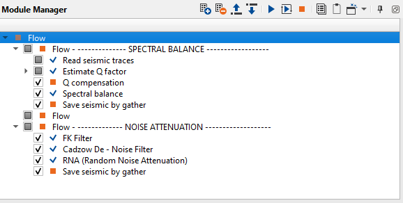
SPECTRAL BALANCE
For better solving geological purpose, spectral processing of a seismic section may be required. Especially for amplitude inversion it is a requirement to prepare stacked data with the broadest bandwidth and the flattest spectrum. Hence, a processing sequence tailored for the amplitude inversion almost always includes post-stack deconvolution, Q compensation or spectral whitening steps. We will use two modules for spectral balancing: Q compensation and Spectral balance.
------------------------------------------------------------------------------------------------------------
Notice: Using Q-compensation is better for pre-stack data and before deconvolution.
In current project we decided do not use Q-compensation for pre-stack data.
-------------------------------------------------------------------------------------------------------------
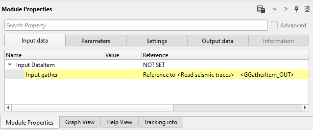
Load the stack 0190-Stack from previous step into RAM using Read seismic trace module and connect Input gather field to input stack.
1. Read seismic traces - load stack
2. Estimate Q factor - Q estimation
3. Q compensation - increase absorbed frequencies
4. Spectral balance - bandwidth widening
5. Save seismic by gather - save seismic stacked traces
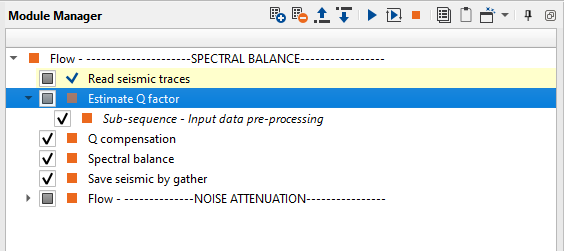
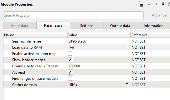
1) Read seismic traces. Load the stack 0190-Stack into RAM.
Parameters:
2) Estimate Q factor. Q attenuation is the absorption of energy caused by the fact that seismic wave going through the earth and lost its energy. Q factor describes the ratio of retained energy to lost energy over a single wavelength. To restore this energy we can apply Q compensation algorithm by using a constant Q-value from well data or use calculated Q-model by Estimate Q factor module. We are going to use Q-model, choose appropriate time window.
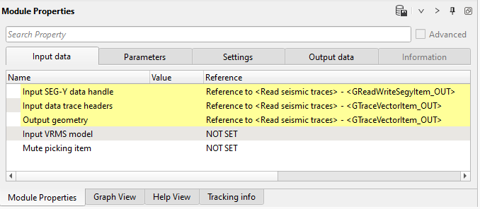
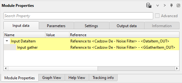
Get all necessary input data items from Read seismic traces:
Input data:
Parameters:
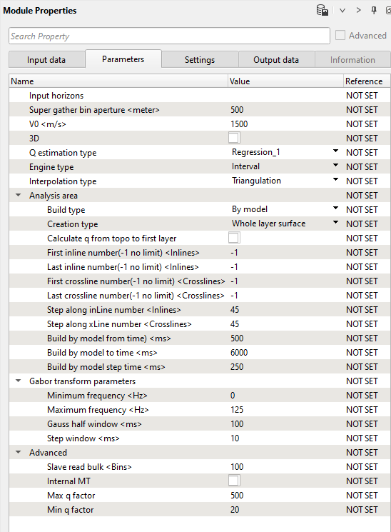
Execute the module and open vista window: Q-model window, pay attention there is no vista groups, so use Vista in context menu (Q-int gather out):
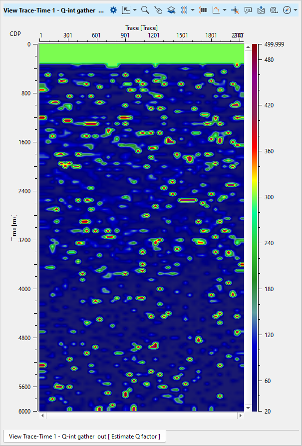
Obviously, the result is not smoothed, so try to change some of the main parameters for Q estimation. For instance, Q estimation type = Average, Engine type = RMS, Interpolation type = Voronoi, First crossline number(-1 no limit) <Crosslines> = 100, Last crossline number(-1 no limit) <Crosslines> = 2000. Execute estimation again and check the result:
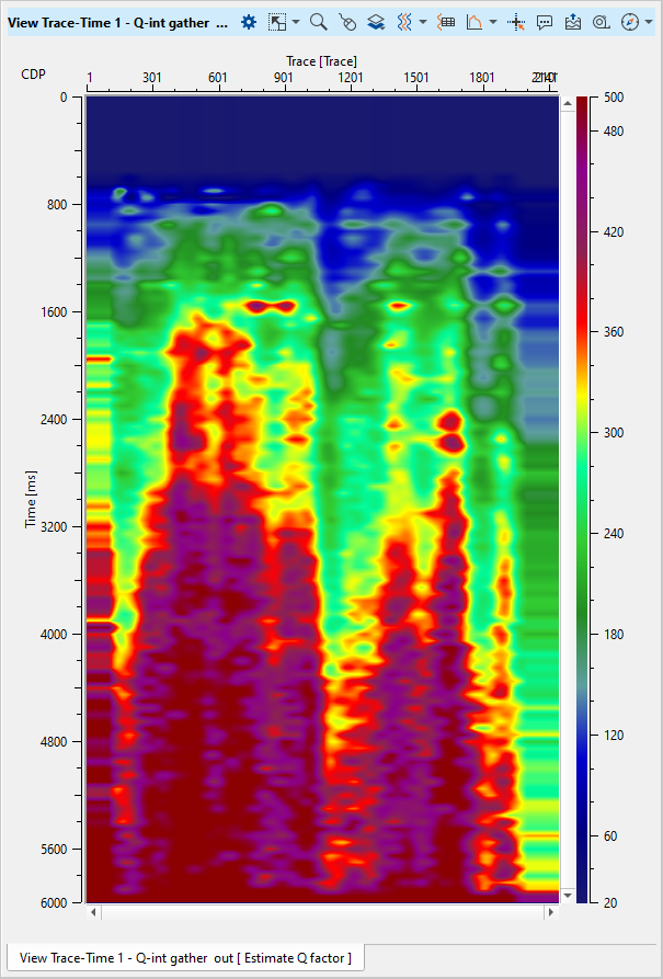
Play with the parameters and choose the most appropriate. Also, we can apply additional smooth for Q-model by using Smooth 2D module.
The following result was calculated with those parameters:
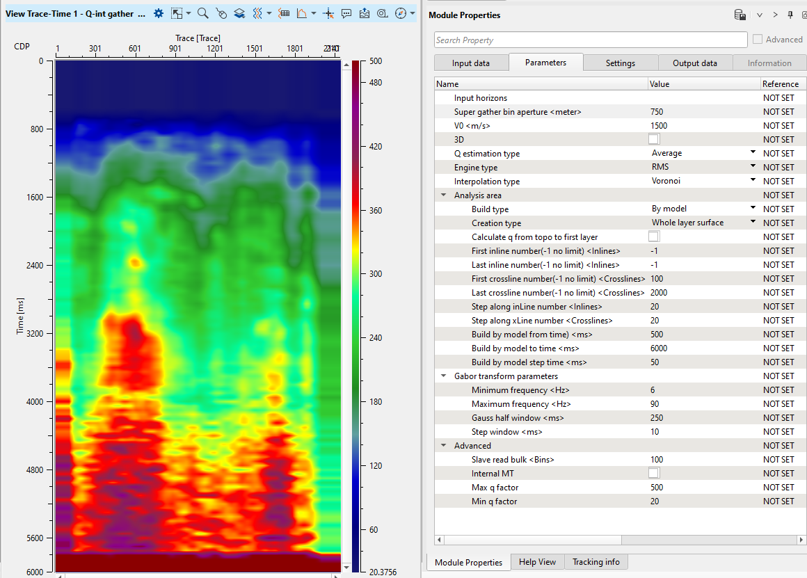
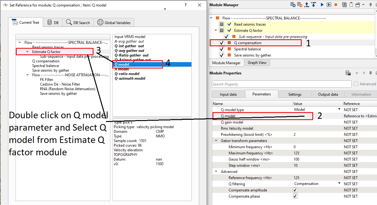
3) Q compensation. Then add Q compensation module for Q-model applying. Define input data items and parameters. In the parameters tab we should define Q-model: double click on Q model in the parameters, in the pop-up window select Estimate Q factor module -> Q - int gather out -> Ok.
Input data:
Parameters:
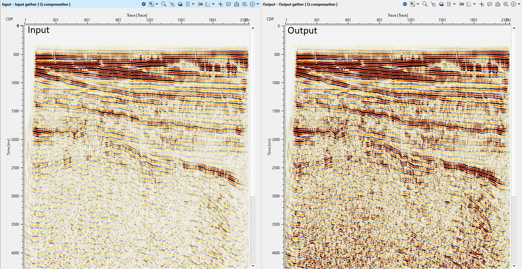
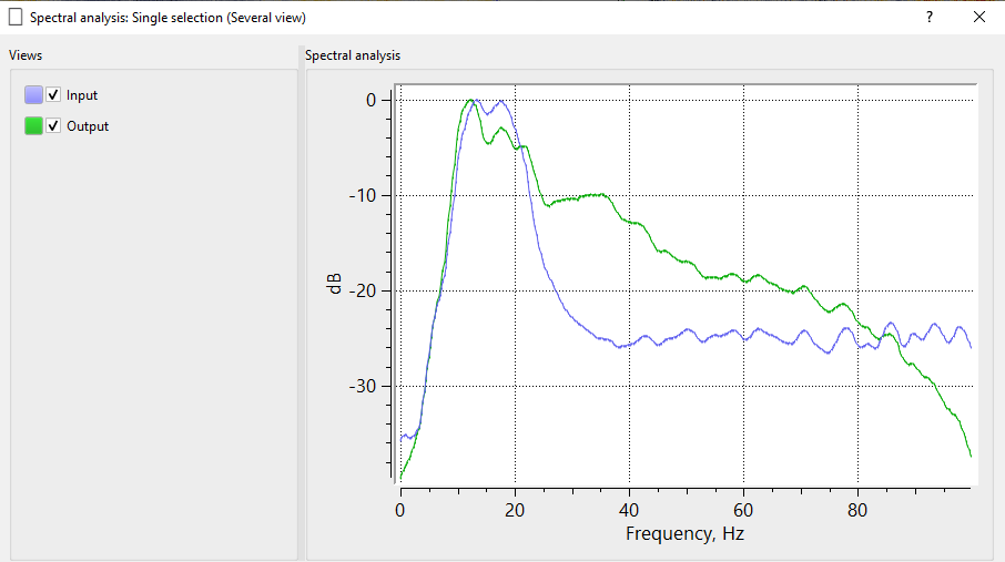
Execute the module and open input and output vista windows, compare two stacks. Optionally, estimate amplitude-frequency spectrum ![]() in different time windows (upper part of the stack section, deeper part).
in different time windows (upper part of the stack section, deeper part).
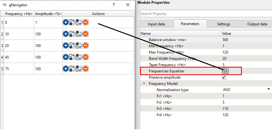
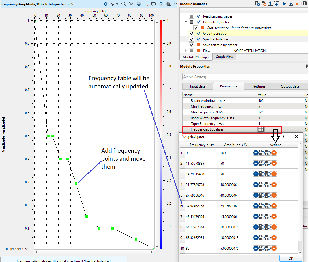
4) Spectral balance splits the seismic data into frequency bands, performs a transparent AGC on each of the bands. Then those decomposition is set to a predetermined amplitude level and finally, bandwidth are merged to rebuild the original trace. Use narrow bandwidth for better flattering frequency spectra, and frequency equalizer for accurate managing frequency recovery. Define parameters:
Parameters:
Open vista groups, go to the Frequency-Amplitude/DB - Total spectrum and draw a desired spectrum as shown below:
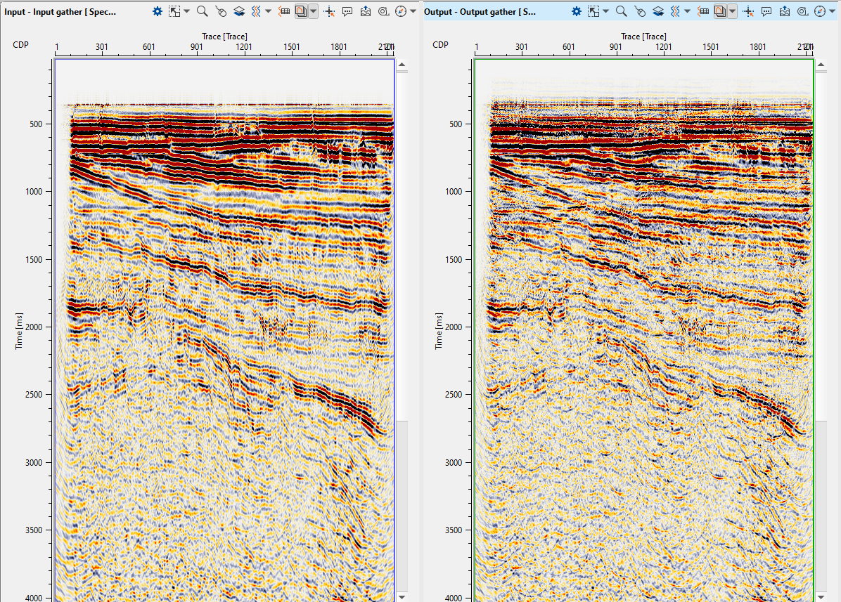
Execute the module and check stack before and after spectrum balancing, estimate its amplitude-frequency spectrum ![]() in the target interval:
in the target interval:
5) Save seismic by gather. Write a name for the output data set 0200-Stack-balanced and execute the module.
NOISE ATTENUATION
Final step in the processing is post-stack noise attenuation or in other words it is stack enhancement stage. There are a few steps: linear noise attenuation, migration operator artifacts removal, random noise attenuation and horizon continuity improving (coherent filters).
The second part of the workflow is for post-stack denoise:
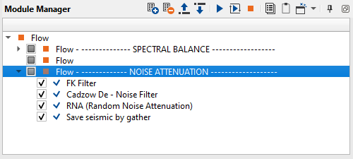
1. FK Filter - linear denoise
2. Cadzow De - Noise Filter - random denoise
3. RNA (Random Noise Attenuation) - linear denoise
4. Save seismic by gather - save seismic stacked traces
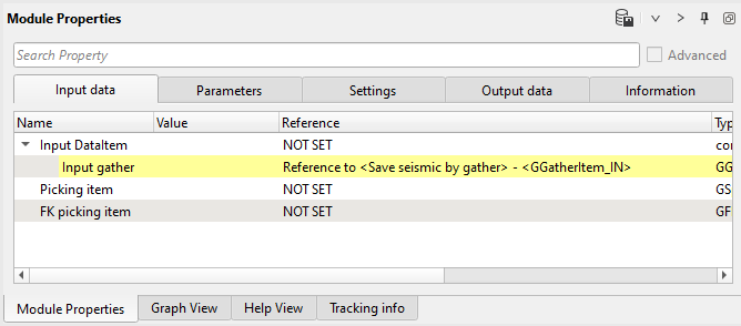
1) FK Filter. The same module that we already used in previous steps: this module applies an FK filter. FK transforms 2D data to frequency-wave number space. The user can then define a mute zone in that space to apply an FK filter. There are several modules for linear denoise we can use: FK Filter, LNA, Radon Tau-P modules. All this modules can produce similar results, so what to use depends on geophysicist or client preferences. We will use FK FIlter.
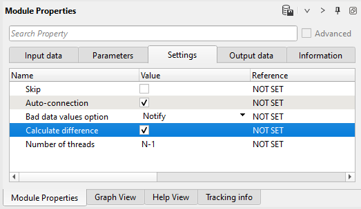
Connect input seismic data item from the first part of the workflow, define parameters, select difference calculation in the Settings tab:
Input data:
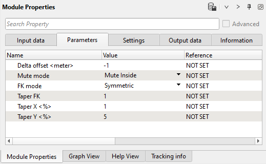
Parameters:
Settings:
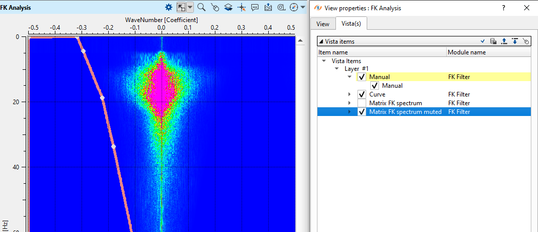
Open FK vista window and draw a mute polygon as shown below:
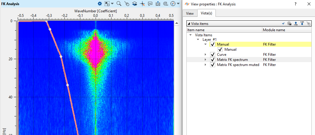
Check muted spectrum, we use symmetric mode ( look at the Parameters tab):
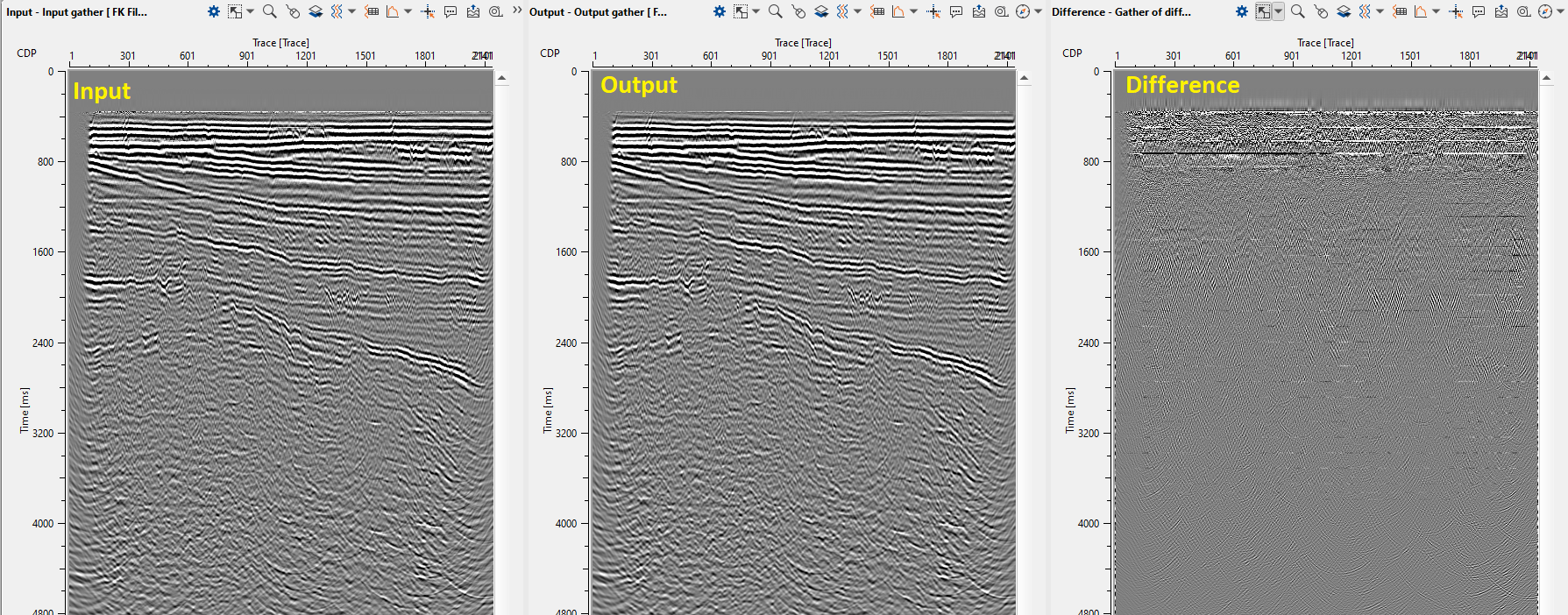
Execute the module and open input and output stack windows:
--------------------------------------------------------------------------------------------------------------------------
Notice! You can flatten horizon and apply denoise procedure for better dip preserving, as well as
cut seismic trace into several parts (0-1000 ms, 1000-2000 ms, 2000-3000 ms) and apply different
procedures for particular time windows or bandwidth, and then merge them back.
--------------------------------------------------------------------------------------------------------------------------
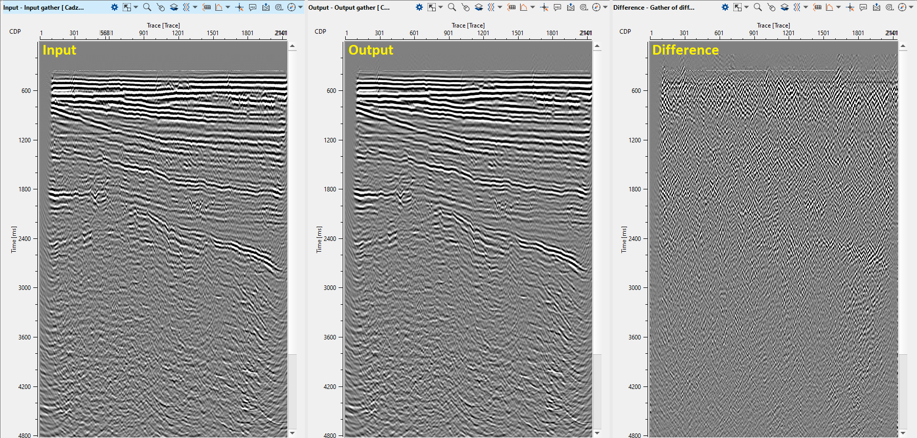
2) Cadzow De - Noise Filter. There are several modules for random denoise: RNA (Random Noise Attenuation), SVD Denoise filter, Cadzow De – Noise Filter, FX-Decon filter modules. Those filters have similar algorithms, parameters, results, but difference is in the domain which is used for seismic data transformation. Therefore, we will use Cadzow De – Noise Filter and RNA (Random Noise Attenuation). This module attenuates the incoherent noise from the seismic data that is not linearly predictable after transform a seismic data into FX-domain.
Input data:
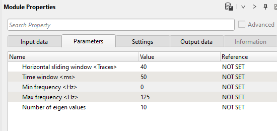
Parameters:
Settings:
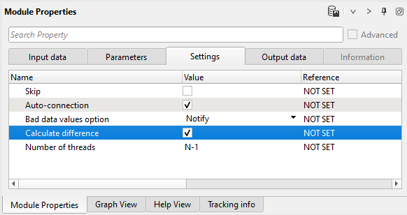
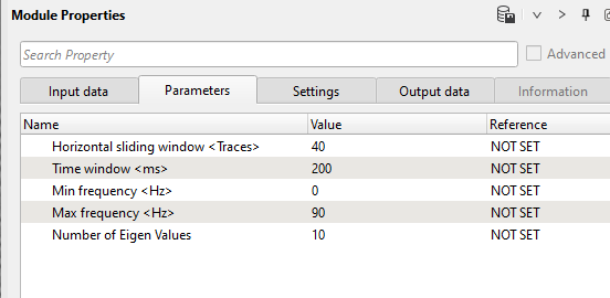
Parameters definition:
•Horizontal sliding window <tr> - number of input traces for filter prediction;
•Time window <ms> - length of the time window;
•Min frequency <Hz> - the minimum frequency value to transform;
•Max frequency <Hz> - the maximum frequency value to transform;
•Number of eigen values - seismic data matrix construction accuracy; the lesser the number the harsher the reduction of noise.
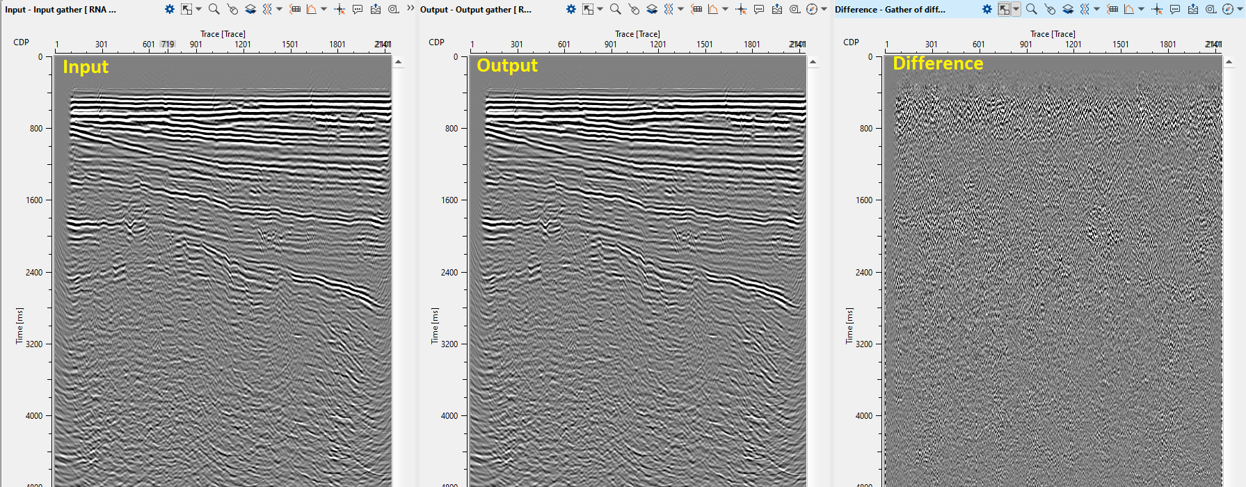
Execute the module and open stack windows (input, output and difference). Pay attention on dip events, if it is damaged, try to change parameters (softer):
3) RNA (Random Noise Attenuation). RNA module attenuates or reduces the incoherent noise from the seismic data that is not linearly predictable. It can be applied on shot domain gathers, CDP gathers or stacked data. Random Noise Attenuation improves the coherency of the Shot/CDP gathers or Stack image.
Input data:
Parameters:
Settings:
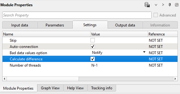
Parameters definition:
•Horizontal sliding window <tr> - number of input traces for filter prediction;
•Time window <ms> - length of the time window;
•Min frequency <Hz> - the minimum frequency value to transform;
•Max frequency <Hz> - the maximum frequency value to transform;
•Number of eigen values - seismic data matrix construction accuracy; the lesser the number the harsher the reduction of noise, usually 1-3.
Execute the module and open stack windows (input, output and difference). Pay attention on dip events, if it is damaged, try to change parameters (softer):
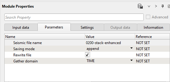
5) Save seismic by gather. Write a name for the output data set 0200-Stack-enhanced and execute the module.
Parameters:
 If you have any questions, please send an e-mail to: support@geomage.com