 AVO attributes and angle stacks
AVO attributes and angle stacks
|
<< Click to Display Table of Contents >> Navigation: Tutorials > Seismic Processing 2D MARINE >
|
Amplitude versus offset (AVO) is the general term for referring to the dependency of the amplitude, with the distance between the source and receiver (the offset). AVO analysis is a technique that geophysicists can execute on seismic data to determine a rock's fluid content, porosity, density or seismic velocity, shear wave information, fluid indicators (hydrocarbon indications). The most important application of AVO is the detection of hydrocarbon reservoirs. Increasing AVO is usually present in oil-bearing sediments with at least 10% gas saturation, but is especially pronounced in porous, low-density gas-bearing sediments with little to no oil.
There are two modules to perform AVO analysis in g-Platform. First is Angle stack module to compute angle stacks and second is AVA module to compute AVO attributes.
Create a new workflow 0220-AVO-and-angle-stacks:
--------------------Please insert image here--------------------
The entire workflow was split into several parts and looks like this:
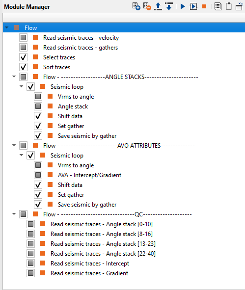
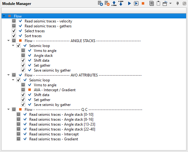
1. Read seismic traces - velocity - load velocity
2. Read seismic traces - gathers - load gathers after additional denoise
3. Select traces - selecting traces
4. Sort traces - sorting traces
----------------------------- ANGLE STACKS ----------------------------
5. Seismic loop - process every gather in the loop
6. Vrms to angle - convert velocity into angles
7. Angle stack - process every gather in the loop
8. Shift data - move seismic to the final datum
9. Set gather - accumulate stacked traces
10. Save seismic by gather - save angle stacks
---------------------------- AVO ATTRIBUTES --------------------------
11. Seismic loop - process every gather in the loop
12. Vrms to angle - convert velocity into angles
13. AVA - intercept / gradient - process every gather in the loop
14. Shift data - move seismic to the final datum
15. Set gather - accumulate stacked traces
16. Save seismic by gather - save intercept and gradient
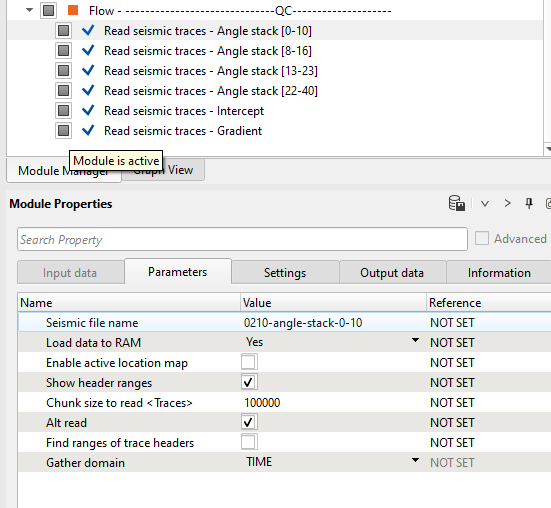
-------------------------------------- QC ------------------------------------
17. Read seismic traces - Angle stack [0-10]
18. Read seismic traces - Angle stack [8-16]
19. Read seismic traces - Angle stack [13-23]
20. Read seismic traces - Angle stack [22-40]
21. Read seismic traces - Intercept
22. Read seismic traces - Gradient
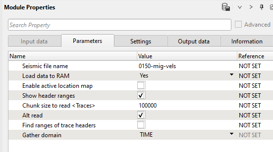
1) Read seismic traces - velocity. Load 0150-mig-vels into RAM.
Parameters:
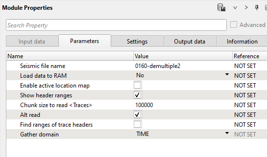
2) Read seismic traces - gather. Load seismic gathers 0160-demultiple2
Parameters:
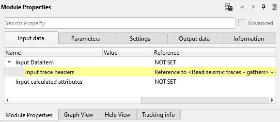
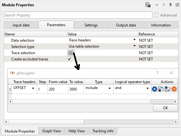
3) Select traces. Remove bad near offset for AVO analyze, because it has harsh print from the near offset noise, that quite difficult to remove completely. So. we need to add trace header selection by using OFFSET header (200-3000 meters).
Input data:
Parameters:
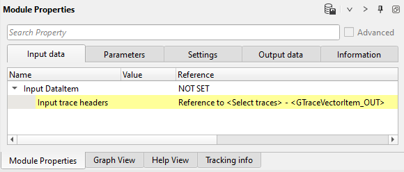
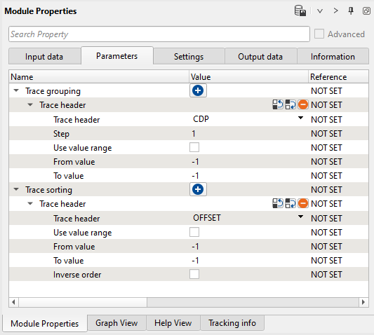
4) Sort traces. Sort seismic traces for Seismic loop, set CDP-OFFSET header for sorting.
Input data:
Parameters:
ANGLE STACKS
5) Seismic loop. Connect trace headers vector (Input sorted headers) from the Sort traces module output and seismic (Input SEG-Y data handle) from Read seismic traces - gather.
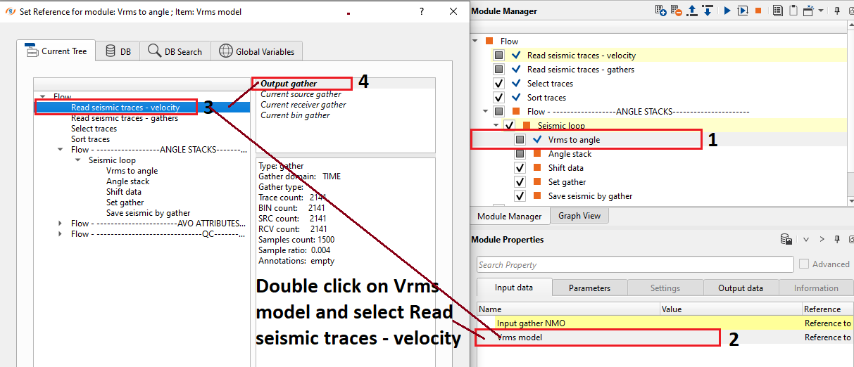
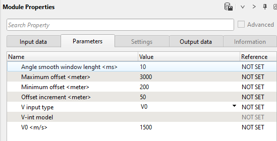
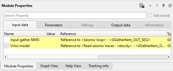
6) Vrms to angle module create angles from velocity. Specify minimum/maximum offsets and offsets increment according to the CIG gathers after migration.
Define input data items: select velocity Vrms from Read seismic traces.
Parameters:
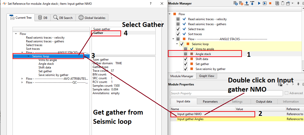
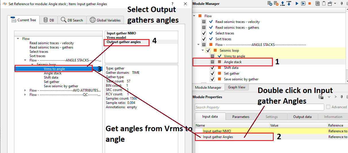
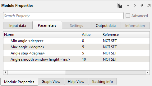
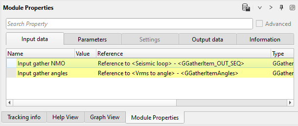
7) Angle stacks divides CIG gathers into angle groups for further stacking on the next step. Angles are specified in parameters.
Define input data items:
Parameters: pay attention on Angle step as well, for example if we define 0-5 range, then Angle step must be 5.
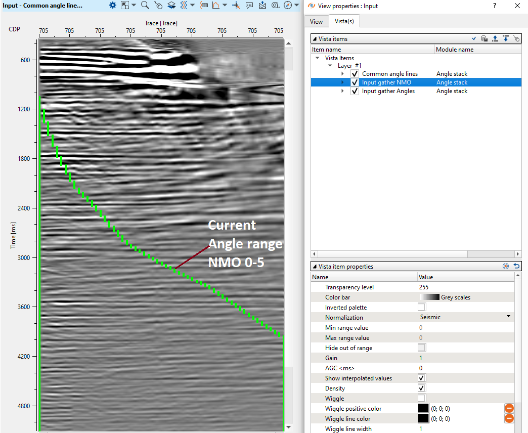
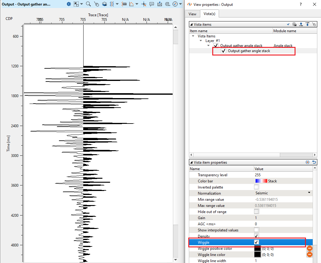
Execute those three modules and open vista groups of Angle stack module and check current (0-5) angle range on the CIG gather:
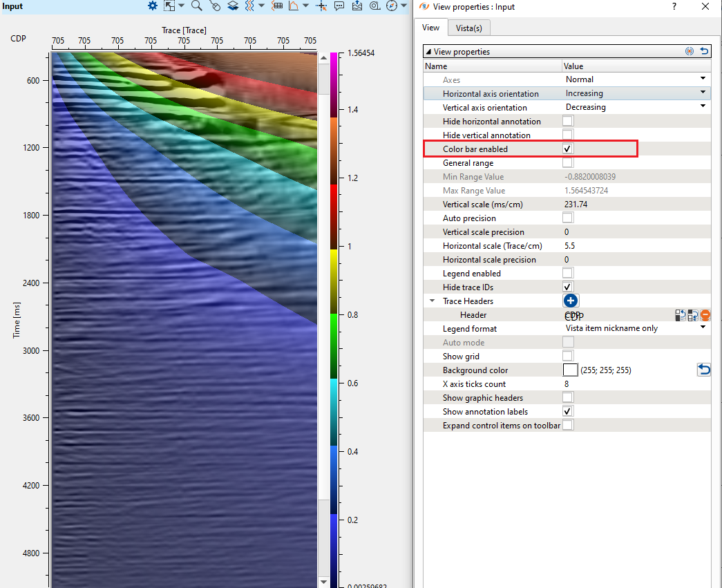
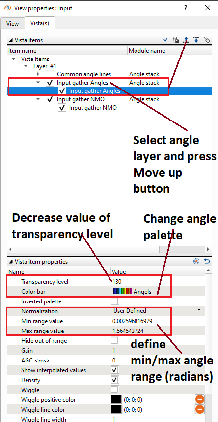
Look at the angle layer:
Go to the Output gather angle stack window to check 1 stacked trace. Change density color type into wiggle one to see 1 trace:
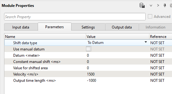
8) Shift data module moves traces to the final (const) datum plane. Choose Shift data type - To datum and specify Datum and replacement Velocity:
Parameters:
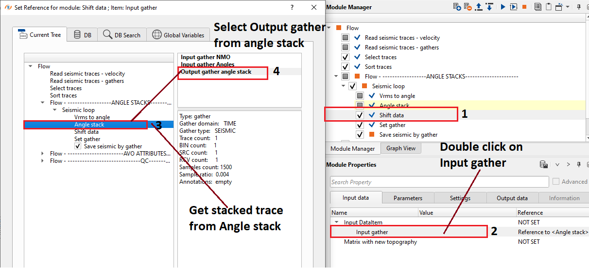
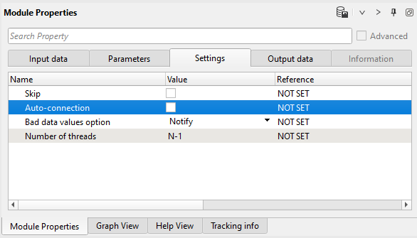
Pay attention! that Seismic loop makes auto-connection between modules, so in this case we have to turn-off Auto-connection option in order to get appropriate input data item.
Get output gather manually:
Settings:
9) Set gather accumulates traces for stack viewing. There is no any parameters.
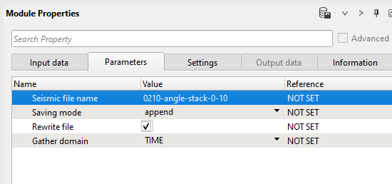
10) Save seismic by gather. Write a name for the first angle stack set 0210-angle-stack-0-10 and execute the entire Seismic loop.
Parameters:
Now we have only one angle stack (0-10), therefore let's create other angle stacks. Go back to the Angle stack module, change angle and step range, then change a name for output angle stack to 0210-angle-stack-4-16 and execute the entire Seismic loop, and so on repeat it for rest of stacks: 0210-angle-stack-13-23, 0210-angle-stack-22-40. Angle range should choose interpreter specialist based on angle stack fold distribution and AVO analysis.
AVO ATTRIBUTES
11) Seismic loop. Connect trace headers vector (Input sorted headers) from the Sort traces module output and seismic (Input SEG-Y data handle) from Read seismic traces - gather.
12) Vrms to angle module create angles from velocity. Specify minimum/maximum offsets and offsets increment according to the CIG gathers after migration.
Define input data items, make the same connections as it was on the previous step (angle stacks):
Input data:
Parameters:
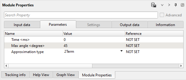
13) AVA specify Max angle and Approximation type and run module to create Intercept and Gradient attributes.
Input data:
Parameters:
14) Shift data module moves traces to the final (const) datum plane. Choose Shift data type - To datum and specify Datum and replacement Velocity:
Parameters:
Pay attention! that Seismic loop makes auto-connection between modules, so in this case we have to turn-off Auto-connection option in order to get appropriate input data item. Do manual connection like you have done before (angle stack flow):
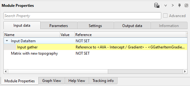
Input data:
Settings:
15) Set gather accumulates traces for stack (R0, Gradient) viewing. There is no any parameters.
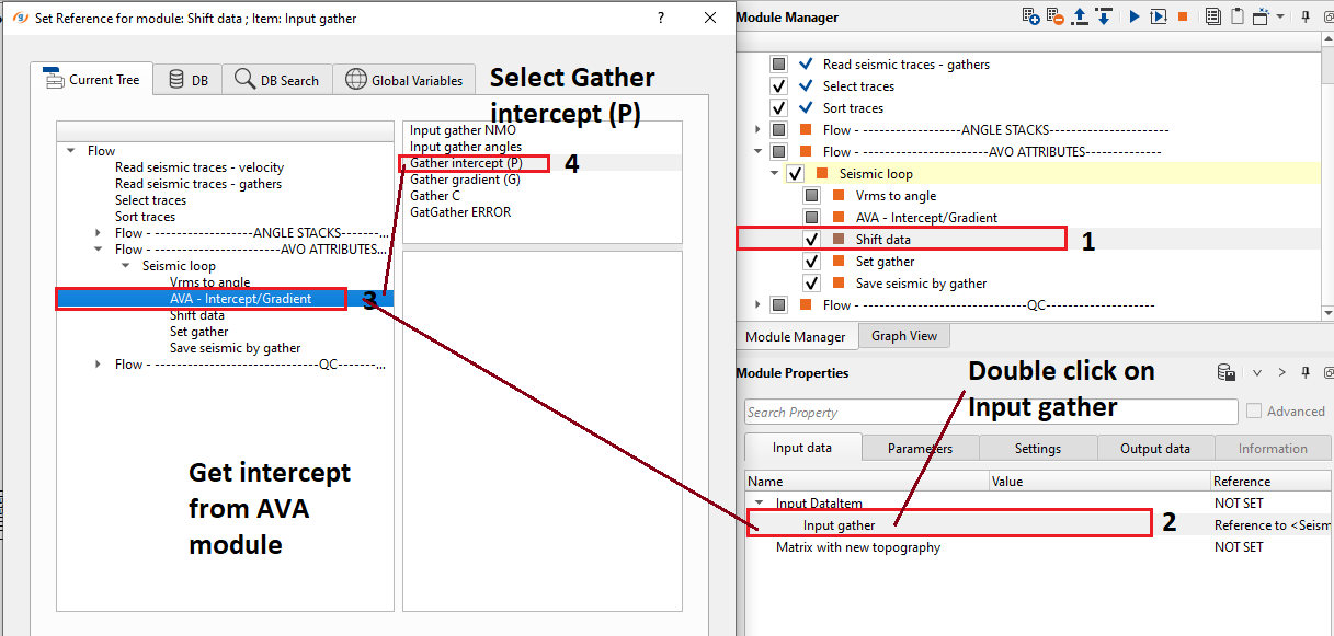
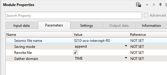
16) Save seismic by gather. Write a name for the intercept attribute 0210-avo-intercept-R0 and execute the entire Seismic loop.
Parameters:
Now we have only one AVO attribute: Intercept, therefore let's create Gradient. Go back to the Shift module and change input data item connection:
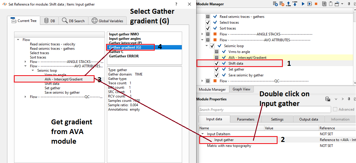
Write a name for the gradient attribute 0210-avo-gradient and execute the entire Seismic loop.
QUALITY CONTROL
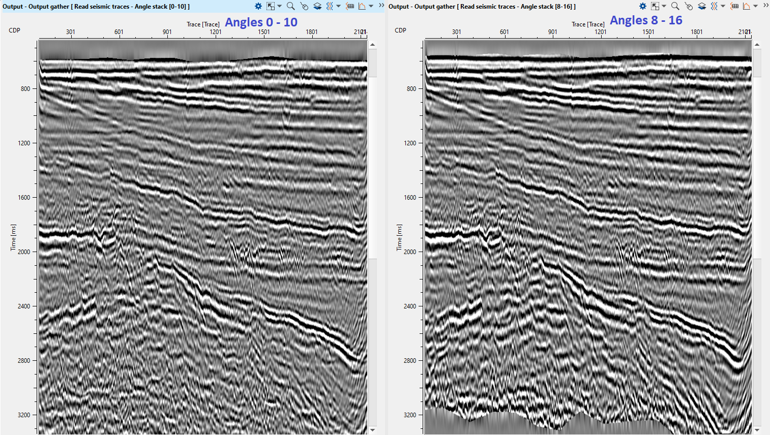
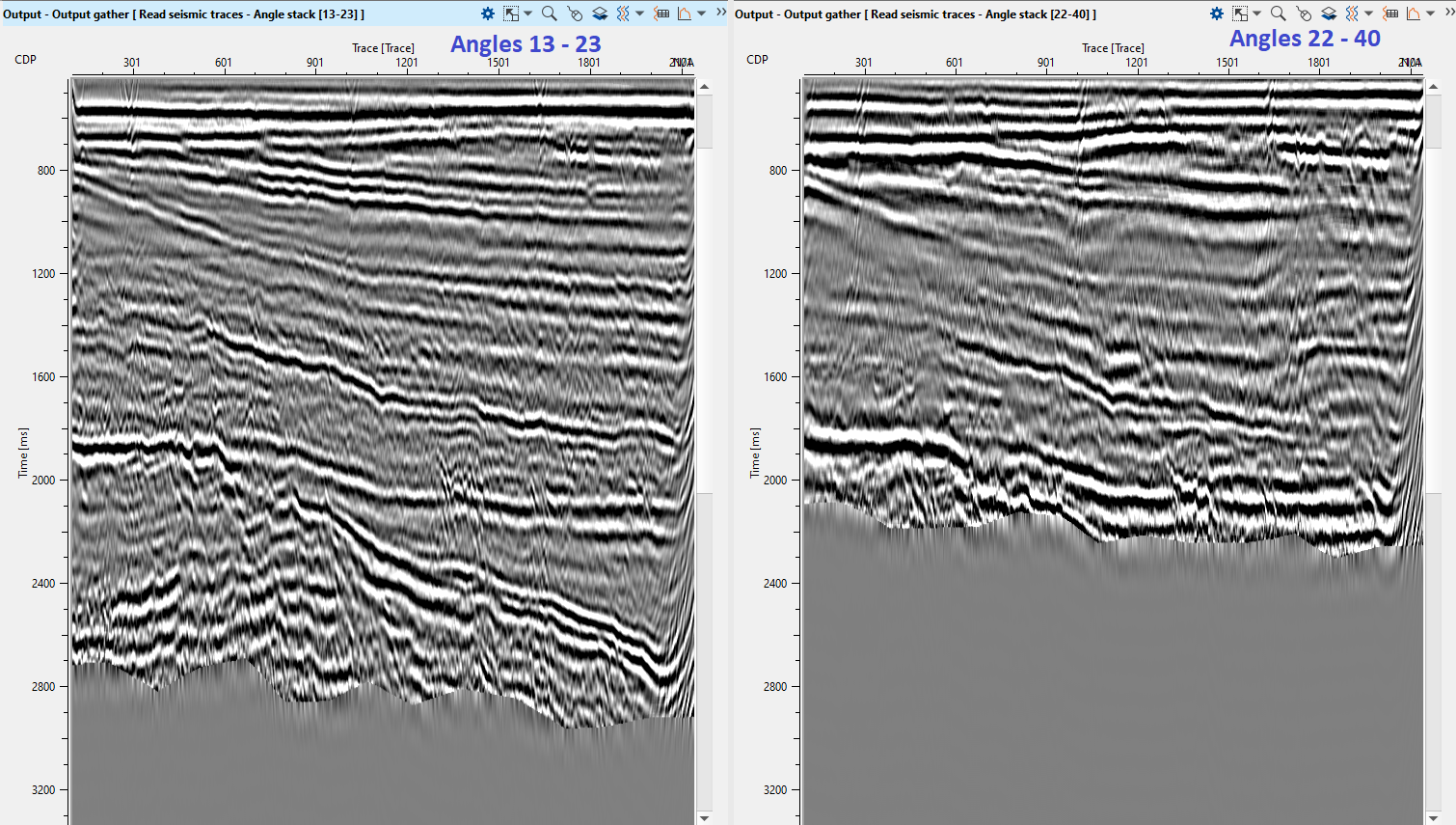
Now we can look at angle stacks and AVO attributes. Of course it is better to see angle stacks exactly when you calculate it, and not like we are doing it now in the end of the workflow. We could read angle stack on each calculation iteration or use Set gather module, but for current workflow looks quite accurate :) just for ease visual acceptability.
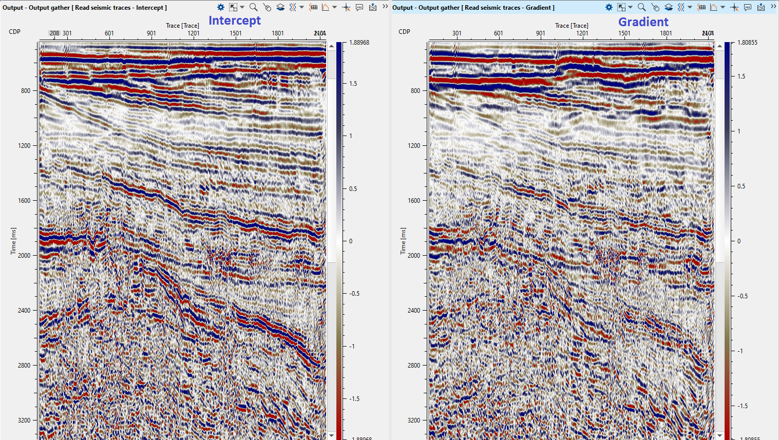
Read all seismic stacks: angles and AVO attributes, load them into RAM and open Output stack section window:
Angle stacks:
AVO attributes:
 If you have any questions, please send an e-mail to: support@geomage.com