 POST-STACK PROCESSING
|
<< Click to Display Table of Contents >> Navigation: Tutorials > Seismic Processing 3D LAND >
|
The next step after stack building is a post-stack processing which contains of two following main parts:
1) Spectral balance - increasing resolution and continuity of a seismic section;
2) Noise attenuation - improving the quality of a seismic stack by attenuation of different type of residual noise (linear, random).
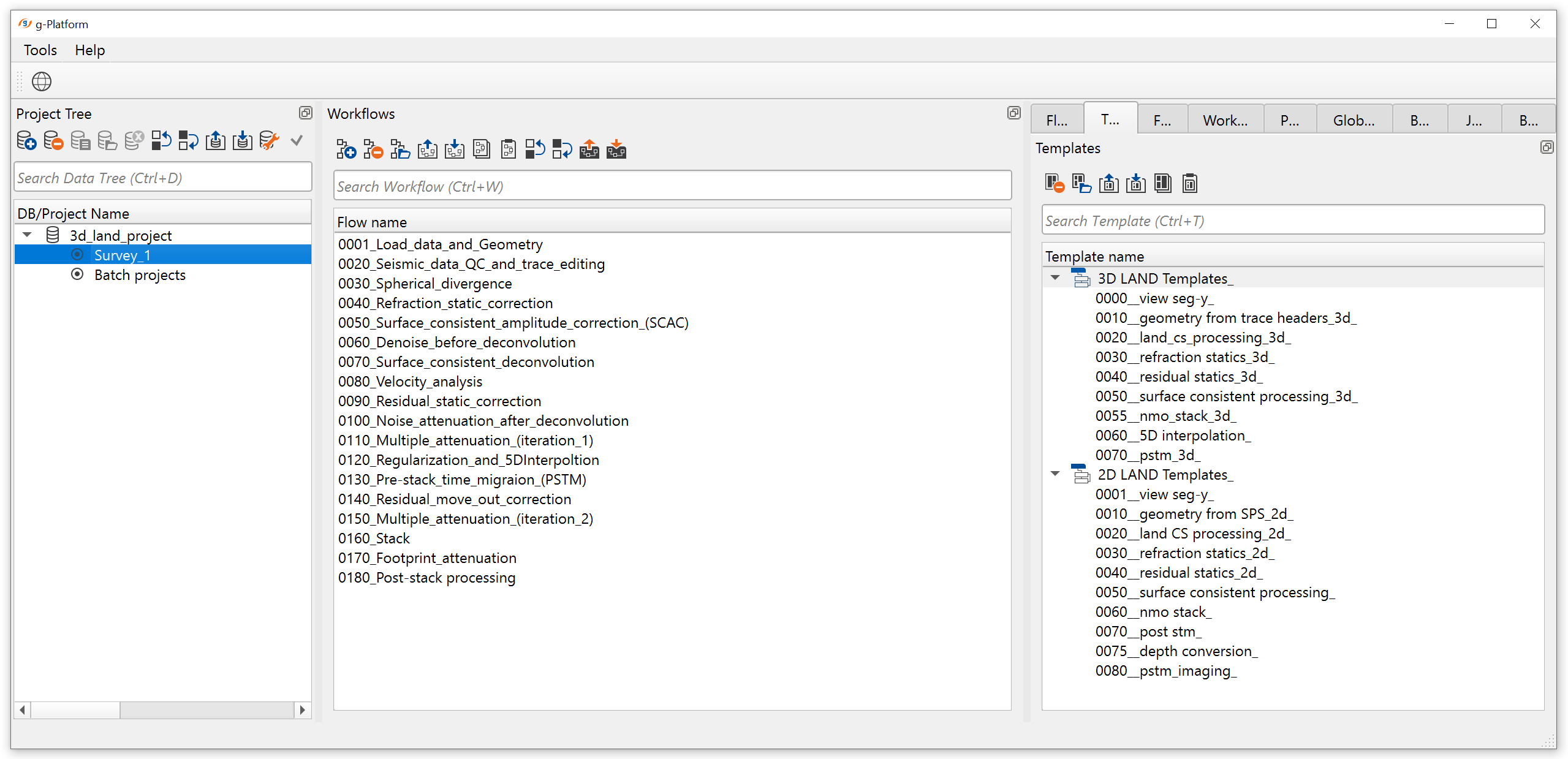
Create a new workflow 0180_Post-stack_processing:
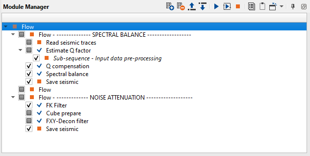
The entire workflow was split into two parts (Spectral balance and noise attenuation) and looks like this:
SPECTRAL BALANCE
For better solving geological purpose, spectral processing of a seismic section may be required. Especially for amplitude inversion it is a requirement to prepare stacked data with the broadest bandwidth and the flattest spectrum. Hence, a processing sequence tailored for the amplitude inversion almost always includes post-stack deconvolution, Q compensation or spectral whitening steps. We will use two modules for spectral balancing: Q compensation and Spectral balance.
------------------------------------------------------------------------------------------------------------
Notice: Using Q-compensation is better for pre-stack data and before deconvolution.
In current project we decided do not use Q-compensation for pre-stack data.
-------------------------------------------------------------------------------------------------------------
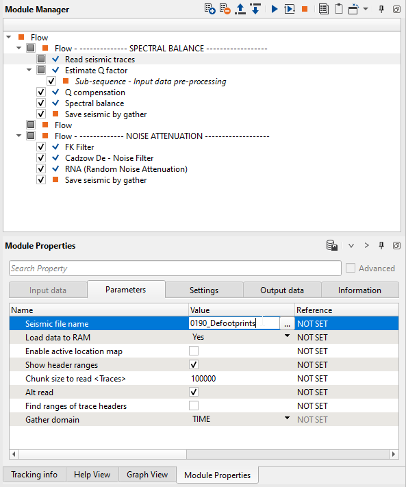
Load the stack 0190_Defootrpints from previous step into RAM using Read seismic trace module and connect Input gather field to input stack.
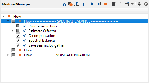
1. Read seismic traces - load stack
2. Estimate Q factor - Q estimation
3. Q compensation - increase absorbed frequencies
4. Spectral balance - bandwidth widening
5. Save seismic by gather - save seismic stacked traces
1) Read seismic traces. Load the stack 0190_Defootrpints into RAM.
Parameters:
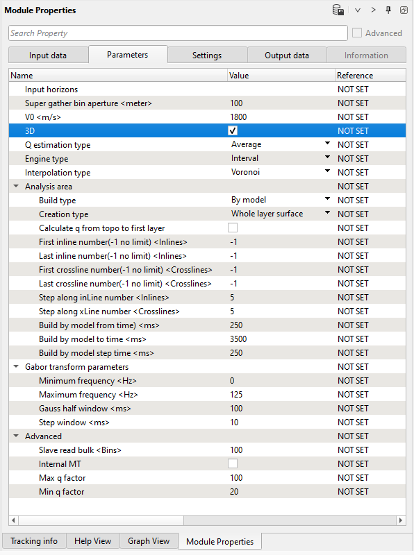
2) Estimate Q factor. Q attenuation is the absorption of energy caused by the fact that seismic wave going through the earth and lost its energy. Q factor describes the ratio of retained energy to lost energy over a single wavelength. To restore this energy we can apply Q compensation algorithm by using a constant Q-value from well data or use calculated Q-model by Estimate Q factor module. We are going to use Q-model, choose appropriate time window.
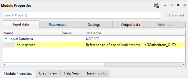
Get all necessary input data items from Read seismic traces:
Input data:
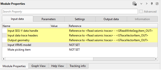
Parameters:
Execute the module and open vista window: Q-model window, pay attention there is no vista groups, so use Vista in context menu (Q-int gather out):
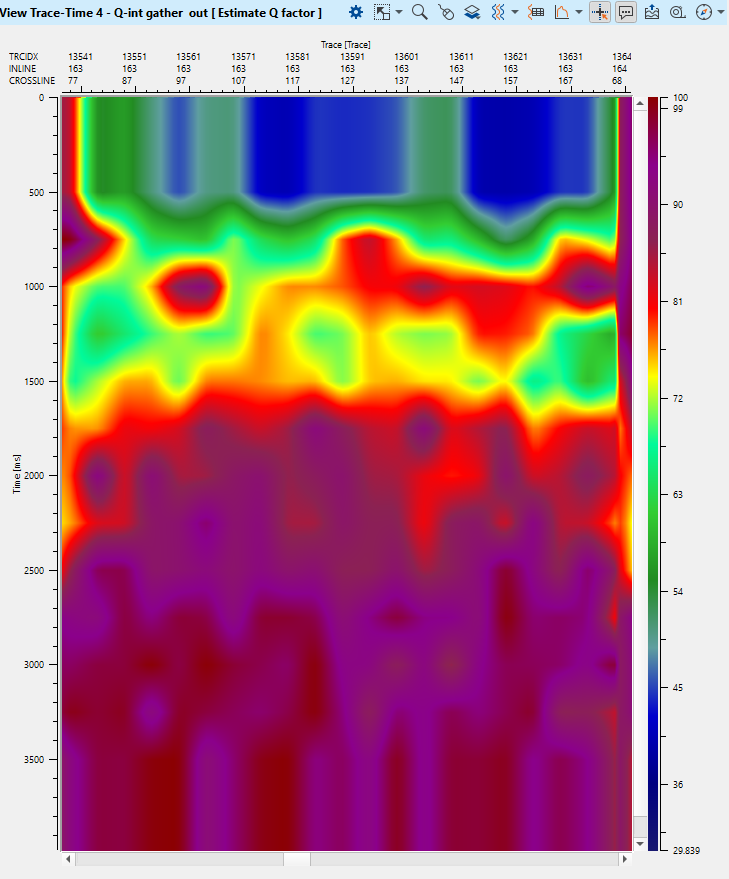
Notice that we can smooth Q-model is it necessary.
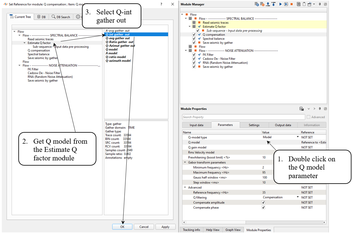
3) Q compensation. Then add Q compensation module for Q-model applying. Define input data items and parameters. In the parameters tab we shuld define Q-model: double click on Q model in the parameters, in the pop-up window select Estimate Q factor module -> Q - int gather out -> Ok.
Input data:
Parameters:
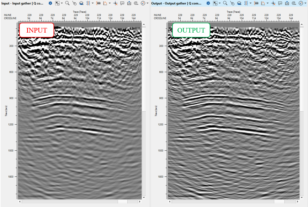
Execute the module and open input and output vista windows, compare two stacks. Optionally, estimate amplitude-frequency spectrum ![]() in different time windows (upper part of the stack section, deeper part).
in different time windows (upper part of the stack section, deeper part).
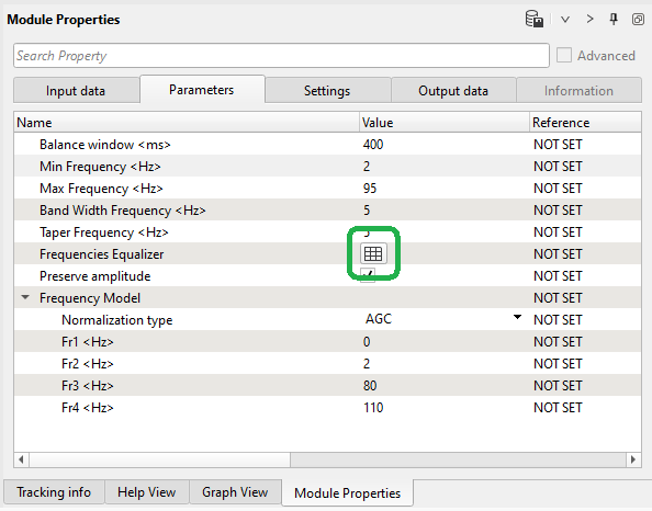
4) Spectral balance splits the seismic data into frequency bands, performs a transparent AGC on each of the bands. Then those decomposition is set to a predetermined amplitude level and finally, bandwidth are merged to rebuild the original trace. Use narrow bandwidth for better flattering frequency spectra, and frequency equalizer for accurate managing frequency recovery. Define parameters:
Parameters:
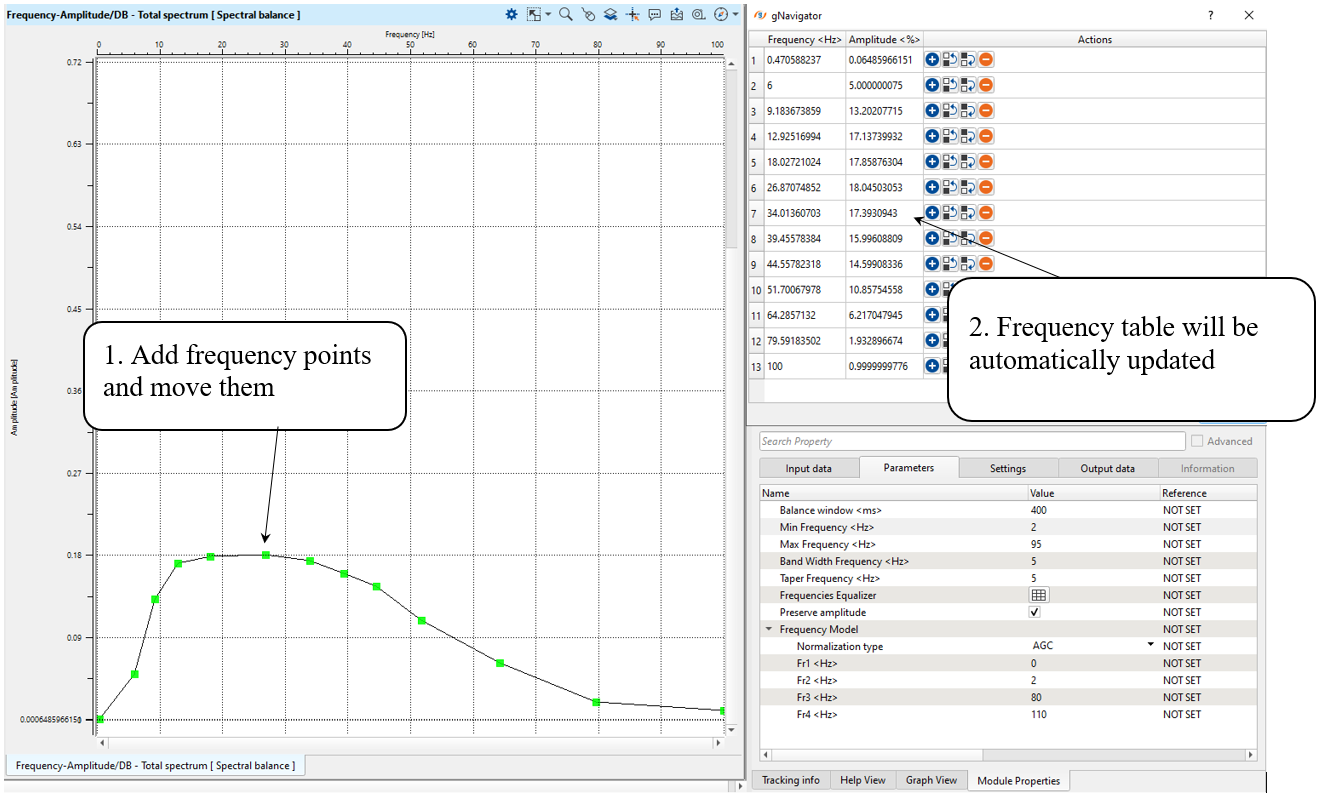
Open vista groups, go to the Frequency-Amplitude/DB - Total spectrum and draw a desired spectrum as shown below:
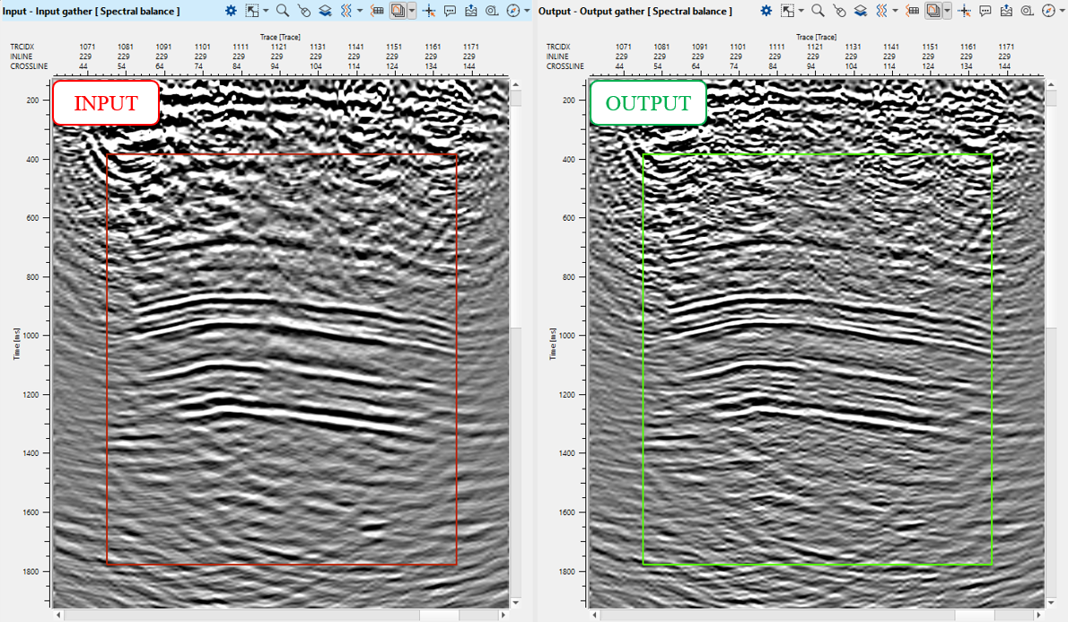
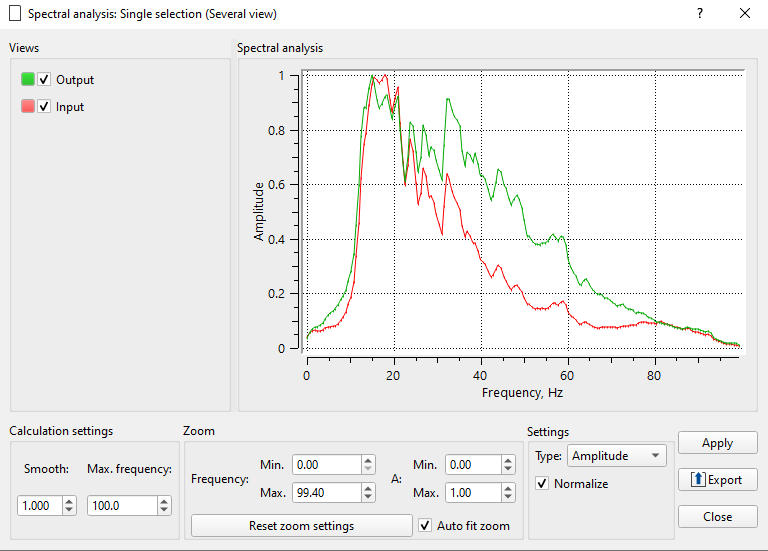
Execute the module and check stack before and after spectrum balancing, estimate its amplitude-frequency spectrum ![]() in the target interval:
in the target interval:
5) Save seismic by gather. Write a name for the output data set 0200_Stack_balanced and execute the module.
NOISE ATTENUATION
Final step in the processing is post-stack noise attenuation or in other words it is stack enhancement stage. There are a few steps: linear noise attenuation, migration operator artifacts removal, random noise attenuation and horizon continuity improving (coherent filters).
The second part of the workflow is for post-stack denoise:
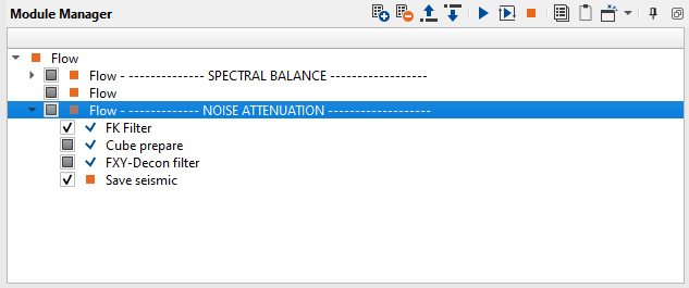
1. FK Filter - linear denoise
2. Cube prepare - cube format preparation for FXY-Decon filter
2. FXY-Decon filter - 3D random denoise
4. Save seismic by gather - save stack seismic cube
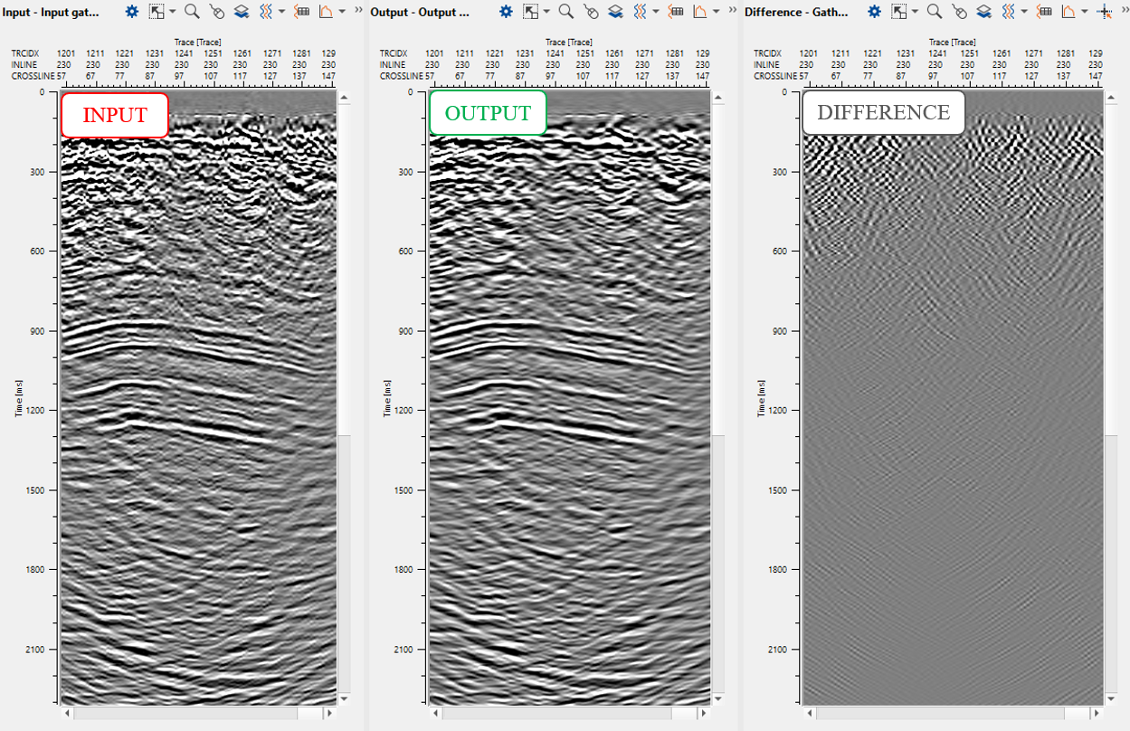
1) FK Filter. The same module that we already used in previous steps: this module applies an FK filter. FK transforms 2D data to frequency-wave number space. The user can then define a mute zone in that space to apply an FK filter. There are several modules for linear denoise we can use: FK Filter, LNA, Radon Tau-P modules. All this modules can produce similar results, so what to use depends on geophysicist or client preferences. We will use FK Filter. Also, be careful with FK peocedure, because it could damage signal (dips, folds area), so it is better to apply medium FK to the upper part where there is no (usually) complex geological structures, and apply very soft FK to dipper part of the seismic stack section.
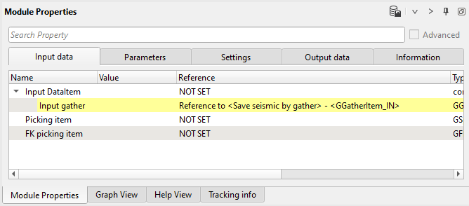
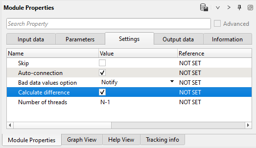
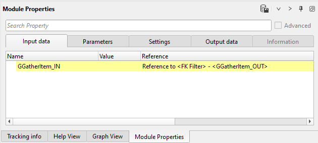
Connect input seismic data item from the first part of the workflow, define parameters, select difference calculation in the Settings tab:
Input data:
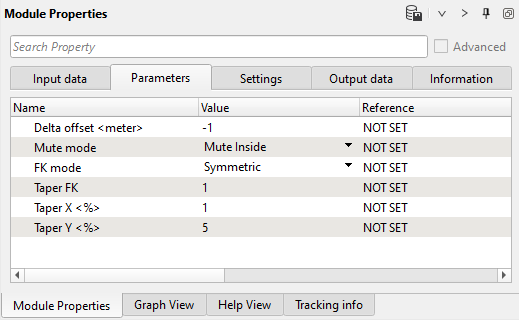
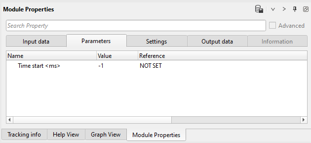
Parameters:
Settings:
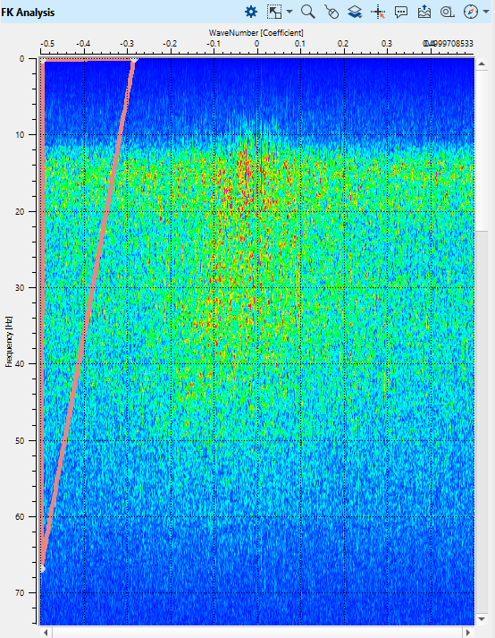
Open FK vista window and draw a mute polygon as shown below:
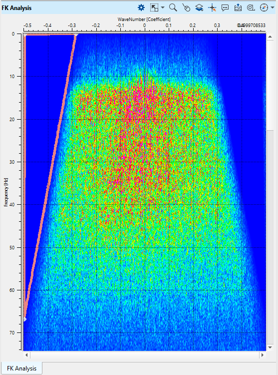
Check muted spectrum, we use symmetric mode ( look at the Parameters tab):
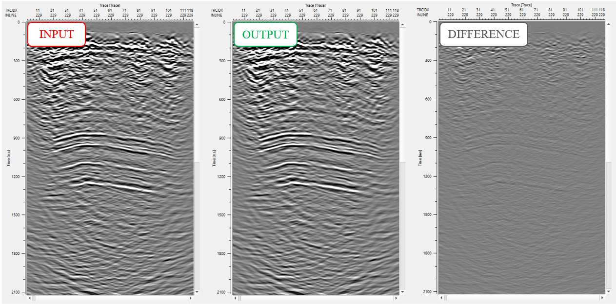
Execute the module and open input, output and difference stack windows:
--------------------------------------------------------------------------------------------------------------------------
Notice! You can flatten horizon and apply denoise procedure for better dip preserving, as well as
cut seismic trace into several parts (0-1000 ms, 1000-2000 ms, 2000-3000 ms) and apply different
procedures for particular time windows or bandwidth, and then merge them back.
--------------------------------------------------------------------------------------------------------------------------
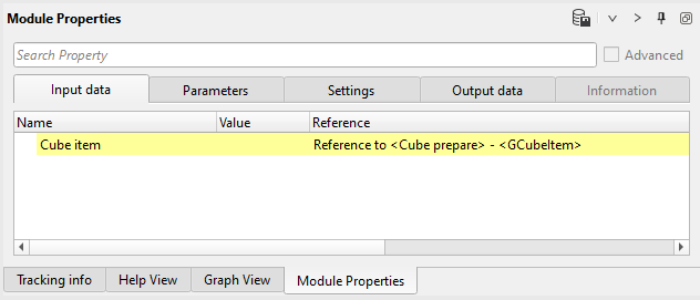
2) Cube prepare. We use this module just for creating a cube format for the FXY-Decon filter. There is no special parameters.
Input data:
Parameters:
3) FXY-Decon filter. FXY Deconvolution filter for 3D data set. This filter is designed to attenuate random noise by prediction of the non-random signal content in a seismic trace.
Apply the FX Deconvolution Filter (FXY in case of 3D) prior to minimum or zero phase deconvolution to get the better results. This should give a cleaner operator design leaving the output less contaminated by random noise.
Each input trace is transformed into the frequency domain. Groups of traces are used to design filters to predict the Fourier components of adjacent traces. The number of traces used to design the filter.
Provide number of traces (Horizontal sliding window) from T-X domain to frequency domain. Now in the frequency domain, for each frequency (Frequency range Minimum and Maximum) we generate a complex Weiner Filter to predict the amplitude and phase of the next trace. Likewise we predict the amplitude and phase for the next adjacent traces and so on. This process is carried out in forward and reverse direction and the output sample for this frequency is the average of the forward and reverse predictions. Finally predicted traces are reconstructed in the frequency domain and then transformed back into the time domain.
Input data:
Parameters:
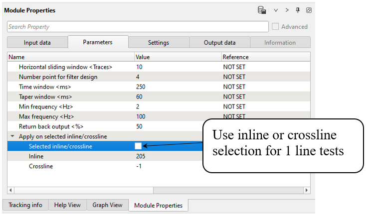
Parameters definition:
Horizontal sliding window
Number of traces transformed from T-X domain to F-X domain;
Number point for filter design
Number of traces for the Weiner Filter Design;
Time window
Time window for calculation;
Taper window
Taper area between the time windows;
Min frequency
Minimum frequency for noise attenuation;
Max frequency
Maximum frequency for noise attenuation;
Return back output
Percent of returned amplitudes after noise attenuation;
Apply on selected inline/crossline
Selected inline/crossline
By default, FALSE. If checked this option then the user can select any particular inline/crossline;
Inline
Specify the desired inline to perform the FXY Deconvolution filter operation;
Crossline
Specify the desired crossline to perform the FXY Deconvolution filter operation.
Execute the module and open stack windows (input, output and difference). Pay attention on dip events, if it is damaged, try to change parameters (softer):
All post-stack denoise procedures are harsh processing, therefore you should do it according to the task, check together test results with interpretation specialist, create a few final version of a cube: soft denoise, medium and harsh. A few version may be used for different steps on the interpretation stage (horizon and fold correlation, dynamic attribute calculation, etc). The current training project has the main goal to give knowledge to a new users: how to use g-Platform, but not getting parameters for production projects.
Obviously, that current processing sequence is not optimal, i.e. the main goal is to show how to use software for new users. Experienced geophysicist is able to create complex workflows like find the best denoise workflows, migration parameters, post stack processing and so on. You can download the final cube of some of production processing that is free and try to make better result (http://s3.amazonaws.com/open.source.geoscience/open_data/teapot/rmotc.tar).
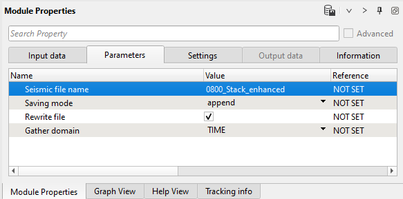
5) Save seismic by gather. Write a name for the output data set 0800_Stack_enhanced and execute the module.
Parameters:
 If you have any questions, please send an e-mail to: support@geomage.com