 | FOOT PRINTS ATTENUATION |
|
<< Click to Display Table of Contents >> Navigation: Tutorials > Seismic Processing 3D LAND >
|
Footprints are most commonly observed in the 3D seismic volumes. There are various reason for the footprints in the data set. Footprints can be produced either by acquisition or during the seismic data processing. But majority of the footprints are related to Acquisition rather seismic processing. Presence of footprints on the time slices/depth slices or on the stack section masks the resolution that leads to poor interpretation.
So what causes this acquisition footprints?
There are 3 factors which need to be considered during the acquisition survey design. Offset, Fold and Azimuth. Based on the designing of the survey fold is already preset and we can achieve the desired fold but we don’t have control on the Offset and Azimuth since we have logistical issues in the acquisition especially in the onshore. There might be a canal or a village where we can’t lay our receiver spread which creates a void and we miss the Offset and Azimuth information here. The distribution of Offset and Azimuth can be uniform within the bins or it can be vary from one bin to another. It may be uniform in inline direction but not the same case in cross line direction. This results in footprints visible on the time/depth slices. The linear spatial gird pattern seen on the 3D seismic slices are nothing but footprints. In case of the marine data acquisition it might be due to the cable feathering. The other factor which we mentioned due to the seismic data processing but the chances of generating acquisition footprints by means of processing is very minimal. During the acquisition, if we acquired the data in sparse grid we may create some artifacts during the processing. In another scenario if we have a coarse grid then we have the problem of aliasing created by steeply dipping noise events which eventually results in footprints pattern.
In this case, we are going to use de-footpints algorithm on a stack (cube), but one the best practices is to perform de-footprints on gathers: offset classes/offset cubes. By the way, in the next version of current tutorial we will update this chapter and explain how to attenuate footprints on offset classes.
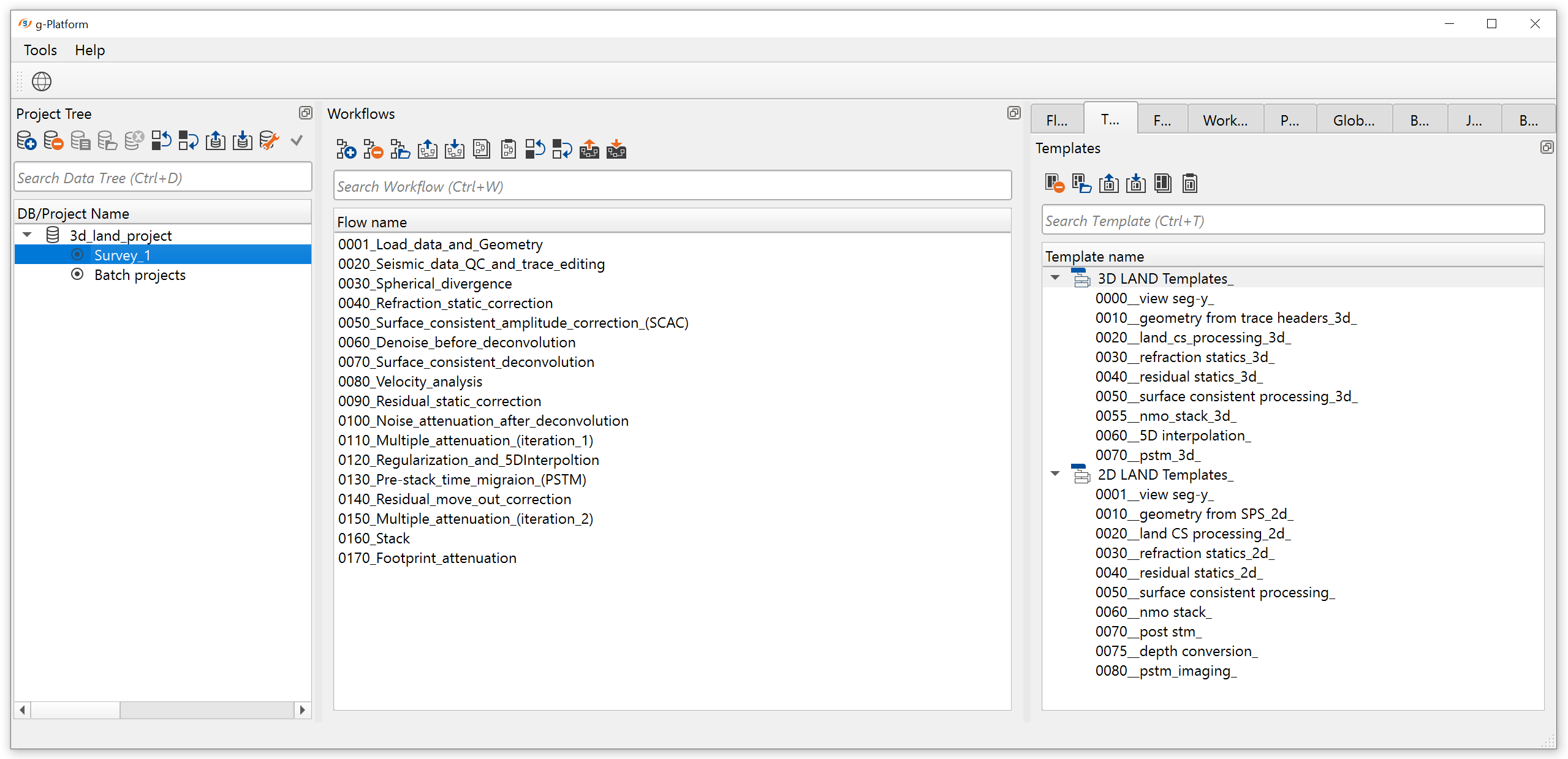
Create a new workflow 0170_Footprints_attenuation:
Add all necessary modules to the workflow:
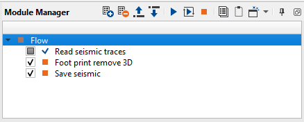
1. Read seismic traces - load seismic stack cube
2. Foot print remove 3D - system acquisition's prints attenuation
3. Save seismic by gather - save seismic stack cube
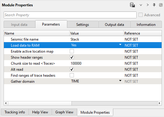
1) Read seismic traces. Load stack cube 0180_Stack data set into a RAM. We are going to use a cube pre-PSTM just for showing result without harsh migration operator's artifacts, but you can try both stack cubes for post-stack processing.
Parameters:
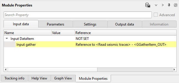
2) Footprint remove 3D. Module work in fk (Fkx-Fky) domain, reconstruct seismic data from T-X into FK domain and attenuate footprints according to user parameters. We ca use for a single stack cube or offset classes (pre-stack data).
Define input DataItems and parameters as shown below:
Input data:
Parameters:
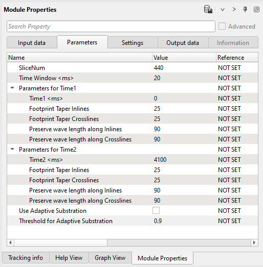
Parameters definition:
SliceNum
Time slice (ms) for tests.
Parameters for Time1
Start of the attenuation window and its parameters. Parameters are interpolated between time 1 and time 2:
Time
Time start for footprints attenuation.
Footprint Taper Inlines
Inline direction taper zone between area of attenuation and area for saving.
Footprint Taper Crosslines
Crossline direction taper zone between area of attenuation and area for saving.
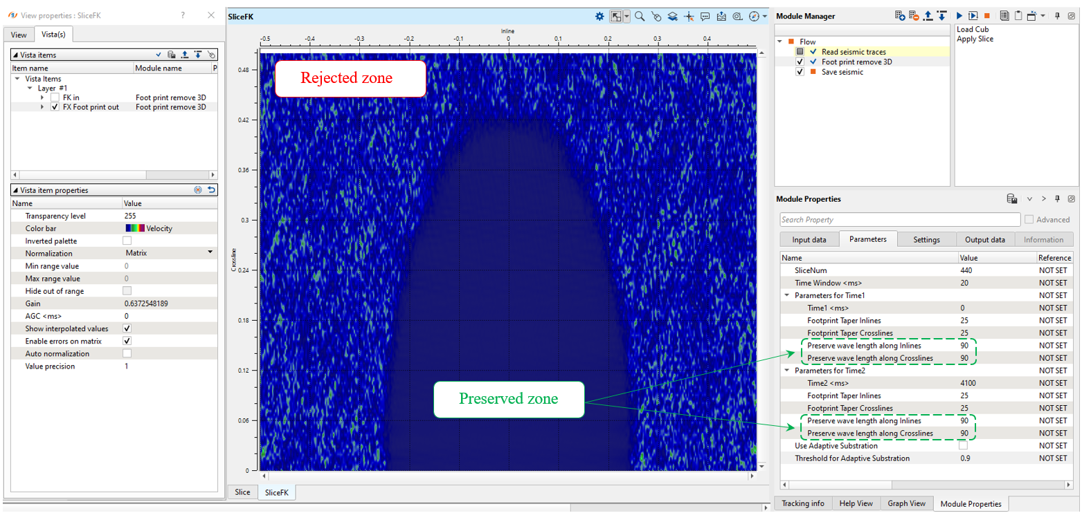
Preserve wave length along Inlines
Inline direction zone for saving area. Use FK vista windows for QC.
Preserve wave length along Crosslines
Crossline direction zone for saving area. Use FK vista windows for QC.
Parameters for Time2
End of the attenuation window and its parameters. Parameters are interpolated between time 1 and time 2:
Time
Time end for footprints attenuation.
Footprint Taper Inlines
Inline direction taper zone between area of attenuation and area for saving.
Footprint Taper Crosslines
Crossline direction taper zone between area of attenuation and area for saving.
Preserve wave length along Inlines
Inline direction zone for saving area. Use FK vista windows for QC.
Preserve wave length along Crosslines
Crossline direction zone for saving area. Use FK vista windows for QC.
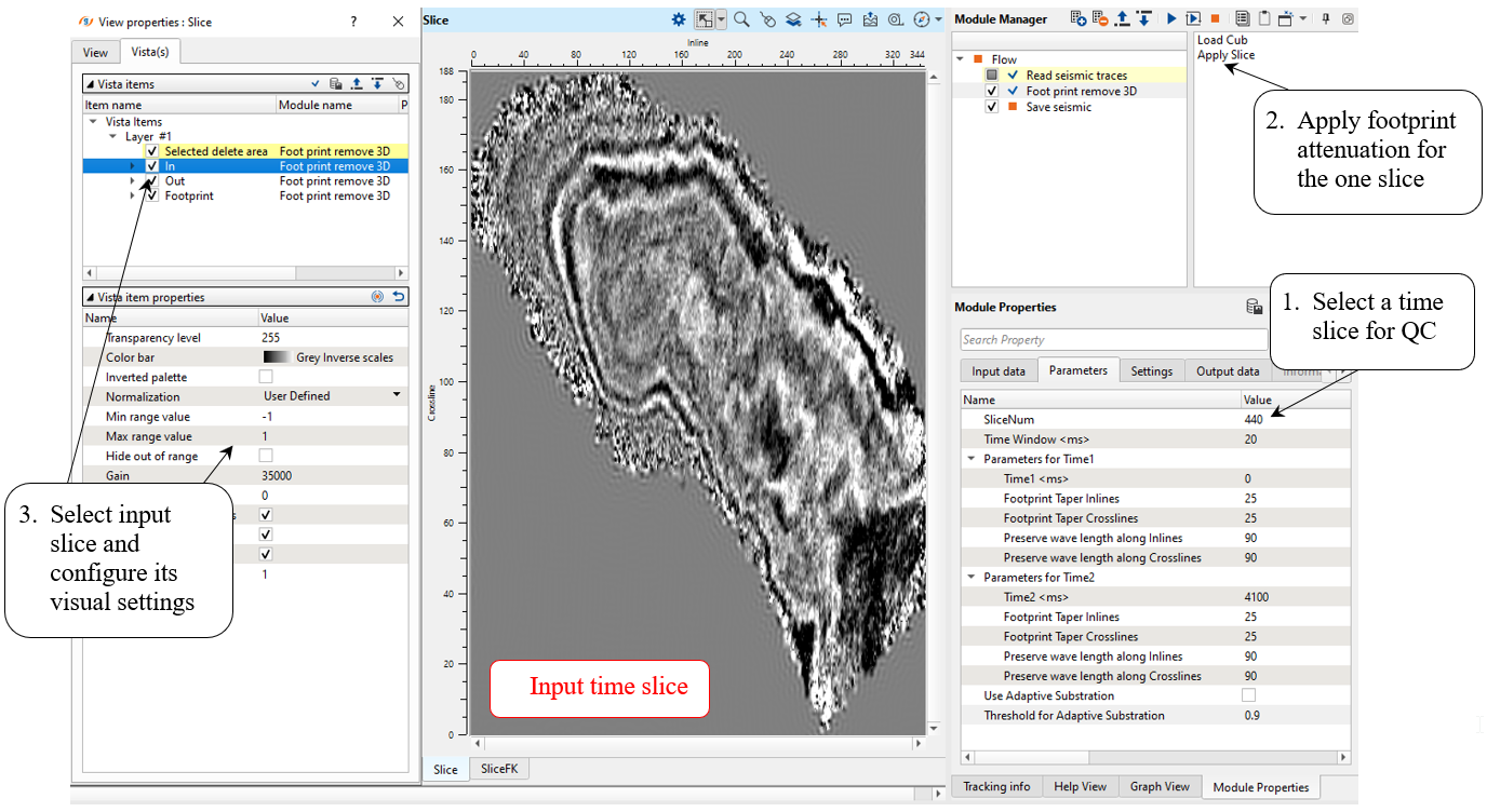
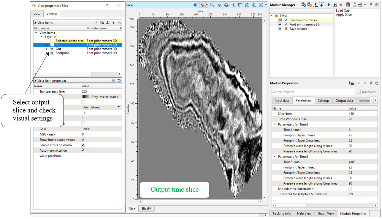
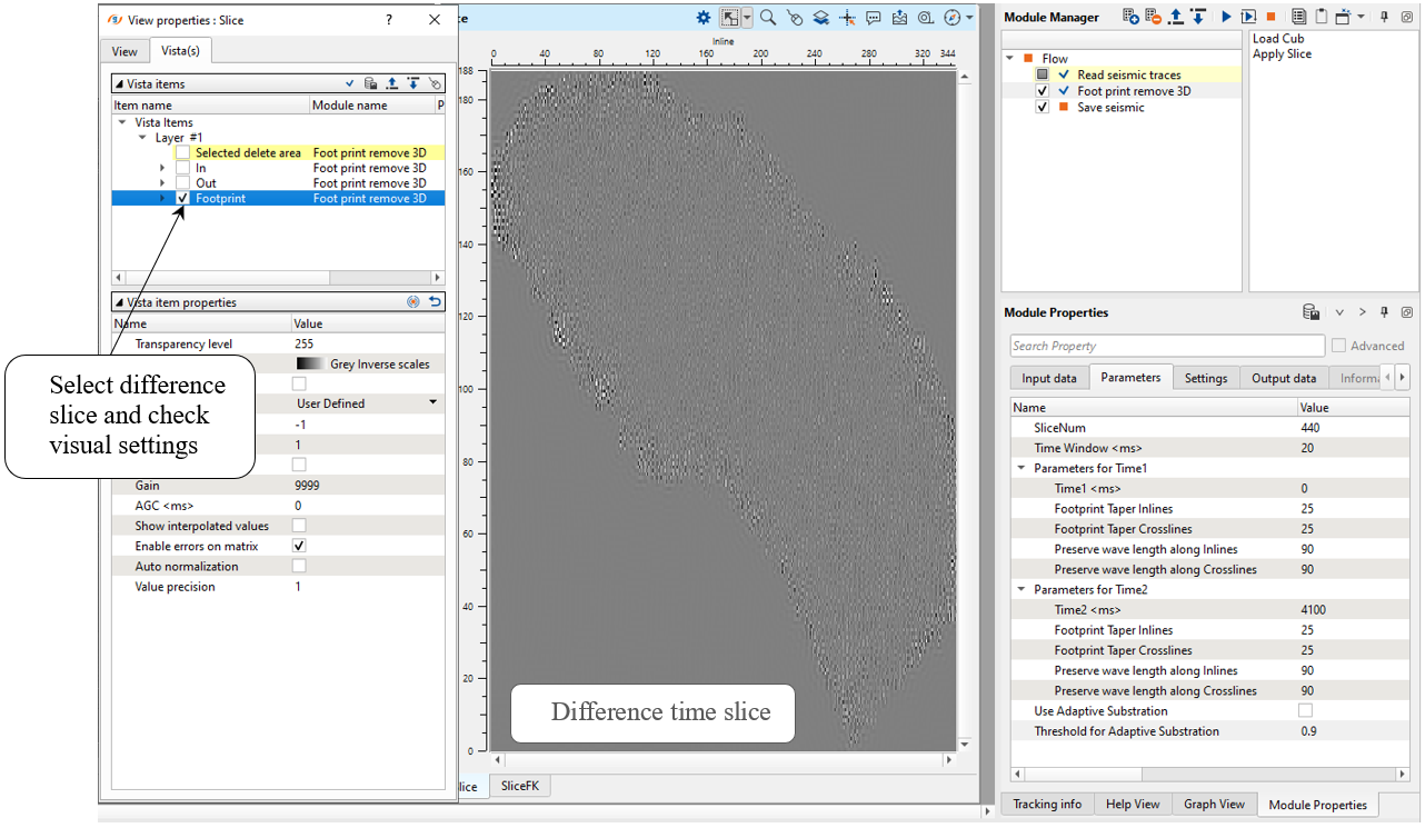
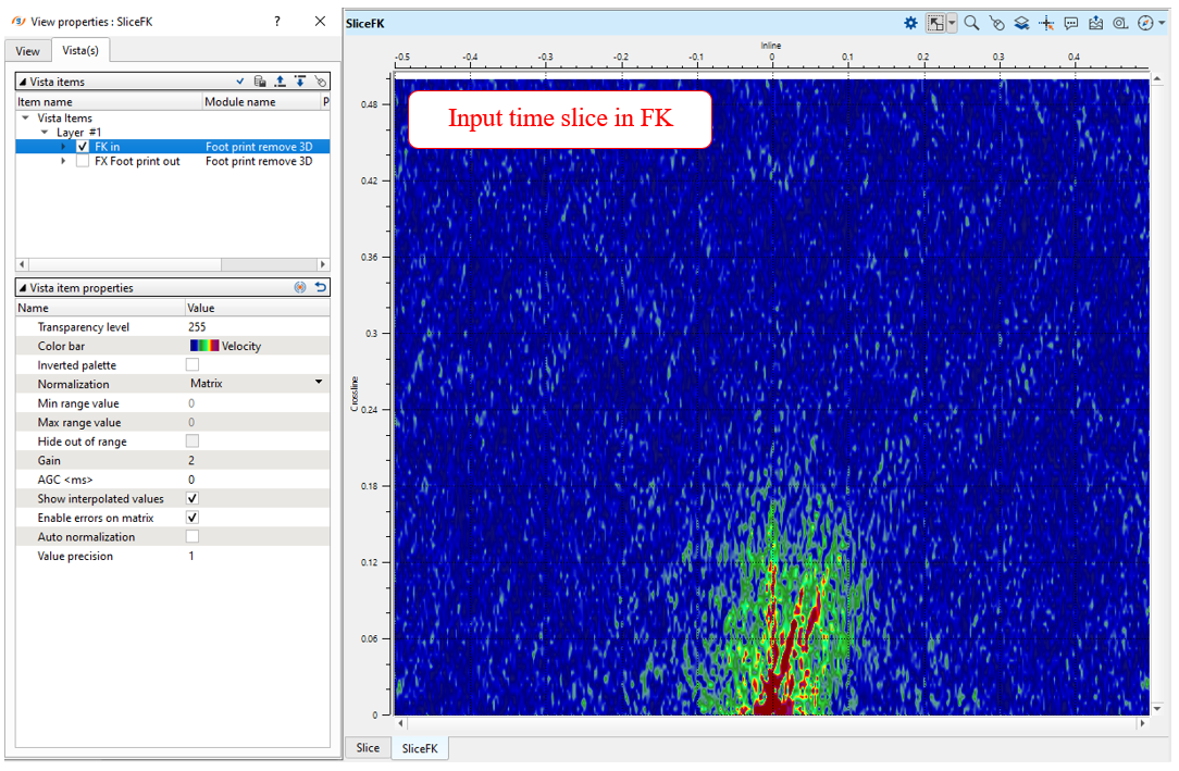
Open all vista groups and have a look at the action menu. There are 2 options: Load cube and Apply slice. The meaning is quite simple, Load cube is for loading seismic stack cube and Apply slice is for QC (footprints attenuation) before entire data execution. So, select current time slice SliceNum for tests, fro example 440 ms, press apply on Apply slice and check the result:
Check result on the FK spectrum (current time slice in FKx-FKy domain), before and after attenuation:
Execute the module and save the resulting seismic stack cube.
3) Save seismic by gather. Define an output file 0190_Defootprints name and execute the module.
 If you have any questions, please send an e-mail to: support@geomage.com