Source and receiver ghost-waves attenuation
![]()
![]()
In marine seismic data it is an usual issue of the event interference: reflection and ghosts from source and receiver sides. The reason of existing ghost waves is that source (airgun) and receiver (streamer) are towed at some depth under the water level (usually 5-10 meters). A source ghost is an upgoing wave which then is reflected from the air-water contact with changing its polarity (*-1) and then goes downward with some time delay from the primary wave. Receiver ghost is almost the same as source, but it has only another direction a downgoing wave which was reflected at the air-water contact with changing its polarity and recorded by hydrophone (Fig.1).
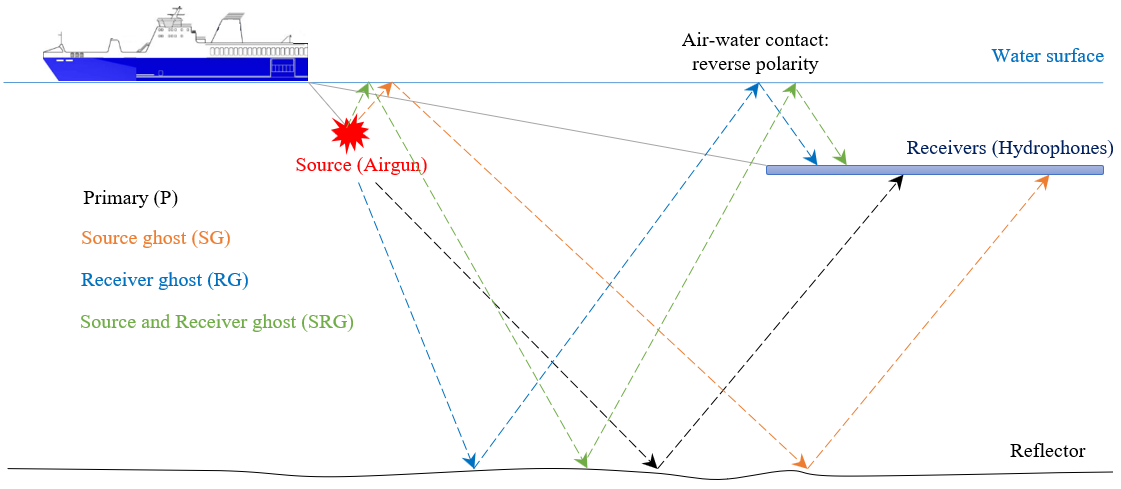
Figure 1. Ghost waves generation scheme.
Ghost waves contaminates the spectrum of conventional pressure seismic data reducing energy which is called as notches. where V is the velocity of wave in water and Depth is the source or receiver depth:
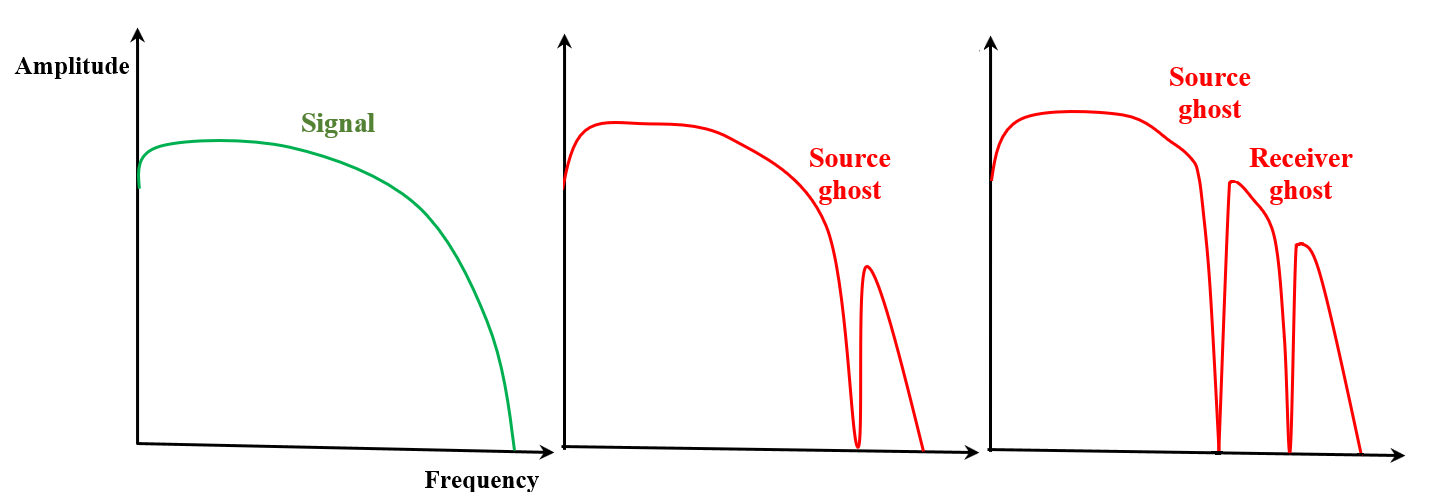
Figure 2. Amplitude frequency spectrum: primaries (left), primary+source ghost (middle) and primary+source and receiver ghost (right).
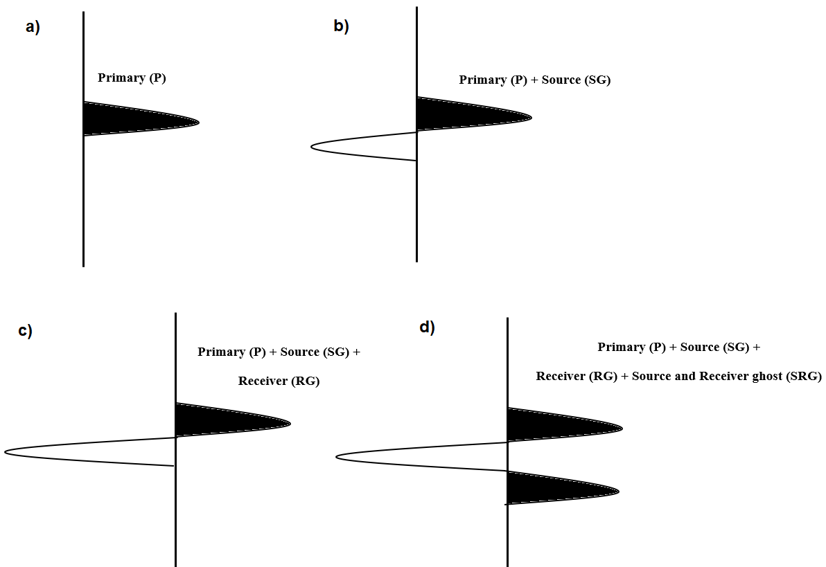
Figure 3. Wavelets: a) signal, b) signal + source side ghost, c) signal + source + receiver side ghost, d) signal + source + receiver sides ghost + source and receiver sides ghost.
Module Deghost uses f-k method to create ghost-wave model in domain and adaptively remove it from the input seismic data.
![]()
![]()
No actions
![]()
![]()
Input gather
Source gather without NMO correction. Preprocessing sequence: direct wave and swell noise attenuation, debubbling, trace interpolation and in some cases we can apply zero-phase correction before deghosting, but it must be proved.
![]()
![]()
V0 <m/s>
Velocity in the water interval (usually it is from 1470 to 1520 m/s, you should find it in the project's observer report). You can check a modeled direct wave on the Vista Window (Input) (See example below).
T0 <m/s>
Start time for processing.
Use elevation from trace headers
Read source (airgun) and receiver (streamer) depth from trace headers SOURCE_WDEPTH and RECEIVER_WDEPTH.
Source elevation <meters>
Source (airgun) depth is used for ghost modeling.
Receiver elevation <meters>
Receiver (streamer) depth is used for ghost modeling.
Use AGC
Apply auto gain control before deghosting procedure.
AGC window <ms>
Time window for auto gain control.
Use fast operator
Applying fast operator for decreasing time calculations, but less accurate result.
Padding size <traces>
Number of empty traces that will be added to the input gather for avoiding edge-effect/artefacts during FK transform process.
Taper windows <traces>
Number of seismic traces that are used for tapering between empty traces and seismic traces.
Solver params:
A task of solver is to find solution that satisfies the following condition: Input gather = gather + ghost.
Number of iterations - number of L1-norm (least absolute errors) for searching the best convergence.
Damping coefficient <%> - parameter for stabilizing a deghosting error and a solution sparsity (25 usual value), higher the value, more sparse data.
Tolerance - accuracy of difference between input gather and input + ghost.
![]()
![]()
Skip - switch-off this module (do not use in the workflow).
Auto-connection - module is connected with previous (and next) modules in the workflow by default.
Bad data values option
There are 3 options for corrupted (NaN) samples in trace:
Fix - fix corrupted samples.
Notify - notify and stop calculations.
Continue - continue calculations without fixing.
Number of threads - perform calculation in the multi-thread mode.
![]()
![]()
Output gather - input seismic data minus ghost model.
![]()
![]()
A test seismic data set is Viking Graben 2D (marine), you can download it using the following link Dataset.sgy
An example of the workflow for deghosting:
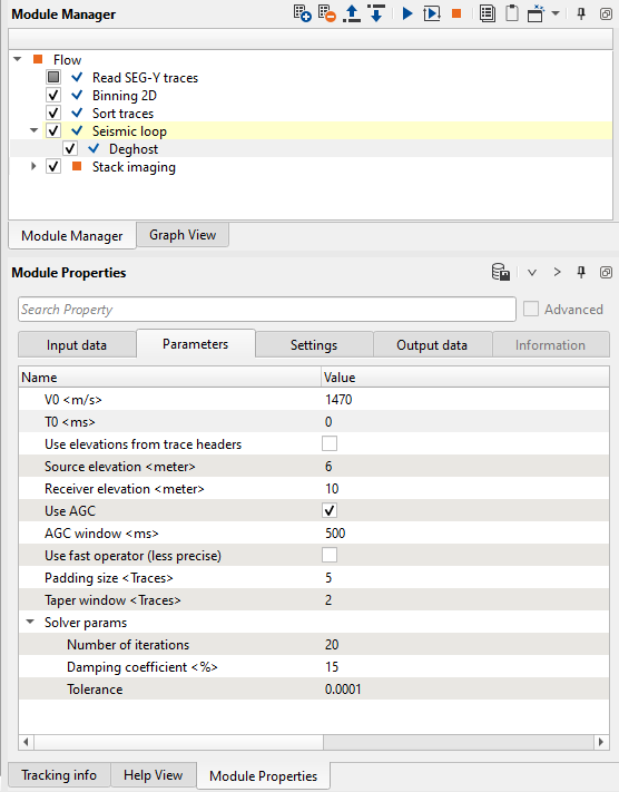
Figure 4. Workflow example with Deghost parameters.
The resulting seismic data is low frequency, due to ghosts attenuation. Therefore, it is usual prctice to apply Q-filter after deghosting procedure in order to increase amplitude of high frequencies.
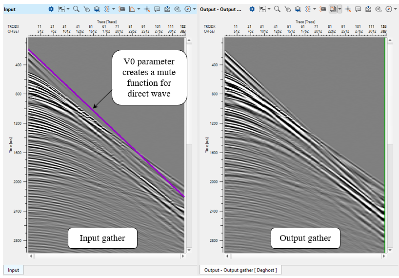
Figure 5. Source gather before (left) and after (right) deghosting procedure.
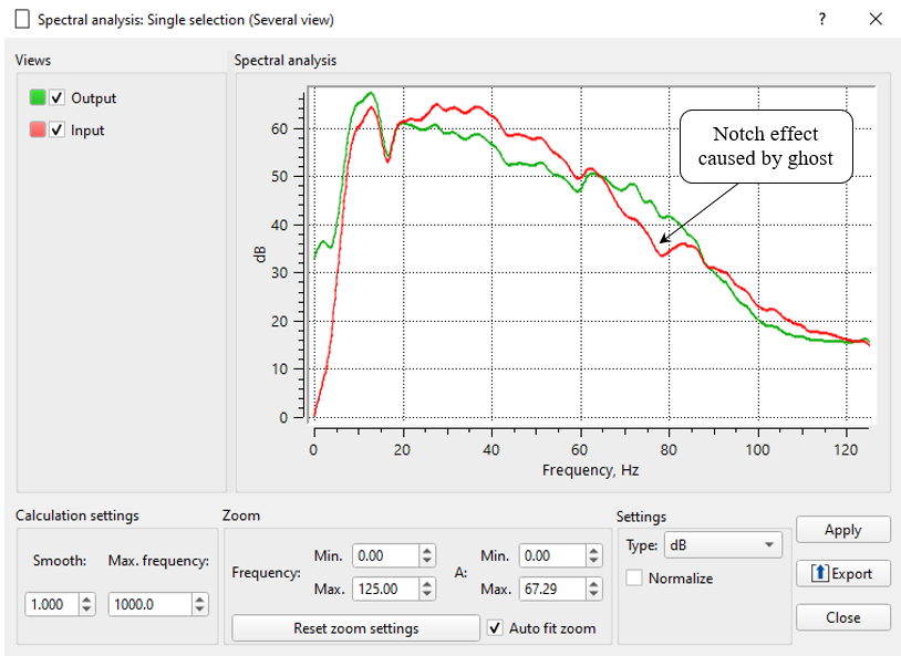
Figure 6. Amplitude frequency spectrum before (red) and after (green) deghosting procedure.
![]()
![]()
YouTube video lesson, click here to open [VIDEO IN PROCESS...]
![]()
![]()
* * * If you have any questions, please send an e-mail to: support@geomage.com * * *