 Residual random and coherent noise attenuation
Residual random and coherent noise attenuation
|
<< Click to Display Table of Contents >> Navigation: Tutorials > Seismic Processing 2D MARINE >
|
Additional denoise step performs residual noise attenuation that remained (linear, random, multiple diffraction, etc.) and appear (aliasing, artifacts, etc.) during the entire seismic processing sequence. Use this noise attenuation with caution, because it may be harsh denoise workflow, so all the parametrization and number of iteration you are able to change.
Create a new workflow 0120-Random-and-Coherent-noise-attenuation
-------------------------------Please insert the image---------------------------
Add all necessary modules to the workflow:
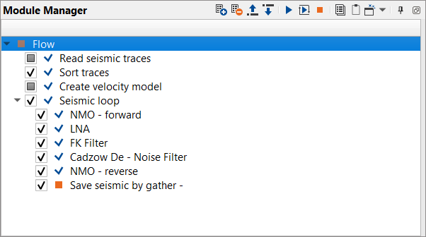
1. Read seismic traces - seismic data - load traces after de-multiples (2-nd iteration)
2. Sort traces - sort traces by CMP
3. Create velocity model - read previously picked velocities (at SRME stage) as Picks file.
4. Seismic loop - process every sorted gather in a loop (one by one)
5. NMO - apply forward NMO to flatten the gathers
6. LNA - residual linear wave and alias attenuation
7. FK Filter - residual linear wave and alias attenuation iteration in FK domain
8. Cadzow De-noise filter- residual random noise (incoherent) attenuation
9. NMO - apply reverse NMO to unflatten the gathers
10. Save seismic by gather - save gathers after denoise
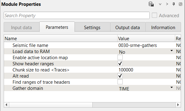
1) Read seismic traces - seismic data. Load seismic data set
Parameters:
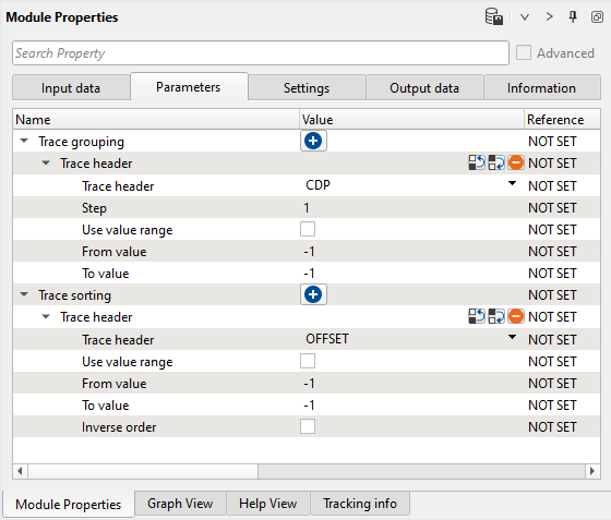
2) Sort traces. Here we need to sort seismic traces for Seismic loop. Add Sort traces module and set CDP and OFFSET header for sorting as it is shown below:
Parameters:
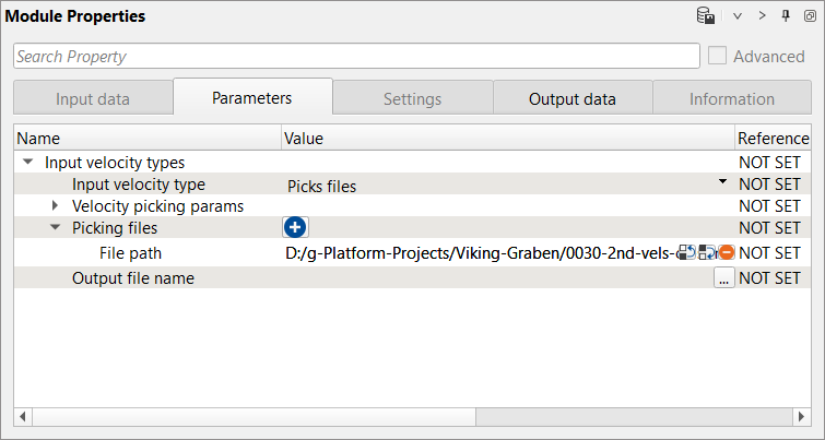
3) Create velocity model. read previously picked velocities as Picks files and create the velocity model.
Parameters:
4) Seismic loop. Connect trace headers vector (Input sorted headers) from the Sort traces module output and seismic (Input SEG-Y data handle) from Read seismic traces.
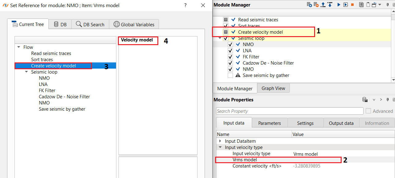
5) NMO - apply normal move out correction by using stacking velocity. Define an input data parameters: Connect/reference the Vrms model to Create Velocity model module.
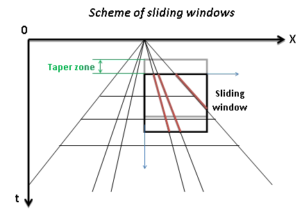
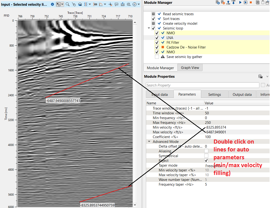
6) LNA - Linear noise attenuation. This procedure computes linear wave (noise) attenuation in the frequency-wave number (FK) domain in the local sliding time-spatial windows. Input seismic gathers transformed from the time spatial (TX) domain to the FK domain. Horizontal waves have infinite apparent velocity and shown as vertical lines in the FK domain. Vertical waves have zero apparent velocity and shown as horizontal lines in the FK domain. This definition uses for attenuate linear waves.
Zones for rejection (reject option is switch on) or saving (reject option is switch off) in the FK domain limited by velocity lines and their slopes must be defined. The slope is apparent velocity in the spatial time (T, X) domain. There is a filter of two velocities (min, max), taper’s bound defined by two mutually exclusive parameters there are frequency and slopes.
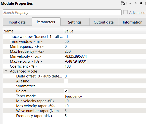
Parameters:
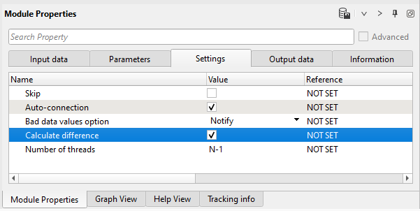
Settings:
Parameters definition:
Number of traces for sliding window. This window used for local attenuation. Taper zone between sliding windows is ¼ of trace window
•Default: -1 (all traces)
•Range: from 1 to max traces in the input gather
Milliseconds for sliding window. This window used for local attenuation. Taper zone between sliding windows is ¼ of time window
• Default: 200 (ms)
• Range: from 1 to max trace length
Minimum frequency for attenuation
•Default: 0 (Hz)
•Range: from 0 to max samplingfrequency(Hz)
Maximum frequency for attenuation;
• Default: 250 (Hz)
• Range: from 0 to max samplingfrequency (Hz)
Minimum velocity for attenuation
• Default: 100 (m/s)
• Range: from -∞ to +∞ (m/s)
Maximum velocity for attenuation
• Default: 100 (m/s)
• Range: from -∞ to +∞ (m/s)

Coefficient
Coefficient (%) for more intensive attenuation with high values, and less intensive attenuation with low values
• Default: 100%
• Range: from 0 to 100%
Distance between traces
• Default: 0 – auto detect distance
• Range: from 0 to max offset of the input seismic data (m)
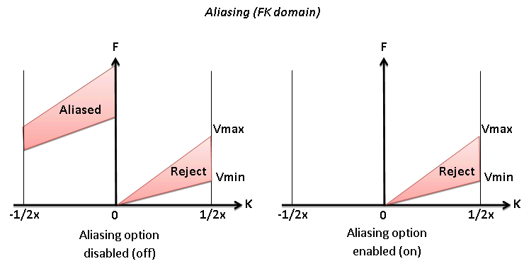
Option for exclude aliasing effect
• Default: off
• Range: on, off
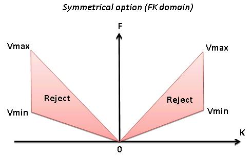
Symmetrical
Option for symmetrical attenuation (positive and negative velocity together)
• Default: on
• Range: on, off
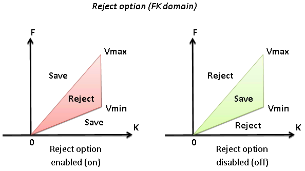
Reject
Option for reject (on) or save (off) data between Vmin and Vmax
• Default: on
• Range: on, off
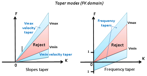
Type of taper zone between reject and save zones
Percent from minimum velocity
•Default: 10 (%)
•Range: from 0 to 100 (%)
Percent from max velocity
•Default: 10 (%)
•Range: from 0 to 100 (%)
Taper defined by frequency:
• Default: 5 (Hz)
• Range: from 0 to max samplingfrequency (Hz)
This modules does have interactive velocity range parameter definition. Open all vista groups. Go to the input gather window and activate Selected velocity lines:
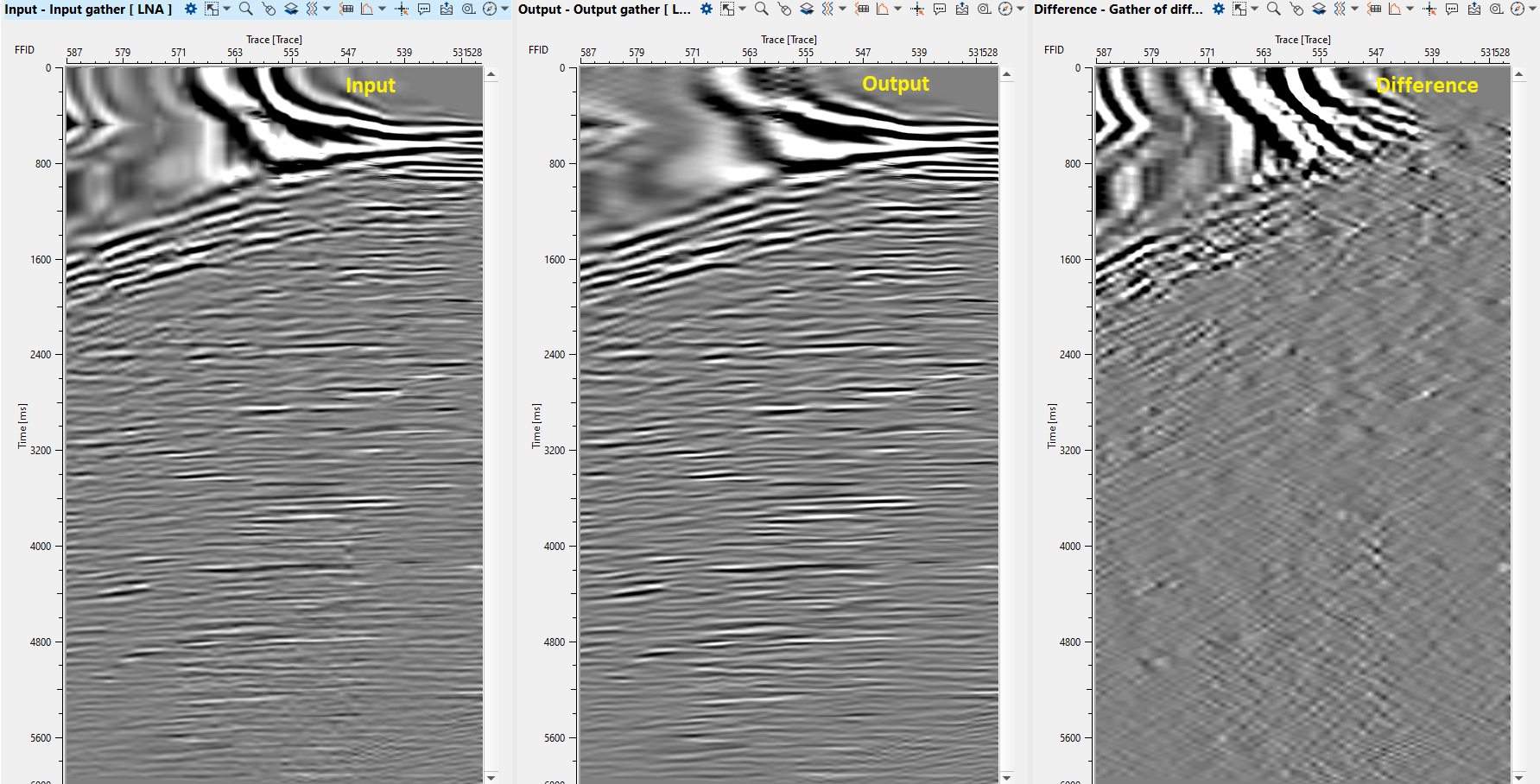
Execute the module, open vista windows and check result:
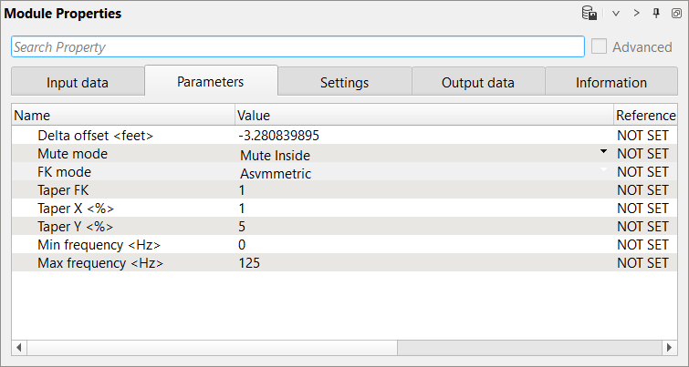
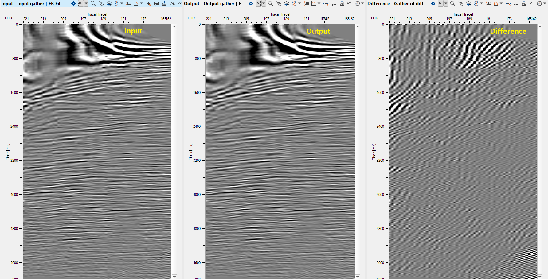
7) FK Filter - This module applies an FK filter. FK transforms 2D data to frequency-wave number space. A user can then define a mute zone in that space to apply an FK filter. Define parameters:
Parameters:
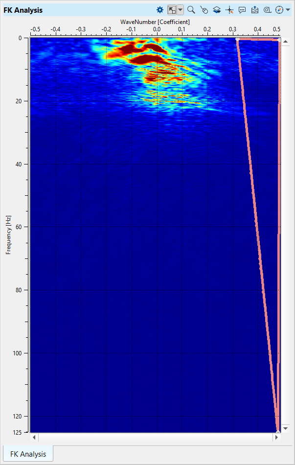
Open FK Analysis vista window and draw a polygon on the right side of the spectrum:
Execute the module and check the result:
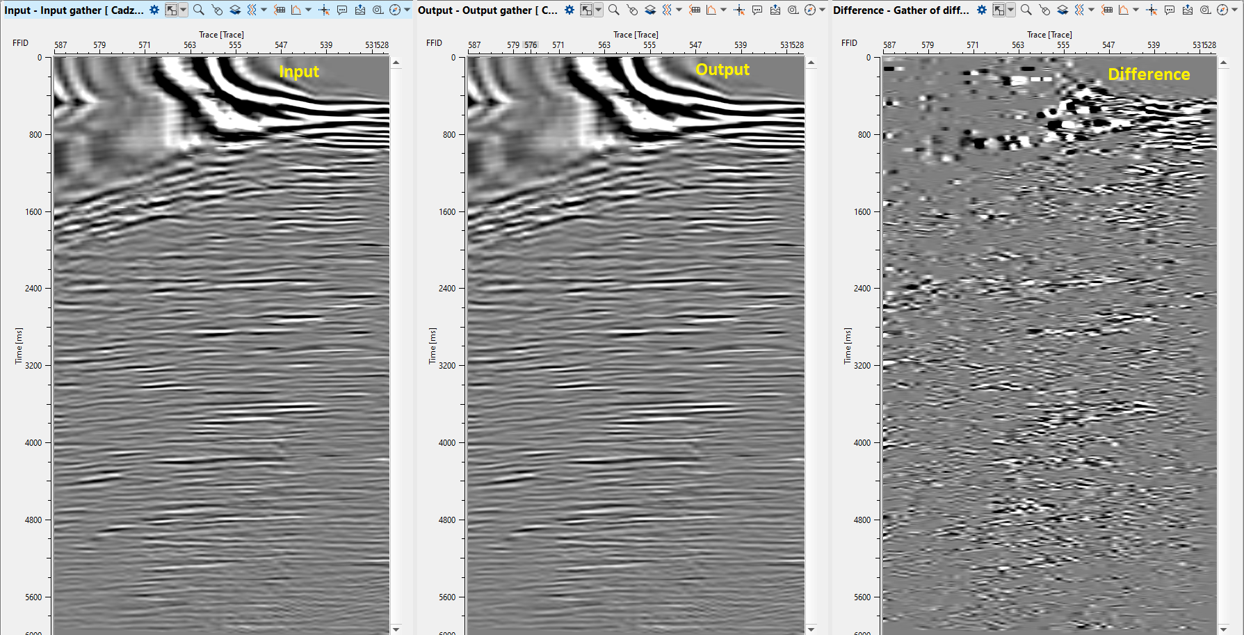
8) Cadzow De - Noise Filter. There are several modules for random denoise: RNA (Random Noise Attenuation), SVD Denoise filter, Cadzow De – Noise Filter, FX-Decon filter modules. Those filters have similar algorithms, parameters, results, but difference is in the domain which is used for seismic data transformation. Therefore, we will use Cadzow De – Noise Filter and RNA (Random Noise Attenuation). We are using Cadzow De-Noise filter for random noise attenuation. This module attenuates the incoherent noise from the seismic data that is not linearly predictable after transform a seismic data into FX-domain.
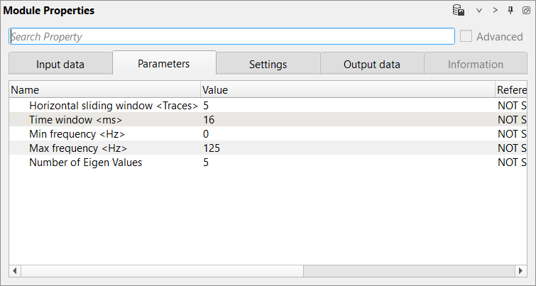
Horizontal sliding window (Traces) - Define the number of traces to be considered in the calculation of the incoherent noise attenuation. The middle trace acts as a pilot trace and calculates the noise component with the rest of the traces on both sides of this middle trace and moves to the next trace.
Time window - Define the vertical time window. This will form the spatial window along with Horizontal sliding window. Within this window, the algorithm calculates the incoherent random noise.
Minimum Frequency - Define the minimum frequency should be considered in the noise attenuation calculation
Maximum Frequency - Define the maximum frequency value
Number of Eigen values - This parameter is the key in deciding how harsh or mild to attenuate the incoherent random noise. The lower the Eigen value the harsher the noise attenuation.
9) NMO - apply reverse normal move out correction by using stacking velocity to unflatten the gathers prior to Save. Reference/connect to the input velocity model which is under Create velocity model module.
10) Save seismic by gather - Define an output file name 0130-random-and-coherent-noise-gathers. Turn off all difference calculations and execute calculations for the entire data set.
Next step >>> Velocity analysis.
 If you have any questions, please send an e-mail to: support@geomage.com