Seismic loop is an interactive procedure designed for processing data in a gather by gather mode. Using this procedure, the user can create a sequence of specific processing modules that will be contained in the Seismic loop. Processing is performed on the seismic data based on the user specified sort order output from the Sort Traces module which must precede this module in the workflow, and must provide the sorted input trace headers.
This module can also be used for quality control of input seismic data. Traces are displayed in accordance with the input sorting. Vistas that are interactively connected allow the user to step through a data volume, reviewing the results of the processing modules included in the Seismic loop processing sequence. Interactivity between the Location Map Vista and the Seismic display Vistas allow for random access to all gathers in the input seismic data.
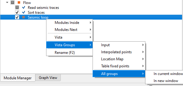
There are multiple ways to display the Vista items (location map, input gather etc.) of Seismic Loop.
•To display the Vista items of any module user should use MB3 (right mouse button) and select Vista Groups followed by All Groups. Now we have two options to choose
In current window – Vista items will be added to the View Manager however if there are any existing vista items are there then the new vista items will be added to the existing one and it is often times confusing. To avoid this user should select “In a new window” unless there are no existing Vista items
In a new Window – Vista items will be added in a separate window in View Manager with the module name as the title to identify the module and it’s vista items.
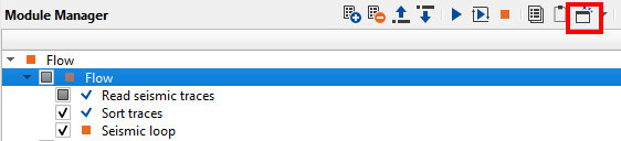
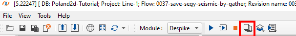
The second method is clicking on the ![]() icon ("Add module views in current window") on the top right corner of the Module Manager window as shown below.
icon ("Add module views in current window") on the top right corner of the Module Manager window as shown below.
When user add the Vista items using this method, it is very useful in Seismic Loop. When there are multiple modules existing inside the Seismic Loop module, user can interactively see the results of the individual modules by simply selecting the module and go back and forth to see the resulting output of that particular module. To replicate this user should do the following procedure.
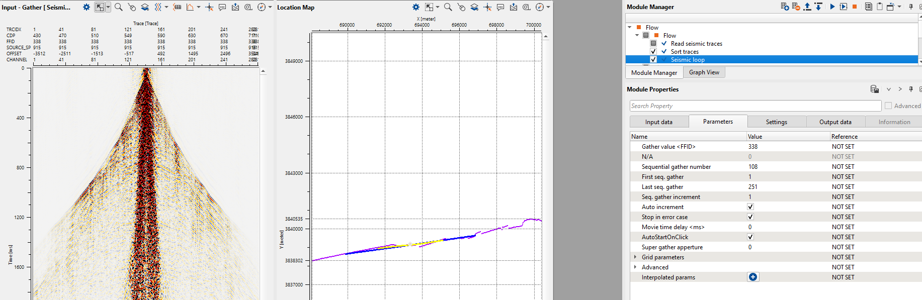
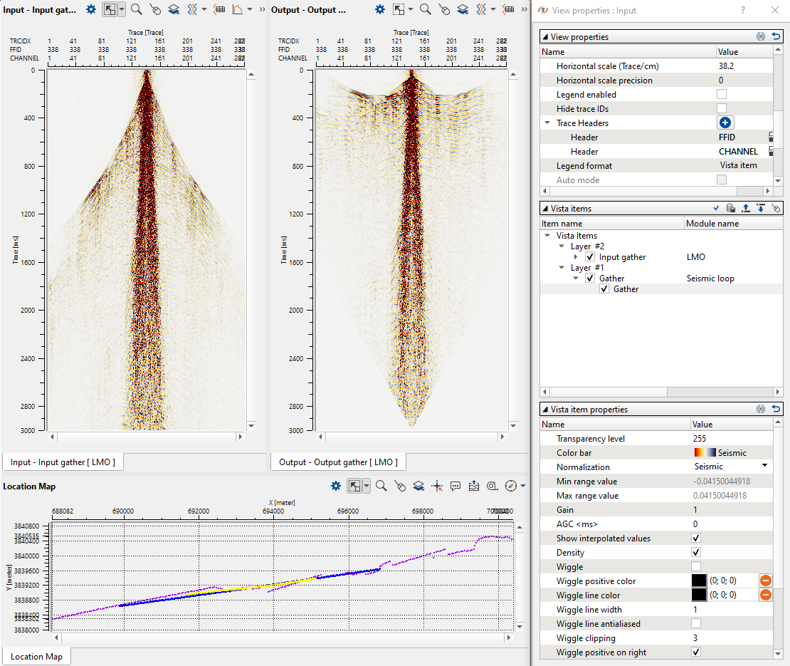
Click/select Seismic Loop module and click the Add module views icon. It will display the vista items as shown below.
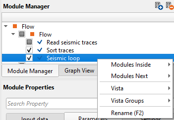
It is worth to mention that whenever user wants to add a new module after seismic loop by right mouse click on seismic loop it will give an option of Modules Inside, Modules Next besides the regular vista items etc. Modules inside option inserts the module within Seismic Loop where as Modules Next option inserts the module outside the Seismic Loop.
Now user added a new module LMO by using Modules inside option and it will be added under Seismic loop module. To display the vista items, we should click the icon “Add module views” instead of MB3 or right mouse button click to see the interactivity of the tool.
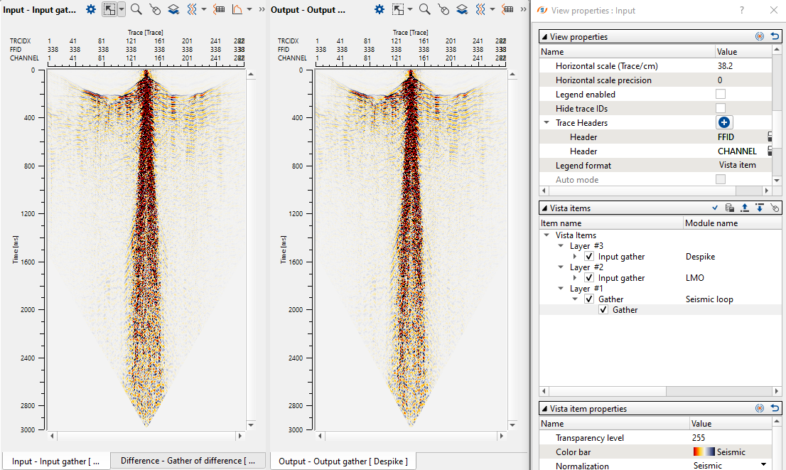
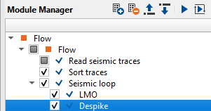
Now let’s add another module, Despike and follow the same procedure to add the vista items as we did earlier.
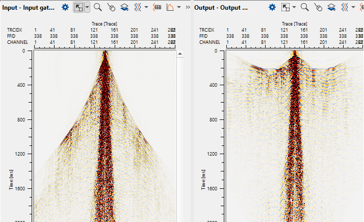
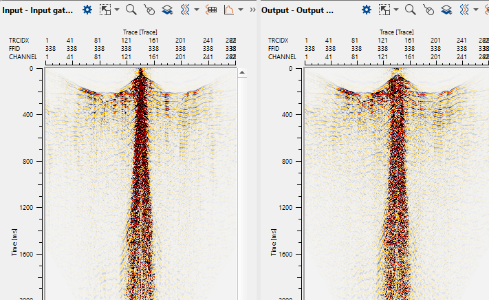
To see the animation of LMO and Despike outputs, we should select the individual modules and see the changes on the shot gathers.
In the above image, we selected LMO and it's vista items were added using the ![]() icon. Likewise we selected Despike module and added the vista items (below image) the same way. When we select LMO and Despike modules, we can see the animation of the individual modules output results.
icon. Likewise we selected Despike module and added the vista items (below image) the same way. When we select LMO and Despike modules, we can see the animation of the individual modules output results.
Like this we can add many modules inside the seismic loop module . Use can randomly and interactively select the shot/receiver/bin locations on the location map and test the parameters to see the results instantly.
The third method to display the Vista items of any module is as described below. To display the vista items, user should select that particular module and then click on the icon
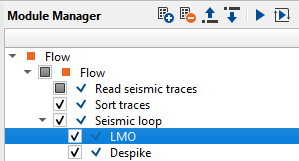
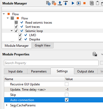
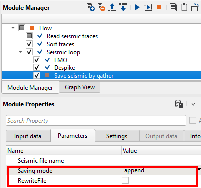
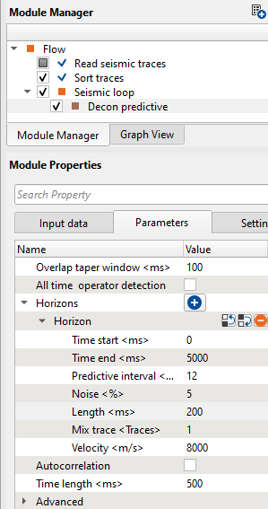
There are couple of other important features within the Seismic Loop module. If user adds any modules within the seismic loop, they need not to make the references since the reference connections are automatic process. As you see on the Settings tab, Auto-connection option is checked. In the above example, Input to the seismic loop is from the read seismic traces module, this will act as an input to the LMO module. After the LMO operation, output gather of LMO will act as an Input to the Despike module. Likewise output of Depsike will be Input to the next module. User should remember that, to save the output within the seismic loop, they must use the “Save seismic by gather module” only.
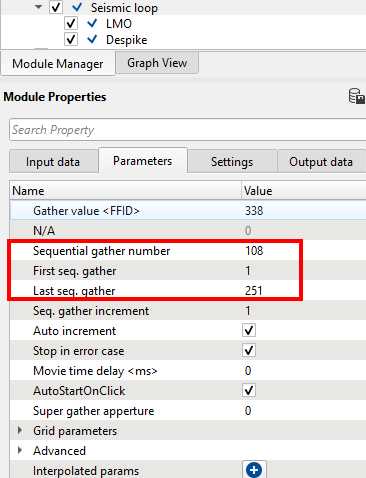
Sceario : What if the job stopped due to some reason? Do we need to rerun the entire line?
You don’t have to. In the Seismic Loop Parameters tab, we can see the First seq. gather and Last seq. gather. If you know the last seq. gather numbe then we can replace the First seq. gather with that number and keeping the Last seq. gather unchanged. Now the most important task is NOT to overwrite the existing output file name. This can be done at the Save seismic by gather module where we should select the option “append” and uncheck the RewriteFile option. So the process will continue from the new seq range and append to the existing gather of output file name.
To explain in simple way, in the current gather we have sequences 1 to 251 and we submitted the job. Due to some reason our job didn’t finish. In the seismic loop parameters tab, we can see the Sequential gather number of the last sequence where the job failed. In this case we have 108. Now we replace the First seq. gather with 109 and keep the Last seq. gather 251 as it is.
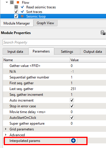
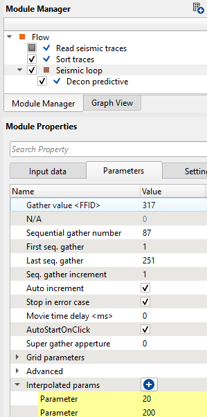
There is another important option available in Seismic Loop i.e. Interpolated params. As shown in the image we can see the Interpolated params at eh bottom of the Parameters tab. Whenever user wants to apply specific process like band pass filter/deconvolution etc to a particular FFID/Shot/CMP range then they can use this option to interpolate the respective parameters. Let us explain how it works.
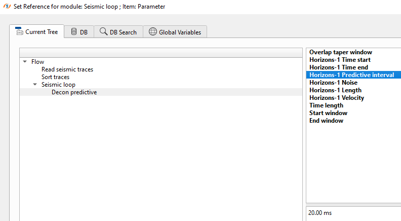
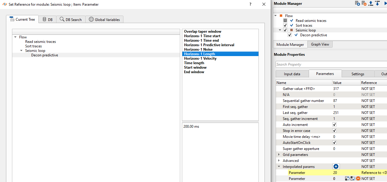
Within the seismic loop, let’s say user wants to apply deconvolution only to certain part of the line. In this case, they have to select the starting and ending points of the line and accordingly provide the parameters as shown below. To select these points, user should add vista items of the seismic loop. In addition to that we need to add an additional vista item i.e. Table Fixed points. Initially it will be blank and nothing visible. As the user added the Decon predictive module inside the seismic loop and go to Seismic loop parameters tab and click on the ![]() button. It will add a row named “Parameter”. Here user has to select the first location on the location map. Now double click on Parameter of Interpolated params and it will open the reference window and assign the appropriate item. In this case, we selected the as parameter.
button. It will add a row named “Parameter”. Here user has to select the first location on the location map. Now double click on Parameter of Interpolated params and it will open the reference window and assign the appropriate item. In this case, we selected the as parameter.
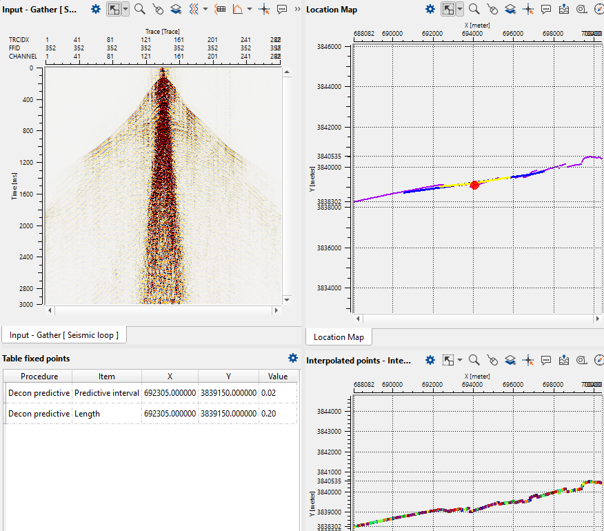
Once we click OK, then it will make the reference connection and display the first interpolation point on the Table Fixed Points as shown below.
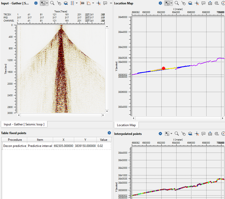
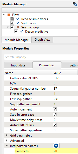
Now we can see that the interpolated points map is displaying the interpolation points on the middle of the image. On the location map where we select a point (red dot). On the far left hand side down, we have the Fixed points table where it added the information like procedure, item (predictive interval), x, y and value fields. Likewise, we have to add predictive length also. For that, we have to click the + button again on the Interpolated params and add another Parameter row to the existing one.
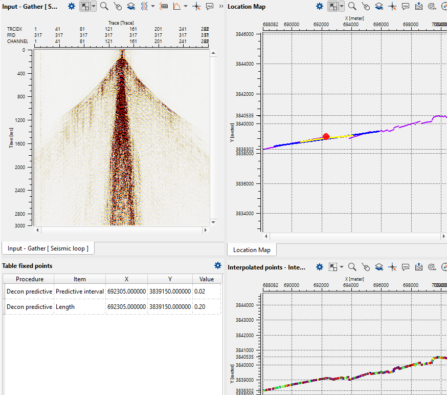
After this, we've to choose the other location point to do the interpolation between these two selected points as shown below.
To do the interpolation, we need to change the Decon predictive parameters to new values at this new location.
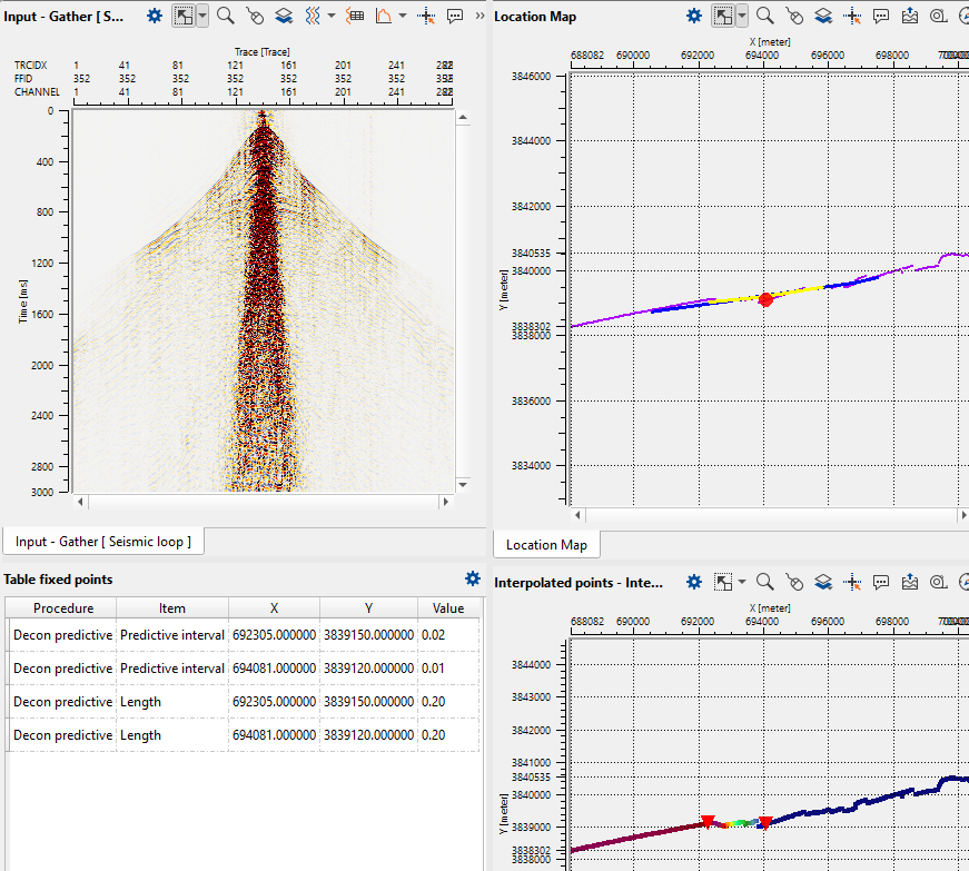
If we observe the above interpolation map, it will interpolate the Predictive interval values of 20 & 12 between these two triangles only. This way we can to interpolate any parameters using Seismic Loop.