Statics calculation that based on the refractions methods requires first breaks as mandatory input data set. Therefore, we need to do a picking of the first arrivals (guide-wave) on the input seismic traces. For this task g-Platform has Refraction FB picking - azimuthal solver guide / phase / aperture module.
For the training data in this guide, we use a vibroseis seismic acquisition Poland 2D line that is accessible on the internet free or it is also included to the g-Platform installation (C:\Program Files (x86)\Geomage\gPlatform\demodata\Poland_2D_Vibroseis_LINE_01).
Tomography procedure requires high quality picks, so we are going to create accurate manual picking on the 2D line. The seismic is vibro data and it is another obstacle of using auto picking method as well as trying to use tomography procedure, the result may be far from being sufficiently addressed in comparison with the conventional reciprocal method static solution. Let’s create a workflow which will be consist of all necessary modules for tomography static calculations:
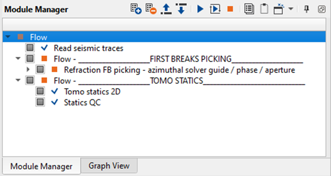
Fig. 2 Workflow for static calculation with using tomography.
| The flow consists of the following modules: |
•Read seismic traces: loading seismic data for picking;
•Refraction FB picking – azimuthal solver guide / phase / aperture – manual or auto picking of the first breaks;
•Tomo statics 2D – tomography and statics calculations;
•Static QC – quality control for statics.
Click right mouse button (RMB) on the Module Manager area and find the Read seismic traces module:
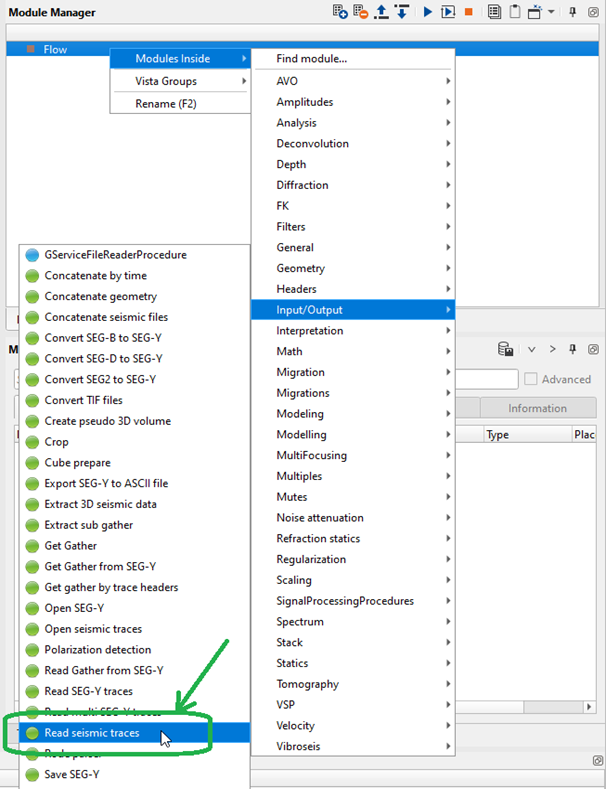
Fig. 3 Add Read seismic traces module to the workflow.
Notice that the training input data set is located in the g-Platform internal data base (DB), so you need to be sure that geometry assignment step was done properly and all necessary trace.
headers are existed in traces. Usually, input gather is a source-receiver sorted data, but sorting is not required for FB picking.
Define the Seismic file name parameter for reading seismic data from the DB by choosing a data set you have in the project. Other parameters should be as default.
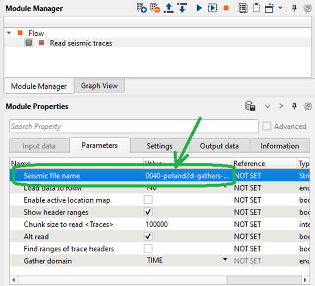
Fig. 4 Parameters of the Read seismic traces module.
Add the next module Refraction FB picking – azimuthal solver guide / phase / aperture and define its parameters as suggested in the example below:
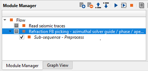
Fig. 5 Add Read seismic traces module to the workflow.
Input SEG-Y data handle and Input trace header get from the previous module. Double click on the parameter and select handle as shown on the picture 6:
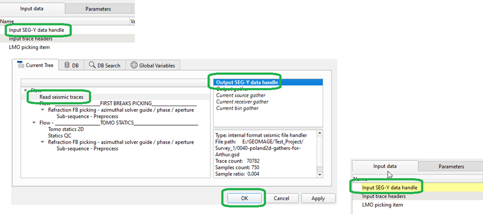
Fig. 6 Getting Input SEG-Y data handle.
In the same manner need to get trace headers:
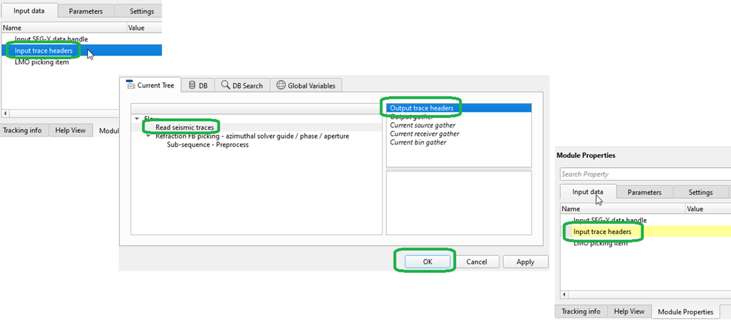
Fig. 7 Getting Input trace headers.
This module computes the static correction based on the first breaks of the data. It allows the user to interactively pick or correct the automatically picked first breaks. Subsequently, the first breaks can be used to solve for a refraction static solution generating a static correction for the source and receiver positions. The module calculates only the refraction correction, that is, replacing the near surface low velocity layers from the surface to the base of the calculated near surface. The module does not include an elevation correction, a shift to correct the data from topography to final datum. This correction to final datum is performed with a separate module “Shift Data”. Since most processes in g-Platform that would require the statics applied (for example NMO) can be run from topography, being able to easily separate the refraction correction from the final datum correction is very useful.
The module uses the picked first breaks and user provided parameters for the solver to calculate the source and receiver static correction at each surface location. The solver includes options to calculate a smoothed solution, as well as to solve into multiple azimuths. Additionally, a residual correction can be calculated and applied at each source and receiver giving a short-wave correction. The replacement velocity is calculated internally by the module. Upcoming changes will allow for the user to specify a weathering velocity as well as a replacement velocity. With these parameters specified the module will build a near surface weathering model and then use the user defined values to compute static corrections. But for now, we do not need to calculate statics correction by using this module, so please pay attention only on the first breaks picking.
Fill the module’s parameters before performing calculation and displaying the data set. For the training seismic we will use the following example, but you should do some extra tests by changing parameters for better understanding:
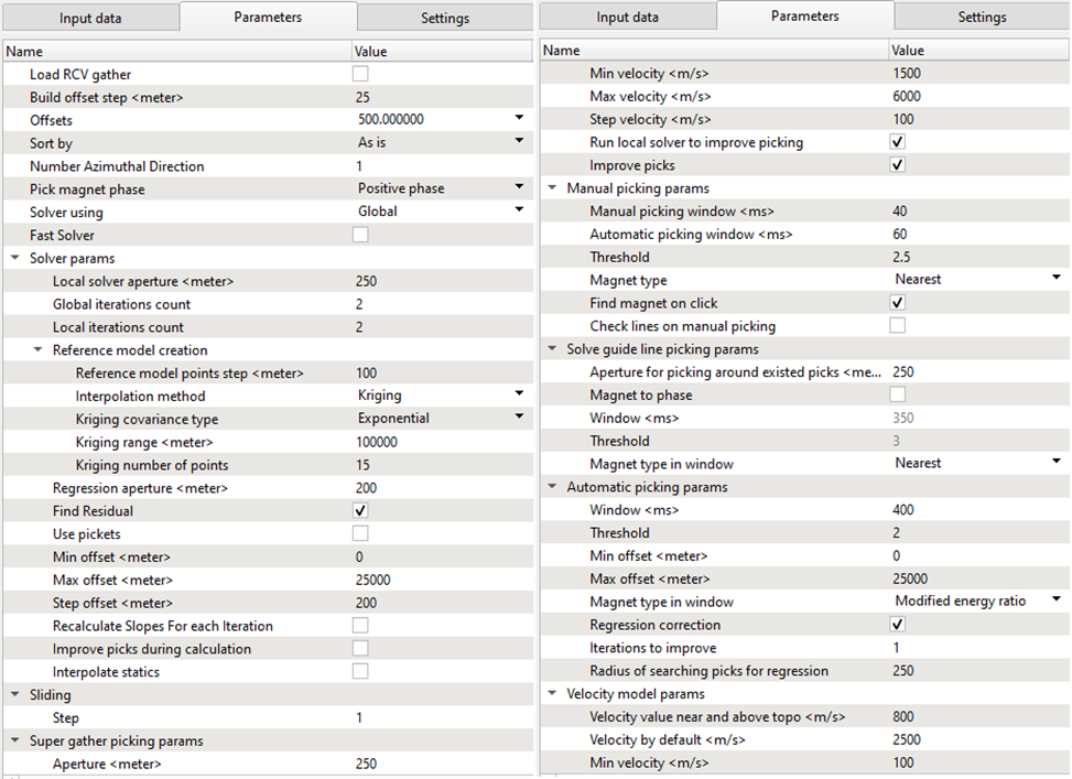
Fig. 8 FB picking parameters, part1.
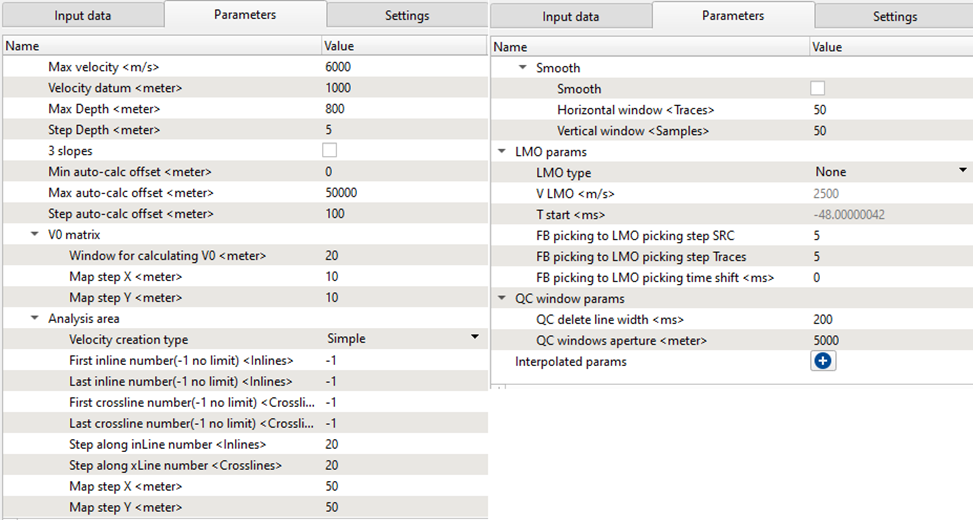
Fig. 9 FB picking parameters, part 2.
Let’s have a look at the main parameters we need for picking:
Load RCV gather
By default, it is FALSE. If checked, it will display the receiver gathers in the current receiver gather window.
Build offset step
Provide the offset step size. Depending on the offset step size, it will build the offset classes that can be chosen from the Offsets option parameter.
Offsets
Select the desired offset from the available drop down menu.
Number Azimuthal Direction
By default 1. In case of 3D, the user can define the azimuths.
Pick magnet phase
Provide the phase to pick the first breaks.
Min offset
Provide the minimum offset value for picking the first breaks.
Max offset
The user can limit the minimum and/or maximum offset values. Provide the maximum offset value for picking the first breaks.
Step offset
Offset step size. Create an offset class as a group of offsets for velocity estimation.
Sliding step
Provide the sliding value to jump to next source/receiver gather.
Super gather picking params:
Improve picks – Set picks more accurate on phase if it possible.
Aperture
Super Gather Aperture, the aperture of locations that will be picked on either side of the current pick.
Min velocity
Minimum velocity range for super gather picking.
Max velocity
Maximum velocity range for super gather picking.
Step velocity
Step velocity between minimum and maximum to be used for super gather picking.
Run local solver to improve picking
Leave checked to use the results of the local refraction statics solver to improve the results of your super gather picking.
Improve picks
Set picks to be more accurate on the phase if possible.
Manual picking params:
Manual picking window
Search window used for manual first break picks.
Automatic picking window
Search window used for in automatic super gather picking mode.
Threshold
Threshold for manual picking.
Magnet type
Phase of first breaks to be picked.
Find magnet on click
Type of energy for first breaks.
Check lines on manual picking
By default TRUE.
Solve guide line picking params:
Aperture for picking around existed picks
Provide the aperture value for picking first breaks using the solve guide line with existing picks.
Magnet to phase
Choose the phase for picking the first breaks. By default, FALSE. If checked, the next two parameters Window and Threshold will be activated.
Window
Provide the picking window.
Threshold
Define the threshold. By default 3.
Magnet type in window
By default, Nearest.
Automatic picking params
Window
Search window for automatic first break picking.
Threshold
Provide the picking threshold value for automatic picking.
Min offset
Provide the minimum offset value for first break picking.
Max offset
Provide the maximum offset value for first break picking.
Magnet type in window
There are multiple magnet types are available for first breaking picking. By default, Nearest.
Regression correction
By default, FALSE. If checked, next two parameters will be activated.
Iterations to improve
Provide the number of iterations to improve the regression correction.
Radius of searching picks for regression
Provide the search radius.
LMO params
LMO type
Type of LMO to be applied to shot and receiver gathers for picking:
None - indicates no LMO will be applied;
V const - is a constant velocity LMO as indicated by the V LMO parameter;
Picking - will apply an LMO based on the bin gather picks.


Refraction statics YouTube video lesson
Further step is setting up an user work are, it means to make an configuration of all necessary VistaWindows for QC and interactive engagement. Click RMB on the module and all VistaWindows:
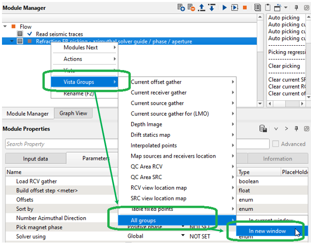
Fig. X Add Vista Groups to the work area.
The first VistaWindow we are going to use is Linear Move Out (LMO) correction on the Source gather. The LMO one of the main parameters for FB picking in view of the fact that it is used as a guide function for auto picking. Consequently, we should pick LMO guide function on a few source gathers on different locations. Picking may be exactly on the first arrivals or a little bit above them, it depends on what option (algorithm) and parameters you use for auto picking. For the training data it is enough to make LMO picking only for one source due to having a flat relief.
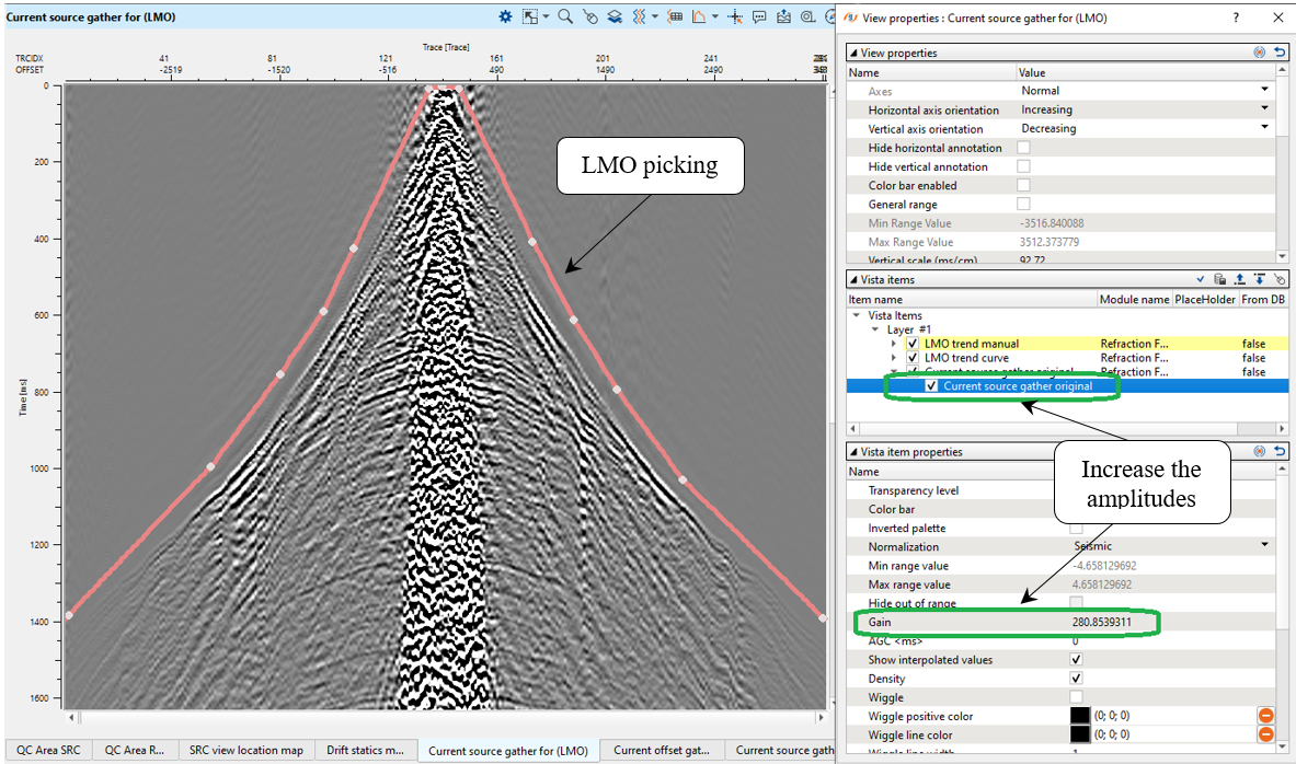
Fig. X LMO picking on the source gather.
All the visual setting were configured and we can propagate and save them:
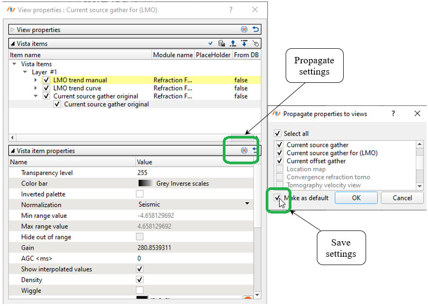
Fig. X Changing and saving view settings.
Next, open the source gather FB picking window:
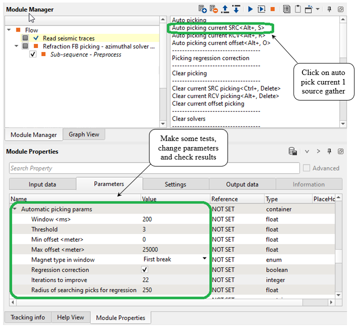
Fig. X Changing and saving view settings.
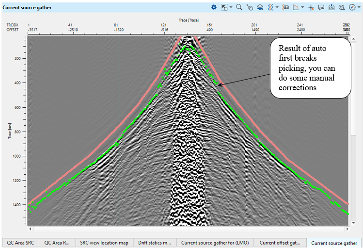
Fig. X Source gathers and auto FB picks (green).
Then we are going to launch auto picking for the entire data set by clicking on Auto picking action button:
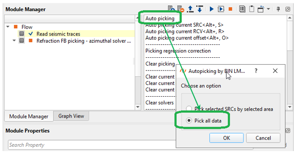
Fig. X Auto picking for the entire data set.
Check the result, it is obvious that picks became more accurate because the algorithm uses neighbor gathers for statistics:
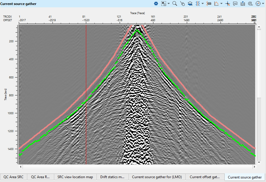
Fig. X Source gathers and auto FB picks (green), in this case auto picking was performed on the entire data set.
Eventually we have all FB picks and need to check it, open the Map sources and receiver location and activate Selected source option:
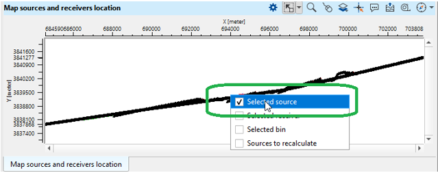
Fig. X Interactive location map.
Now we can choose any source from the location map and perform FB picks QC and editing. Other windows are connected to each other automatically, so it allows to perform interactive QC on fly:
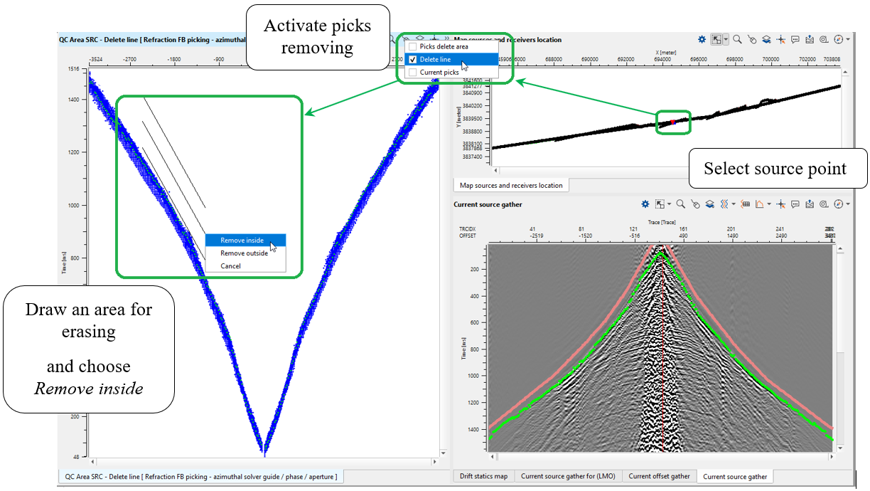
Fig. X Interactive QC and FB picks editing (delete line option) via vista windows.
Or choose another option for picks removing:
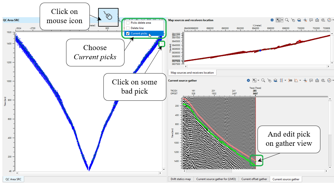
Fig. X Interactive QC and FB picks editing (current picks option via vista windows.
There are other QC windows available from the Refraction FB picking - azimuthal solver guide / phase / aperture module.
The final step is export FB picking to binary file that we will use for tomography process. Find Export picking action and choose Save in Binary, because tomo statics module requires binary format:
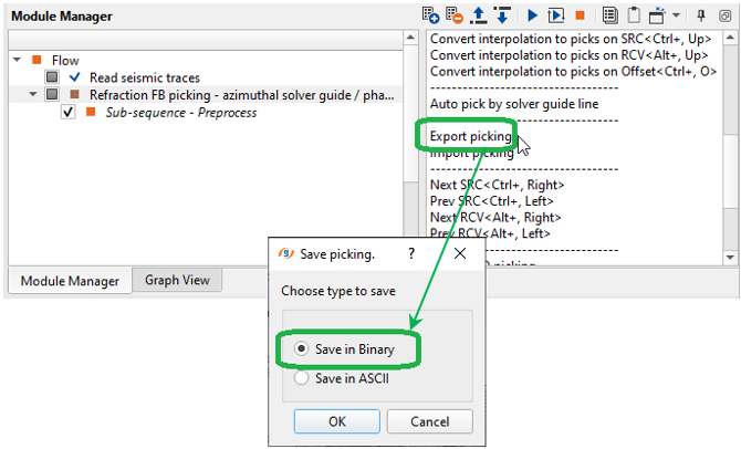
Fig. X Export FB picking into binary file.
* * * If you have any questions, please send an e-mail to: support@geomage.com * * *