Load geometry from SEG-P
Loading SEG-P1 navigation information
Theory
SEG-P1 stands for Society of Exploration Geophysicist - Portable format 1. This format stores the navigation data in text formats like ASCII which is easily readable. It takes less storage space and it can be easily compressed considering the size of the input file.
This module performs reading of navigation/survey information files in Seg-P1 format and converts them into an internal format. The converted files are used for geometry assignment.
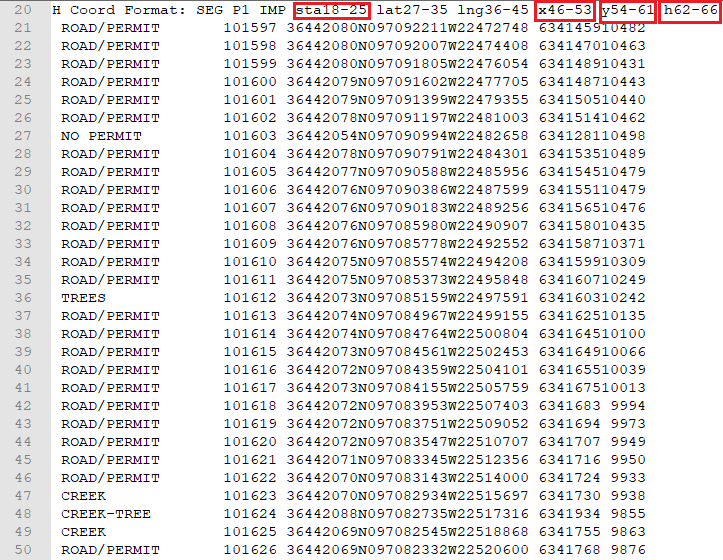
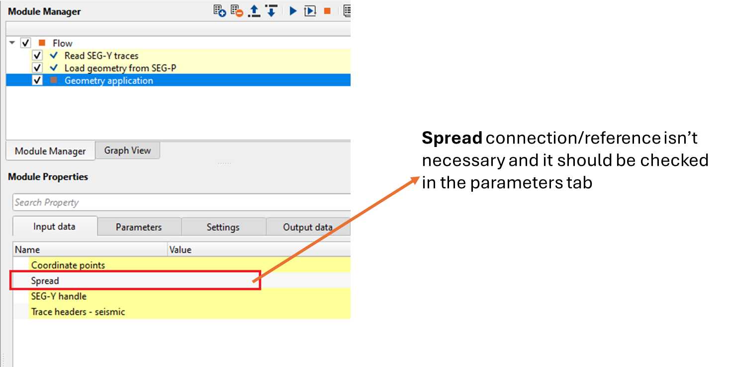
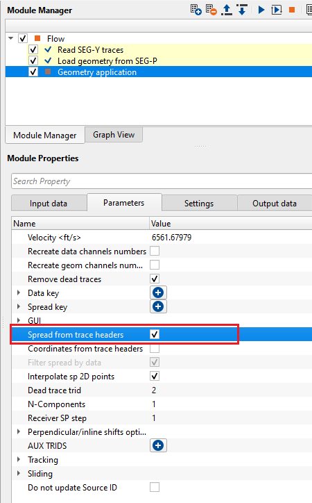
This module requires only source and receiver input files information. Unlike standard SPS format where relationship file (XPS) isn't required. The spread information is available in the trace headers of the input seismic data. In assigning Geometry, the user don't have to provide the spread information and opt for get spread information from trace headers information.
Input data
Input S-file
provide input source file path and file name. This file contains all the survey information like latitude, longitude, elevation etc. Also, in the headers, it includes all the survey information such as datum, projection, survey parameters etc.
Input R-file
provide input receiver file path and file name. This file contains all the information related to receivers like latitude, longitude, elevation etc.
Parameters
Validate geometry
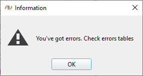
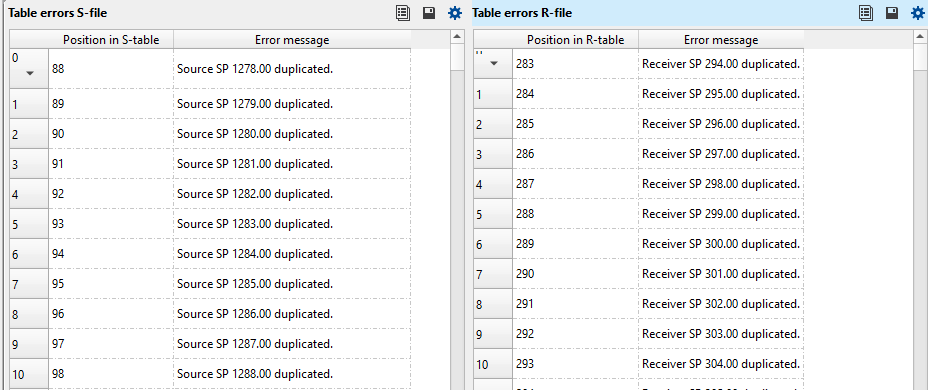
it checks if there are any duplicates existing in the input file(s). By default, TRUE (Checked). Without this option checked, it will execute the module without any error messages.
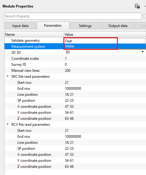
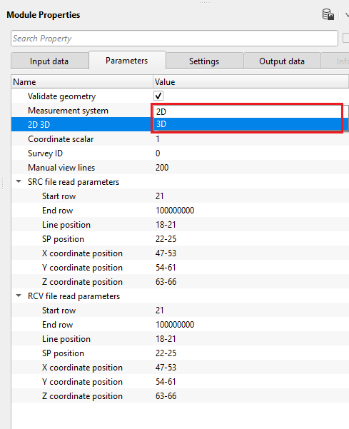
Measurement system { Feet, Meter }
select the input SEG-P1 file measurement system from the drop down menu. By default, Meter.
2D 3D { 2D, 3D }
choose the correct survey type from the drop down menu. By default, 2D.
Coordinate scalar
specify scalar value to multiply the input coordinates if required. By default, 1.
Survey ID
displays the survey ID if multiple surveys present in the input SEG-P1 file.
Manual view lines
displays first 200 rows of the input file in ManualHelperS & ManualHelperR vista items.
SRC file read parameters
this section deals with the positioning of the Source file
Start row
specify the starting row of the source file where all the latitude, longitude, station, elevation etc. information available.
End row
specify the ending row of the source file. It is not mandatory and the default value is
Line position
provide the starting and ending column position of the line
SP position
provide the Shot point start and end column position
X coordinate position
provide the x-coordinate position from the input SEG-P1 Source file
Y coordinate position
provide the y-coordinate position
Z coordinate position
provide the elevation of the source
RCV file read parameters
this section deals with the positioning of the Receivers.
Start row
specify the starting row of the receiver file
End row
by default, 100000000.
Line position
provide the start and end column positions of the line
SP position
provide the receiver point positions
X coordinate position
provide receiver x-coordinate column positions
Y coordinate position
provide receiver y-coordinate column positions
Z coordinate position
provide receiver elevation column positions
Settings
Skip
By default, FALSE(Unchecked). This option helps to bypass the module from the workflow.
Output data
Sources and receivers collection
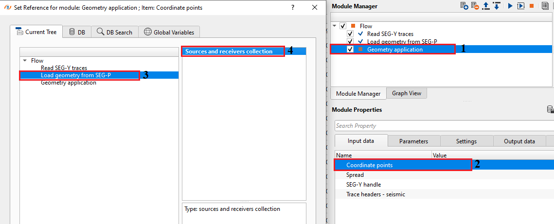
outputs source and receiver collection points which can be used as a connection/reference for the Geometry application or related module(s).
Sources geometry file table
outputs source geometry file as a table. This table can be exported as a table by using Export table module.
Receivers geometry file table
outputs receiver geometry file as a table. This table can be exported as a table by using Export table module.
Information
There is no information available for this module so the user can ignore it.
Examples
In this example workflow, we read SEG-P1 navigation data using Load geometry from SEG-P module. It requires source and receiver input files. There is no relationship file required which holds the spread information in general.
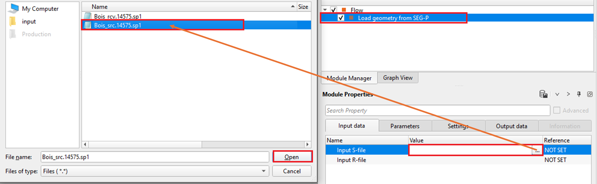
After providing both input files, go to Parameters tab and select the appropriate parameters. In this example, the measurement system is in Feet and the data is 3D. Also, adjust the source and receiver files information (row, column positions against each parameter) as per the input file(s).
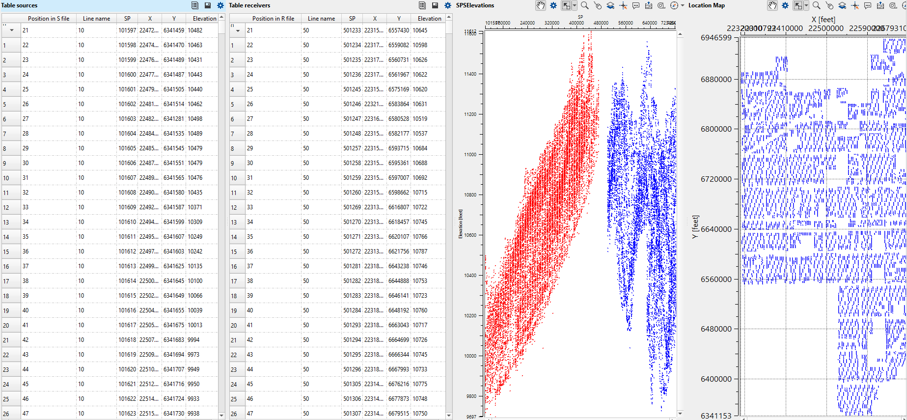
Launch Vista items and it will display all the vista items including Location map, source, receiver geometry table, elevation tables etc.
Connection/reference of Load Geometry from SEG-P module to Geometry application.
Actions
There are no action items available for this module so the user can ignore it.
Video lesson
YouTube video lesson, click here to open [VIDEO IN PROCESS...]
Related articles
Yilmaz. O., 1987, Seismic data processing: Society of Exploration Geophysicist
 * * * If you have any questions, please send an e-mail to: support@geomage.com * * *