Loading navigation data of onshore data in SPS format
![]()
![]()
For onshore seismic data, navigation data is stored in different formats like SPS, SEG-P, ASCII. SPS or Seismic Processing System is a standard format for storing the onshore navigation data. It consists of 3 main files. SPS, RPS and XPS.
SPS file deals with the source information, RPS file deals with Receiver navigation information and XPS file deals with the relationship between the sources and receivers. Primarily, two types of standard SPS formats are available. SPS 1.0 & SPS 2.1.
The module performs the reading of geometry files in SPS format and converts them into an internal format.The converted files are used for geometry assignment by using Geometry application module.
![]()
![]()
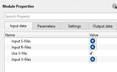
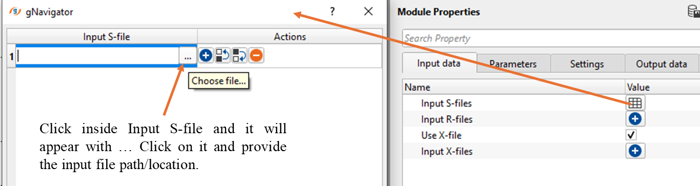
Input S-files - Provide the input Source file location. As we shown in the images, upon clicking the + icon, it will open a new window. Click inside the Input S-file and click on "...", browse through the file location and select the input file path location.
Input R-files - Provide the input receiver file location
Use X-file - TRUE, by default.
UseXFile - true - Provide the relationship (xps) file location.
Input X-files - In this case, there is no requirement of the relationship (xps) file information. It will take the information from the input trace headers if this information is already stored.
![]()
![]()
Additional offsets - If there are any additional offsets information like parallel or perpendicular offsets, define them here.
Manual description of offsets:
•FFID –FFID number
•Perpendicular offset –Perpendicular shot offset
•Inline offset –Inline shot offset
Validate geometry - This parameter checks if there any duplicate Sources and Receivers are existing in the SPS file. Also, it checks the XPS file for all SPs every line.
Measurement system { Feet, Meter } - Select the measurement system. Imperial(Feet) or Metric(Meter).
2D 3D { 2D, 3D } - Select the survey type 2D or 3D from the drop down menu.
SPS revision/preset { SPS 1.0, SPS 2.1 } - Select the SPS revision from the drop down menu.
Coordinate scalar - Multiplier for source, receiver x,y coordinates
Survey ID - Survey identification number, add manually to trace header SURVEY_ID
Receiver SP step - Define the Receiver SP step size.
N components - Define number of components if available (multicomponent)
Excluded SRC lines - To exclude any Source lines from a 3D survey, just enter the source line number(s) here by clicking on + symbol.
Excluded RCV lines - Similarly Receiver lines can be excluded from a 3D survey.
Read S file scheme - This section deals with the Source file reading scheme. If the input SPS files are as per the standard SPS format 1.0 or 2.1, these values are automatically filled as per the standard format however if the input SPS files are non-standard format then it gives the opportunity for the user to manually enter these values as per their respective positions in the input files.
Start row - Specify the starting row of the Source file.
End row - Specify the ending/last row of the source file.
Line position - Specify the sail line position of the source file.
SP position - Specify the Shot Point position from the source file.
Code position - Specify the source code position
Static shift position - Provide the statics shift position if available.
Hole depth position - Provide the Up hole depth position in the source file.
Hole Time position - Provide the Up hole time position
X coordinate position - Specify X coordinate position
Y coordinate position - Specify Y coordinate position
Z coordinate position - Specify elevation position from the input source file.
Read R file scheme - This section deals with the Receiver file reading scheme.
Start row - Specify the starting row of the receiver file.
End row - Specify the ending/last row of the receiver file.
Line position - Specify the sail line position of the receiver file.
SP position - Specify the Shot Point position from the receiver file.
Code position - Specify the receiver code position
Static shift position - Provide the static shift position if available
Hole depth position - Provide up hole depth position
Hole Time position - Provide up hole time position
X coordinate position - Specify receiver X-coordinate position
Y coordinate position - Specify receiver Y-coordinate position
Z coordinate position - Specify receiver elevation position
Read X file scheme - This section deals with the Relationship file reading scheme.
Start row - Specify the starting row position of the input XPS file.
End row - Specify the ending/last row position of the input XPS file.
FFID position - Specify the FFID position in the input XPS file.
Source line position - Specify source line position
Source SP position - Specify source shot point position
Shot index position - Specify shot index position
1-st channel position - Specify active 1st channel position
L-st channel position - Specify last channel position.
Receiver line position - Provide receiver line position.
1-st channel sp position - Provide 1st receiver shot point position.
L-st channel sp position - Provide last receiver shot point position.
Advanced -
Update elevation maps - By default, TRUE (Checked). If checked, it will update the elevation maps of both source and receivers.
Map interpolation step - Define the interpolation step size for creating the elevation map. By default, 500.
Map interpolation method { ABOS, Kriging } - Select the interpolation method from the drop down menu.
MapInterpolationMethod - ABOS - Artificial Bounded Object Structure or ABOS is a specialized interpolation method where it uses an artificial bounded structure like network of polygons to model and interpolate the elevations information to create the topography map.
MapInterpolationMethod - Kriging - It is a statistical interpolation method based on the assumption that the spatial data points are correlated. It creates an optimal surface that minimizes prediction errors by considering both the distance between data points and their spatial correlation.
Kriging covariance { Spherical, Gaussian, Exponential } - Select the covariance type from the drop down menu.
Exponential - This can be used where the subsurface properties change abruptly over small distances.
Spherical - The Spherical model is useful when the data exhibits a more gradual spatial correlation up to a certain range and then behaves independently beyond that range. When subsurface structures have coherent properties within a certain distance but lose coherence at greater distances.
Gaussian - The Gaussian model is often applied in cases where there is a long-range, gradual spatial dependence between data points. It’s suitable for data where the spatial dependence does not drop off abruptly, such as when seismic properties gradually change over larger distances or in homogenous subsurface areas.
Kriging range - If two data points are closer than the kriging range, they are considered spatially correlated and will influence each other's estimated values. If the distance is greater than the range, their influence on each other will be ignored. If the distance between two data points is more than 500 then it assumes that the data beyond that limit there is no correlation.
Kriging max points - Total number of data points used to estimate/interpolate the unknown point/sample. The more the kriging points the better result however the computation time also increase with this.
Create x,s,r tables - By default, FALSE(Unchecked). If this option is turned on, it will create the source, receiver and x tables. Please use caution when dealing with 3D datasets.
Use mapping for files - This parameters is useful when the user is reading big/large size SPS files however it requires large amount of RAM to read very large SPS files.
![]()
![]()
Number of threads - One less than total no of nodes/threads to execute a job in multi-thread mode.
Skip - By default, FALSE(Unchecked). This option helps to bypass the module from the workflow.
![]()
![]()
Sources and receivers collection - This generates the sources and receiver collection information which is further used in modules like Geometry application.
Spread - This module outputs Spread information.
Trace headers - Generates the updated trace headers information.
Sources geometry file table - Outputs source geometry file table for later usage.
Receivers geometry file table - Outputs receiver geometry file table for later usage.
Spread table - Outputs Spread table
Number of sources - Total number of sources in the SPS file
Number of receivers - Total number of receivers in the RPS file
Number of x-connections - Total number of relationship files in the XPS file.
![]()
![]()
In this example workflow, we are reading navigation file of Poland 2D data in SPS format. We've added "Load geometry from SPS" module and provided the input SPS,RPS and XPS files.
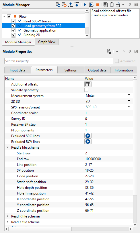
In the above image, all the source file information is automatically filled depending on the input SPS format type. In case, the user wants to change these positions then can do so by simply entering the values manually or by using the vista items. Let's see how we can edit these values using Vista items.
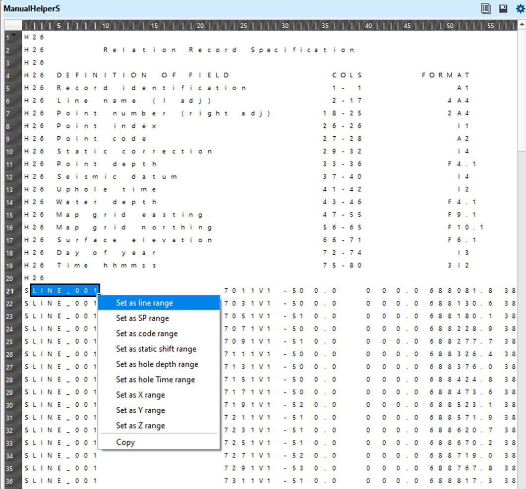
Execute the Load geometry from SPS module and generate the Vista items. There are many vista items available, however we look into the "Manual helper S" window. This window displays the headers information such as the positioning of the source line, source index, source x,y coordinates etc.
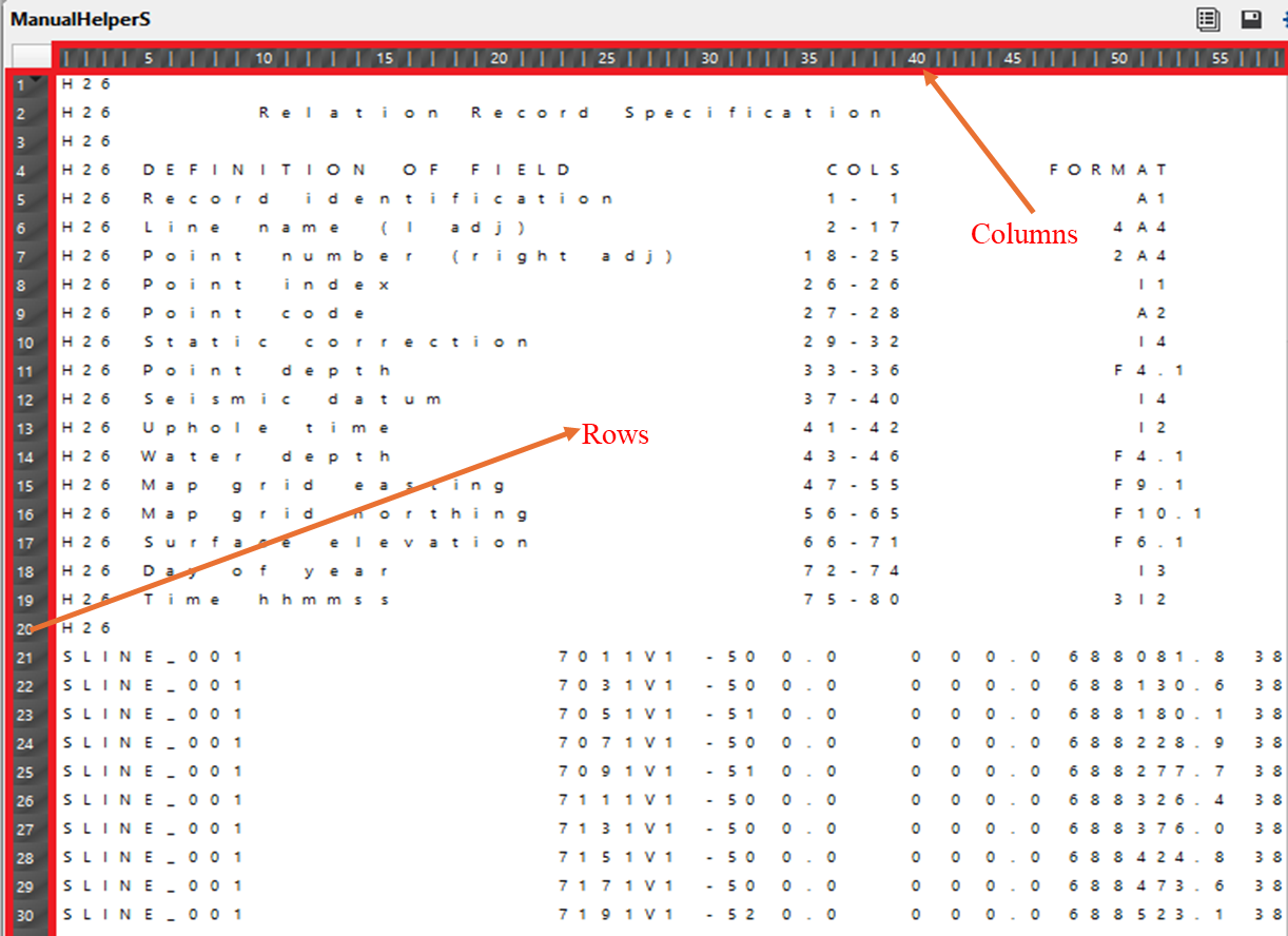
If the user wants to make the changes in the parameters field of "Read S file scheme", it can be done by holding MB1 and drag until the required field position, right click on it and select "Set as line range". It will replace the existing position to the new column positions in of line position.
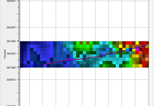
Likewise, the user can change the column positions from the remaining two files i.e. Manual Helper R & Manual Helper X. Load geometry from SPS module also generates the Elevation map on the location map.
![]()
![]()
Read additional offsets file - If there are any additional offsets like perpendicular offset and inline offset information in a file, provide the input file by click on in this action item. Upon selecting this option, a pop-up window opens up. Provide the input file.
Create sps Trace headers - This will create virtual trace headers according to S,R & X files.
![]()
![]()
YouTube video lesson, click here to open [VIDEO IN PROCESS...]
![]()
![]()
Yilmaz. O., 1987, Seismic data processing: Society of Exploration Geophysicist
 * * * If you have any questions, please send an e-mail to: support@geomage.com * * *
![]()