Calculating matched filter operator
![]()
![]()
What is a Matched Filter?
A matched filter is a processing operator designed to maximize the Signal-to-Noise Ratio (SNR) of a known seismic wavelet. It is the optimal filter (in the least-squares sense) for detecting or enhancing a signal whose shape is known or estimated.
A matched filter is the time-reversed version of the desired signal (wavelet) used as a convolution operator to enhance that signal in the noisy trace.
How Does a Matched Filter Work?
The matched filter works by cross correlating the seismic trace with a reference wavelet: y(t) = x(t) * w(-t)
Where:
•x(t) = recorded seismic trace
•w(t) = known or estimated wavelet
•w(-t) = time-reversed wavelet (the matched filter)
•* = convolution
•If the wavelet in the recorded data matches the reference wavelet in the filter constructive interference, SNR increases.
•If the noise is random, it does not correlate which means suppressed.
This is why matched filtering is widely used after correlation, deconvolution, or vibrator processing.
Where is Matched Filtering used?
•Vibroseis processing (matching pilot sweep to correlated data)
•Post-stack enhancement (boosting a specific reflection event)
•Target detection
•Deconvolution & wavelet shaping
Mathematical Basis of Matched filter design and application
1. Filter Design
Given a reference wavelet w(t), the matched filter h(t) is: h(t) = w(-t) i.e., reverse the wavelet in time.
If designing in frequency domain: H(f) = W*(f) Where W*(f) = complex conjugate of the wavelet spectrum.
2. Applying the Filter
Filtered trace = convolution of seismic trace with matched filter: y(t) = x(t) * h(t)
Or equivalently, cross-correlation: Y(t) = x(t) . w(t)
Estimation of the Filter and application on seismic data
Step 1 — Estimate or choose the wavelet
Sources:
•Pilot sweep (Vibroseis)
•Statistical wavelet extraction
•Near-offset wavelet analysis or Near Field Hydrophone
•Well tie wavelet
Step 2 — Create the Matched Filter
Time domain
Wavelet = [w1, w2, w3, ... wn]
Matched filter = [wn, ..., w3, w2, w1] - Reverse the wavelet:
Frequency domain
Take FFT of the wavelet and use its complex conjugate.
Step 3 — Apply to seismic data
Use convolution: Y(t) = X(t) * H(t)
Or in frequency domain: Y(f) = X(f) . H(f)
![]()
![]()
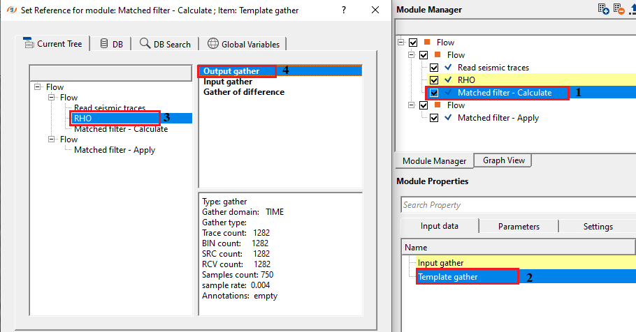
Input gather - connect/reference to the input gather that needs to be matched with template gather
Template gather - this is the source gather which acts as a template gather. Based on this gather, input gather is matched.
![]()
![]()
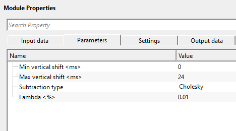
Min vertical shift - this parameter is useful in filter design. It controls how much pre-lag the filter can impose. Specify the minimum vertical shift value. In case the output shifts due to the minimum vertical shift, the user must keep the minimum vertical shift value as default which is ZERO (0).
Max vertical shift - specify the maximum vertical shift to be considered. This parameter controls how long the filter is allowed to look ahead. Within these limits, the algorithm works while designing the filter operator.
Solver type { SVD, Cholesky, Lsqr } - these are system of linear equations used to calculate the filter operator.
SVD - it is very stable and controls tiny singular values. This is more preferred when designing filters from a very noisy sweeps.
Cholesky - it is less stable compared to SVD. It is used when trace to trace matching is required and input wavelet is clean(not noisy) however it fails when the matrix is singular (expects positive symmetric definitive matrix).
LSQR - it is an iterative solver for large problems. It is used when designing filters for large number of traces. It is good for sparse systems and stability wise less compared to SVD but better than Cholesky.
Lambda - this is a damping/stabilization parameter. It stabilizes the inversion and controls the smoothness of the filter. Smaller lambda value gives sharp filter response however it is very unstable. Larger values give smooth filter but may not fit for the desired wavelet.
![]()
![]()
Number of threads - One less than total no of nodes/threads to execute a job in multi-thread mode. Limit number of threads on main machine.
Skip - By default, FALSE(Unchecked). This option helps to bypass the module from the workflow.
![]()
![]()
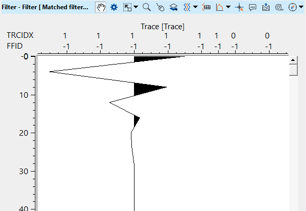
Filter - generates the output filter operator that should be used in Matched filter - Apply module.
There is no information available for this module so the user can ignore it.
![]()
![]()
In this example workflow, we design a matching filter operator that can be used in the later. To design that we need two datasets.
One is desired gather/Template gather.
Second one is source gather/Input gather.

For this exercise, we are taking a stack section and changing it's phase by using RHO module. Output gather from RHO module acts as a Template gather/Desired gather. Input gather from RHO module acts as Source/Input gather.
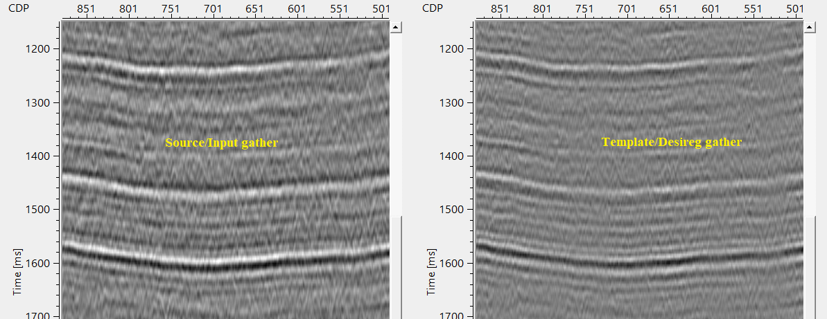

Setup the parameters and execute the module. It will generate 3 outputs vistas. Input gather, Template gather and filter. This filter is used further in the Match filter - Apply.
![]()
![]()
There are no action items available for this module.
![]()
![]()
YouTube video lesson, click here to open [VIDEO IN PROCESS...]
![]()
![]()
Yilmaz. O., 1987, Seismic data processing: Society of Exploration Geophysicist
 * * * If you have any questions, please send an e-mail to: support@geomage.com * * *