Converting zero or mixed phase wavelet into minimum phase
![]()
![]()
Phase conversion is very crucial step in Seismic data processing/imaging. If the phase of the data is not as client desired then we need to repeat the whole process from the beginning.
In Onshore and Offshore data acquisitions, we know the source. In the case of land we have Dynamite or Vibroseis as the source whereas Airgun is used as a source for Marine acquisition. For Airgun and Dynamite the source will be in minimum phase. Vibroseis data is in Zero phase and we need to convert it to minimum phase. Non symmetric, short duration and maximum energy (amplitude) at all frequencies are the characteristics of Minimum phase wavelet.
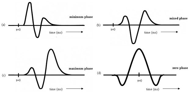
Deconvolution works best in minimum phase and it assumes that the data is in minimum phase. So either for land or marine, we should have a minimum phase wavelet prior to predictive deconvolution. For marine data, it will be helpful in attenuating the water reverberations.
In the case of Marine acquisition, source signature will be provided at the beginning of the survey and we call that as a far field source signature. If the far field signature is not provided then we can extract the source signature from the direct arrivals. Make sure not to confuse with the refracted energy. Take the far field source signature and add source/receiver ghost (if it doesn’t exist) and convolve them. Now we have to design a matching filter and make sure that the matching filter should be of the user objective. If you are working towards minimum phase conversion then the matching filter should be minimum phase only since the convolution of minimum phase wavelet and zero phase wavelet will result in a mixed phase.
![]()
![]()
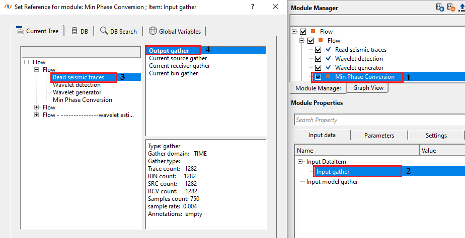
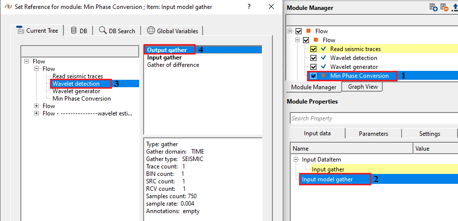
Input DataItem
Input gather - provide the input gather (either zero phase or mixed phase) that needs to be converted to minimum phase.
Input model gather
![]()
![]()
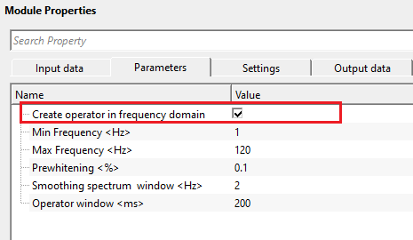
Create operator in frequency domain - by default, FALSE which means the operator will be created in Time domain. In case of the frequency domain, the minimum phase operator is generated by creating amplitude spectrum followed by log amplitude spectrum. Later, Hilbert transform to get the minimum phase operator.
Create operator in frequency domain - false - it will create the operator in TIME domain. In case of time window, the user should provide the Operator window parameter values.
Convolution domain { Frequency, Time } - this section deals with convolution. Select the domain from the drop down menu.
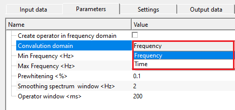
Frequency domain - it creates the minimum phase operator in frequency domain by truncating the operator at a certain time interval. The operator created in frequency domain controls ringing and filter length.
Time domain - the minimum phase operator created in the time domain with large operator length will be more accurate however it takes longer duration of time to compute.
Min Frequency - provide the minimum frequency value that should be considered in minimum phase filter design. Very low and higher frequency values creates noisy, ringing data in the Hilbert transformation.
Max Frequency - provide the maximum frequency. It will vary based on the sample interval of the data. If the input data is 2ms then the maximum frequency will be 125 Hz which is the Nyquist frequency.
Prewhitening - add small percentage of while noise to have a stable operator.
Smoothing spectrum window - Hilbert transformation requires smooth spectrum to avoid any unstable/ringy/noisy output. Prior to the hilbert transformation, the spectrum should be smooth. Provide a smoothing spectrum window value.
Operator window - this parameter is required when the operator is calculated in time domain. It sets the time domain operator and length of the minimum phase operator. This helps in stabilizing the operator, avoids any ringing effect etc.
![]()
![]()
Auto-connection - By default, TRUE(Checked).It will automatically connects to the next module. To avoid auto-connect, the user should uncheck this option.
Bad data values option { Fix, Notify, Continue } - This is applicable whenever there is a bad value or NaN (Not a Number) in the data. By default, Notify. While testing, it is good to opt as Notify option. Once we understand the root cause of it,
the user can either choose the option Fix or Continue. In this way, the job won't stop/fail during the production.
Notify - It will notify the issue if there are any bad values or NaN. This will halt the workflow execution.
Fix - It will fix the bad values and continue executing the workflow.
Continue - This option will continue the execution of the workflow however if there are any bad values or NaN, it won't fix it.
Calculate difference - this option creates the difference display gather between input and output gathers. By default Unchecked. To create a difference, check the option.
Skip - By default, FALSE(Unchecked). This option helps to bypass the module from the workflow.
![]()
![]()
Output DataItem
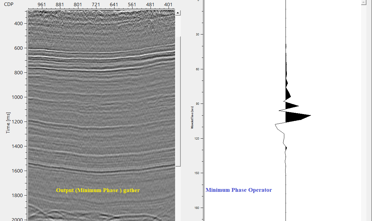
Output gather - outputs minimum phase converted output gather.
Gather of difference - generates difference gather after minimum phase conversion.
Output operator - generates minimum phase operator.
There is no information available for this module. So the user can ignore it.
![]()
![]()
In this example workflow, we are converting a zero phase gather into a minimum phase gather. To confirm the input data is in zero phase, we use "Wavelet detection" module and extract the wavelet phase. It should give us a zero phase wavelet.
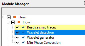
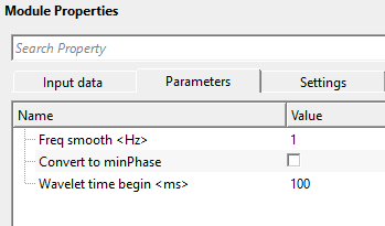
After executing the module, take a look at the output gather of Wavelet detection module.
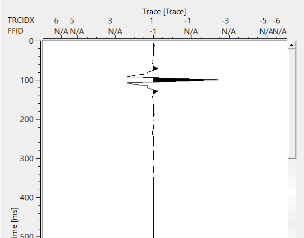
This output confirms that the input data is in zero phase. Now we can use this wavelet as a model gather or we can design a zero phase wavelet using "Wavelet generator" module. This module by default uses Ricker wavelet. The user can choose many wavelets/Impulse type from the drop down menu.
Make sure that the output wavelet should match with the same number of samples and sample interval of the input data.
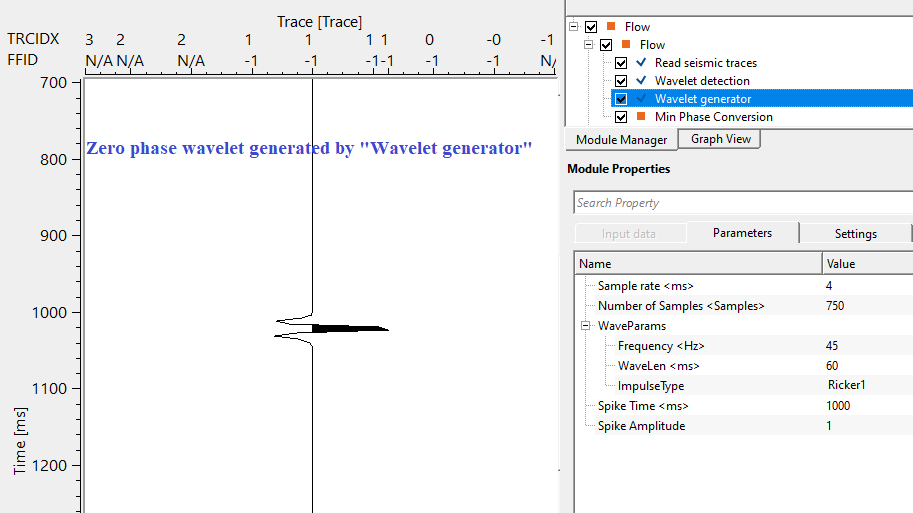
The user can use either of the wavelet (detected by Wavelet detection or generated by Wavelet generator) as a modeled gather.
Choose the right domain and correct parameters as per the data requirement and execute the module. It will generate input gather, output gather, difference gather (if opted in the settings tab) and Minimum phase filter operator.
![]()
![]()
There are no action items available for this module.
![]()
![]()
YouTube video lesson, click here to open [VIDEO IN PROCESS...]
![]()
![]()
Yilmaz. O., 1987, Seismic data processing: Society of Exploration Geophysicist
 * * * If you have any questions, please send an e-mail to: support@geomage.com * * *
![]()