Velocity converting from gather, ASCII, other to -> internal format
![]()
![]()
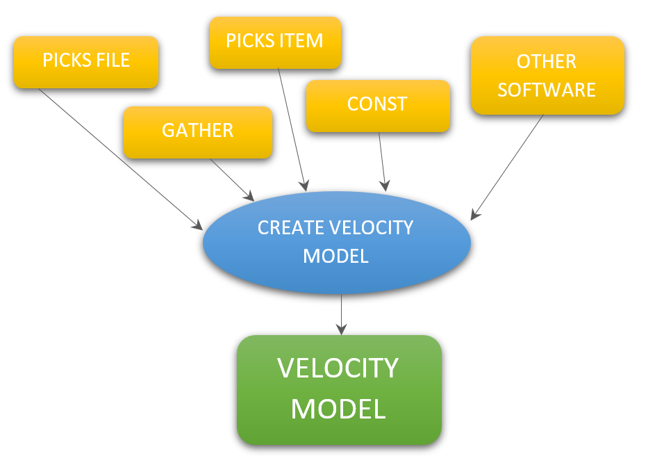
This module creates a velocity model in an internal Geomage format. It accepts various types of input data, such as gathers, SEG-Y handles, picks collections, and pick files. The module generates a velocity model that can be used by subsequent procedures that require a velocity model, such as NMO, Kirchhoff PreSTM (2D/3D), and others.
![]()
![]()
Input velocity types - choose type of input velocity data:
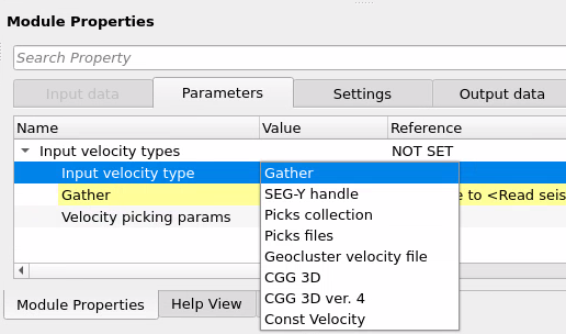
Input velocity type :
Input velocity data can be set as:
•Gather - seismic gather data;
•SEG-Y handle - seismic data on a disk;
•Picks collection - picking item is output data from other module (for example its an output file from Stack imaging module), or from Load item module;
•Picks file - ASCII file of velocity picking (for example its an output file from Stack imaging module);
•Geocluster velocity file - velocity format of the Geocluster processing software;
•CGG 3D - velocity format of 3D data CGG company;
•CGG 3D ver. 4 - velocity format version 4 of 3D data CGG company;
•ProMAX - velocity data exported from Halliburton ProMAX processing software in List/Table text format;
•Const Velocity - constant velocity format.
Gather - link to input velocity gather in case Gather options is selected.
SEG-Y handle - link Output SEG-Y data handle from Read SEG-Y traces / Read seismic traces.
Trace headers - link Output trace headers from Read SEG-Y traces / Read seismic traces.
Velocity picking params - parameter group that controls how velocity picks are linked and how they are spatially interpolated across the survey area. Applies when the input type is Picks collection, Picks files, Geocluster velocity file, CGG 3D, CGG 3D ver. 4, or ProMAX.
This group contains the velocity picking link and the spatial interpolation settings that determine how velocity values are estimated between pick locations. The chosen interpolation method and its parameters have a direct effect on the smoothness and accuracy of the resulting velocity model across the entire survey grid.
Velocity picking - link velocity to a picking item, for example from the Stack imaging module or loaded via the Load item module. This connection is required when the input type is set to Picks collection.
The velocity picking item is a structured collection of time-velocity pairs digitized at individual CMP or bin locations. Once linked here, the module reads all picks and applies the selected interpolation method to build a continuous velocity model across the survey grid.
Interpolation type - select the spatial interpolation method used to fill velocity values between pick locations. Options: Kriging (default) or Triangulation:
Kriging is a statistical interpolation method based on the assumption that spatial data points are correlated. It creates an optimal surface that minimizes prediction errors by considering both the distance between data points and their spatial correlation structure.
Triangulation - In this interpolation method, a network of triangles is created from a set of data points. One of the commonly used triangulation methods for interpolation is Delaunay triangulation. It ensures that no data point lies inside the circumcircle of any triangle in the mesh, which results in a set of non-overlapping triangles. In this network, every point lies on the edge of one of the triangles. Linear interpolation is then applied, where the value at any point inside a triangle is estimated by taking a weighted average of the three vertices of the triangle.
For most surveys, Kriging is the preferred choice because it accounts for spatial correlation between picks and produces geologically smoother velocity models, especially in areas of sparse pick coverage. Use Triangulation when picks are densely and evenly distributed across the survey and you want fast, locally exact interpolation without a correlation-based smoothing model.
Kriging covariance type - defines the spatial correlation model used in Kriging. Default: Exponential. Available types: Exponential, Spherical, and Gaussian. The Exponential model decays gradually and is well-suited to most velocity fields. The Spherical model reaches zero correlation at a finite range and can better represent layered geology. The Gaussian model is very smooth and best for gradually varying velocity anomalies.
Kriging range <meters> - specifies the range of influence (in meters) for spatial correlation in the Kriging model. Default: 100,000 m. A larger range results in smoother interpolation over long distances, while a smaller range captures more local velocity variations. Set this value to approximately the average distance between velocity pick locations for best results. For typical 3D surveys with CMP spacing of several kilometers, values between 5,000 m and 50,000 m are common.
Kriging number of points - defines the maximum number of neighboring pick locations considered when estimating velocity at each point. Default: 20. Minimum: 1. Increasing this value improves interpolation accuracy by considering more surrounding data, but will increase computation time. For sparse pick distributions, use higher values (30 or more) to ensure sufficient neighbors are found; for dense surveys, the default of 20 is usually adequate.
Gather - link to input velocity gather in case the Gather option is selected. The gather data must contain velocity values as trace amplitudes, with the time axis representing the vertical velocity axis.
CDP match - controls how CDP numbers in the ProMAX velocity file are matched against CDP numbers in the connected trace headers. Available only when input type is set to ProMAX. Options: Exact (default) or Nearest.
Set to Exact when the CDP numbers in the ProMAX file exactly match those in the survey geometry. Set to Nearest when CDP numbers may differ slightly between the ProMAX export and the project geometry — in this mode, each ProMAX CDP is matched to the closest CDP number found in the trace headers. Use Nearest if some ProMAX CDPs are not found with Exact matching.
Picking files - add a path and file with velocity picking in Geomage format (for example, a file created by the Stack imaging module). Multiple files can be added; when more than one file is specified, they are automatically merged into a single combined velocity model using the Output file name as the merged output path.
File path - path to a velocity picking file in Geomage format (.corr or .txt). Add one entry per file. Accepted formats: .corr, .txt. Files must be version 3 or higher; older formats will not load correctly.
Output file name - path and file name (on disk) where the converted velocity picking will be saved in Geomage internal format (.corr). Required when loading multiple Picks files (the merged result is written here) or when converting from an external format such as Geocluster, CGG 3D, or ProMAX so that a copy in Geomage format is preserved for future use. Optional when loading a single Picks file.
Input file name - path and file name of the external velocity file to import. Used for Geocluster (.corr, .vel, .asc, .txt), CGG 3D, CGG 3D ver. 4, and ProMAX input types. For Geocluster, this is the main velocity picking ASCII file. For CGG 3D formats, this is the velocity picking file (paired with the Input geometry file name). For ProMAX, this is the exported List/Table text file.
Input geometry file name - path and file name of the CGG geometry file (.txt) that provides the XY coordinates for each inline/crossline location in the velocity file. Required together with the Input file name when the input type is CGG 3D or CGG 3D ver. 4. Without this file, the module cannot assign spatial positions to the velocity picks.
Const. Velocity - define a single constant velocity value in m/s that will be applied uniformly to the entire dataset. Default: 1500 m/s. Use this mode for quick testing, for water-column velocity in marine data, or when a laterally homogeneous starting model is needed before velocity analysis.
![]()
![]()
Skip - switch-off this module (do not use in the workflow).
![]()
![]()
Velocity model - the output velocity model in Geomage internal format. This item is connected to downstream modules that require a velocity model, such as NMO correction, Kirchhoff PreSTM (2D or 3D), Radon demultiple, CRE tomography, and others.
The velocity model encapsulates the full time-velocity field derived from the selected input source. Depending on the input type, it may be stored as a direct gather reference (Gather / SEG-Y handle modes) or as an interpolated picking model (all other modes). The output does not produce a separate visual display window in the workspace — it is a data connector only, and is used exclusively as an input to other processing modules.

The Create velocity model module does not produce a visual display window in the workspace. Its output velocity model is a data item that flows downstream through module connections. To use it, connect the Velocity model output port to the velocity input port of the target module (e.g., NMO, Kirchhoff migration, or Radon).
When loading velocity from external software formats (Geocluster, CGG 3D, ProMAX), it is recommended to always provide an Output file name so that the converted picking is saved to disk in Geomage format. This avoids re-reading and re-converting the external file on subsequent workflow runs.
For the CGG 3D and CGG 3D ver. 4 formats, both the velocity file and the geometry file are required. If the module reports that geometry could not be found for certain inline/crossline locations, check that the correct geometry file is connected and that the line and SP numbering conventions match between the two files.
When using the SEG-Y handle input type, the seismic data must be in post-stack format (one trace per bin). If the trace vector contains multiple traces per bin, the module will return an error. Ensure the velocity SEG-Y file has been stacked or sorted to one-trace-per-CMP before using this mode.
![]()
![]()
In this example we use converted velocity model in Radon module as input data set. Read velocity model as seismic gather and convert ir via Create velocity model. In this case we should select Gather option in the Input velocity type:
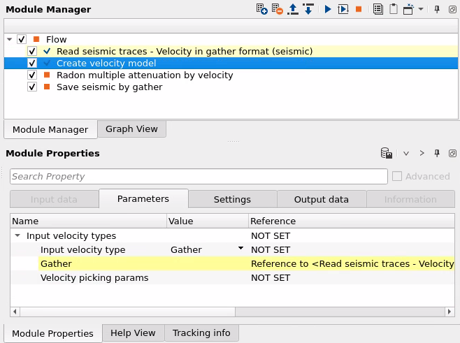
Next, link input Velocity model in the radon module, use output froCreate velocity model as its shown below:
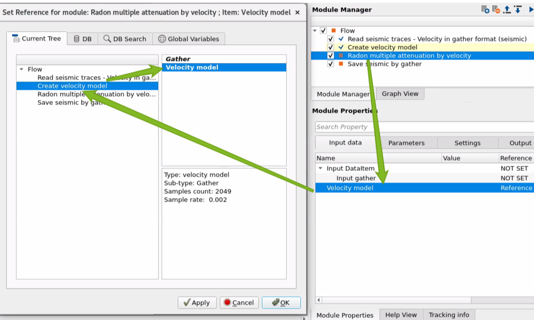
There is no output Visual Vista Items (Windows) from the module, but only an output data set that can be used in other modules as input.
![]()
![]()
 If you have any questions, please send an e-mail to: support@geomage.com