Description
RTM Stands for Reverse Time Migration
If we know the seismic image at a shot time T and we have the velocity field information, then we can predict the seismic wavefield at time T + dT or T - dT. This is the basis behind forward and reverse wavefield extrapolation techniques.
The source wavefieldis created at the shot location by propagating forward in time. The receiver wavefieldis obtained by propagating the recorded wavefield from its boundary (the recording surface) into the earth with time running backward. Because of the receiver wavefield back propagation, we call this technology as Reverse Time MigrationThe image is typically constructed by taking the zero-lag cross-correlation of the extrapolated source and receiver wavefields, i.e., the “same time same place” imaging principle. Raypaths that are modelled in the both the Source and Receiver wavefields (i.e diving waves and reflections from velocity contrasts present in the velocity model), will correlate at all travel times leading to a low frequency smear in the data.
If we can explain RTM in more simplistic way:
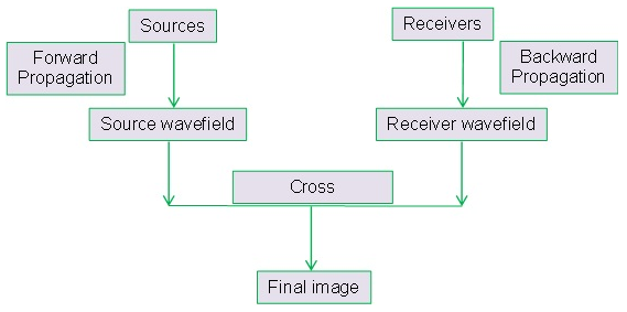
Figure 1. Schematic Diagram of RTMwork flow
Source Wave field forward modeling
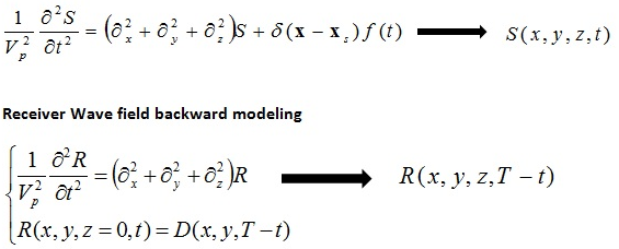
Where T is the maximum recorded time.
Input: Output File name
Imaging Condition Type
DX
Use Wavelet
Frequency
Time Step
Time Step for correlation
RTM works in shot domain and migrate the data shot by shot. Also we need regularized shot gathers.
RTM stores both Source Wavefield and Receiver Wavefield and we need more memory. To properly manage our resources, clip the values above the water bottom so that we can reduce the run time and disk space. Also RTM run time is directly proportional to the trace time. So depending on output depth and migration velocity, using the entire length of the input traces might not be necessary for migration.