Merging multiple seismic trace headers into a single output trace header
![]()
![]()
What is Geometry Concatenation?
Geometry concatenation means merging or joining multiple geometry-defined datasets into a single, continuous dataset — while preserving or re-indexing all spatial relationships (CDP, line, shot, receiver, bin numbers).
It’s essentially concatenation of both the seismic traces and their geometry headers to form a unified geometry database.
Why We Need Geometry Concatenation
Seismic surveys are often acquired or processed in segments:
•By line (2D)
•By swath or patch (3D)
•By acquisition campaign (phase 1, phase 2, etc.)
Each segment has its own geometry file or coordinate system.
To perform combined processing — such as migration, stacking, or 3D cube building — all geometry segments must be concatenated into one consistent geometry framework.
In Simple Terms:
Geometry concatenation = merging multiple geometry-defined lines or files into one master geometry, so the software treats them as a single continuous survey.
When Do We Perform Geometry Concatenation?
Stage |
Purpose |
|---|---|
After defining geometry for multiple lines/swaths |
To combine all into a single project geometry database |
Before sorting to CMP/CDP |
Ensures all traces share a consistent bin numbering system |
Before merging processing outputs |
After separate line processing, to create full-field stacked or migrated volume |
When regridding or reprojecting coordinates |
To unify datasets acquired in different projections or bin sizes |
During 3D processing preparation |
To create a single inline–crossline index over the full 3D area |
How Geometry Concatenation Works?
Step-by-step process:
1.Load geometry-defined datasets (e.g., each line or swath with source–receiver headers).
2.Check consistency — same coordinate reference system, units, and bin parameters.
3.Merge geometry tables — combine all source/receiver/CDP info into one master table.
4.Reassign unique identifiers — update:
oLine IDs (avoid overlaps)
oCDP ranges (ensure continuity)
oTrace sequence numbers (continuous numbering)
5.Write concatenated geometry to the merged SEG-Y or processing project.
6.QC check — verify fold map, midpoint map, and coordinate continuity.
Why Geometry Concatenation Is Necessary
a) For complete area coverage
Without concatenation, each dataset remains isolated; you can’t process or image across line boundaries.
b) For stacking and migration
Stacking requires consistent CDP numbering across the entire survey — geometry concatenation ensures that.
c) For 3D cube building
A 3D volume (inline × crossline) can only be generated after concatenating all geometry patches into a unified coordinate grid.
d) For interpretation continuity
Concatenated geometry ensures reflectors and structures align across boundaries.
Example (2D Line Geometry Concatenation)
Suppose you have:
•Line 1: CDP 1001–1500
•Line 2: CDP 1001–1500 (same numbering, different coordinates)
If you simply join them, CDPs overlap — causing confusion.
After geometry concatenation, CDP numbering becomes:
•Line 1: CDP 1001–1500
•Line 2: CDP 2001–2500
No overlap, consistent geometry — both lines now part of the same project.
Important Checks Before Concatenation
•Ensure coordinate system consistency (e.g., UTM Zone 43N).
•Same datum and projection.
•Same bin size and azimuth.
•No duplicate CDP or line IDs.
•Recreate or verify sequence numbers and offsets after concatenation.
•Run fold and coverage QC maps to confirm continuity.
![]()
![]()
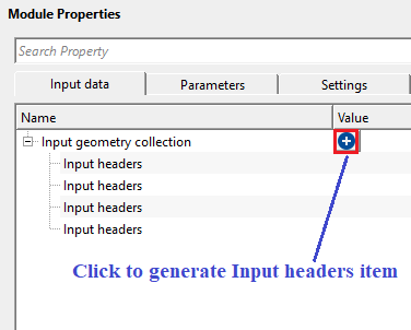
Input geometry collection - provide the input trace headers of each input file. By clicking the ![]() icon, it will add Input trace headers item. If there are multiple input file geometries to be concatenated then the user should click on the
icon, it will add Input trace headers item. If there are multiple input file geometries to be concatenated then the user should click on the ![]() icon multiple times.
icon multiple times.
![]()
![]()
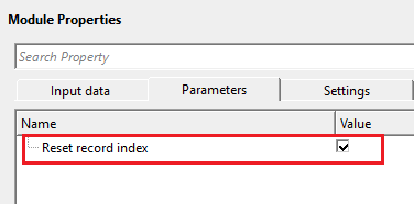
Reset record index - each input file will have it's own trace indexing numbers. To make them unique, reset the trace/record index numbers otherwise, it will be confusing and the output geometry is not correct. By default, TRUE (Checked).
![]()
![]()
Skip - By default, FALSE(Unchecked). This option helps to bypass the module from the workflow.
![]()
![]()
Output trace headers - generates concatenated output trace headers.
![]()
![]()
Different additional headers option - controls how the module handles differences in non-standard (additional) header fields between the input geometry datasets. When different datasets carry different sets of custom header fields, a conflict arises during concatenation. Choose Check to verify that all input datasets share exactly the same additional headers before merging — the module will report an error if a mismatch is detected, allowing you to correct the inputs before proceeding. Choose Remove additional headers on merge to automatically discard any non-standard header fields that are not present in all inputs, allowing the merge to complete even when the datasets have inconsistent custom headers. Use Check when data quality is critical and you want to be alerted to any header inconsistencies. Use Remove additional headers on merge when the datasets originate from different sources or processing flows and differences in custom headers are expected and acceptable. Default value: Check.
![]()
![]()
In this example workflow, we are reading 3 different 2D lines with different x,y coordinates.

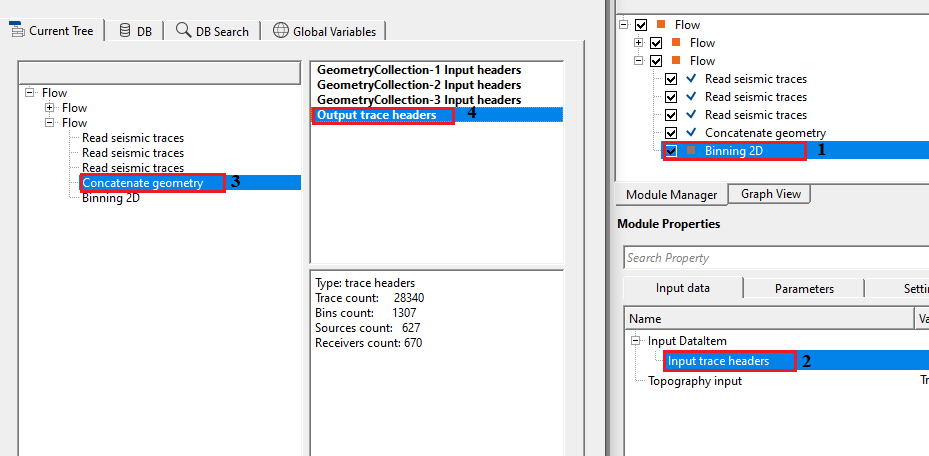
To concatenate all 3 of them and use the final output trace headers for further processing like Binning 2D in this case, we connect each seismic file Output trace headers to Input headers of Concatenate geometry module.

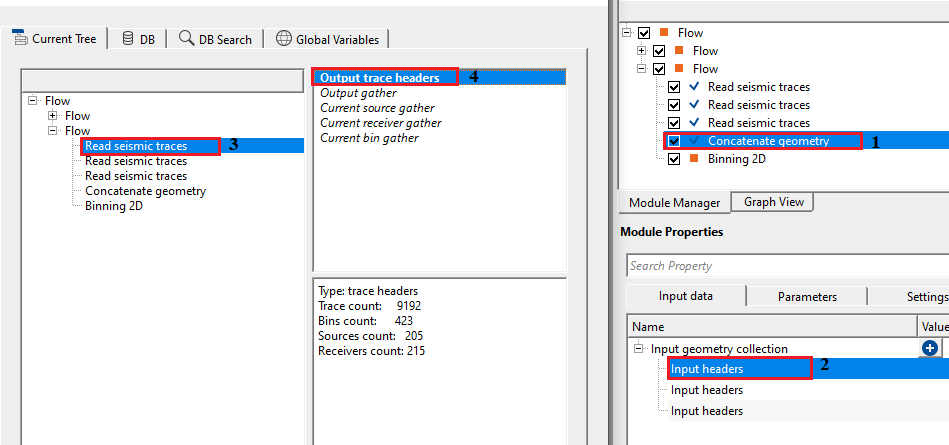
Likewise, connect other 2 also. In the first file, we've 9192 traces. In the 2nd file, we've 12930 traces and finally in 3rd file we've 6218 traces. After executing the Concatenate geometry, final output trace headers will have a combined trace count of 28340.
![]()
![]()
There are no action items available for this module.
![]()
![]()
YouTube video lesson, click here to open [VIDEO IN PROCESS...]
![]()
![]()
Yilmaz. O., 1987, Seismic data processing: Society of Exploration Geophysicist
 * * * If you have any questions, please send an e-mail to: support@geomage.com * * *
![]()