![]()
![]()
In seismic data processing, every source (shot point) and receiver (geophone or hydrophone) belongs to a specific line — known as a source line or receiver line. These line IDs help define the geometry of the survey — i.e., where each shot and receiver physically lies in space.
Sometimes, due to navigation errors, field entry mistakes, or survey mergers, the line IDs get recorded incorrectly or inconsistently. So, correction of Source/Receiver Line IDs is necessary. What does it means is that updating or fixing the incorrect, missing, or mismatched line identifiers for sources and receivers so that each belongs to its correct physical line.
Navigation errors in the field
– GPS drift or manual entry errors can cause source/receiver coordinates to appear under the wrong line ID.
– Example: Source at inline 120 accidentally logged as inline 220.
Merging multi-crew or multi-vintage surveys
– Different crews may use different line numbering systems (e.g., 1000-series vs. 2000-series).
– Line IDs must be unified for consistent geometry.
Data loading into processing systems (e.g., SEG-Y, SPS, or navigation databases)
– Incorrect line IDs cause traces to map into the wrong bins.
– This produces fold irregularities, wrong offsets, and artifacts in stacking/migration.
Misalignment between source and receiver geometry
– When source and receiver line IDs do not match spatially, the trace midpoint and binning will be wrong.
How to do the correction?
•Plot the existing source and receiver line IDs & identify the incorrect or mismatched positions
•Compare the navigation coordinates with pre-survey/plot survey coordinates. Assign each source and receiver to the their correct line based on spatial proximity
•Update the source and receiver line IDs by manual or automatic assignment like kriging interpolation etc.
•After correction, recompute offsets, mid points, cmp positions, inline and crosslines etc.
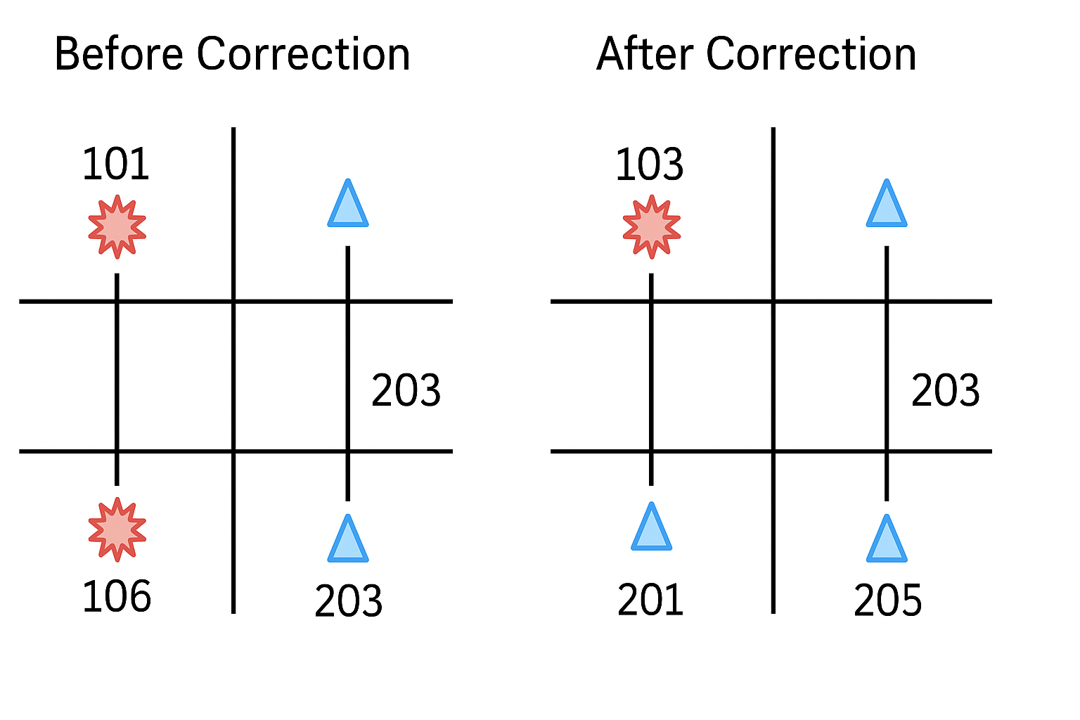
Before Correction:
•The grid lines represent survey lines — think of them as the inline and crossline directions in a 3D seismic survey.
•The red star symbols represent sources (shot points).
•The blue triangles represent receivers (geophones or hydrophones).
•Each intersection on the grid corresponds to a nominal source or receiver position.
1.Incorrect Line IDs:
oThe red source points are labeled with Line IDs 101 and 106, which are incorrect.
oThese IDs don’t match the physical position where they lie on the grid.
oFor example:
▪The upper shot labeled 101 is actually located closer to Line 103.
▪The lower shot labeled 106 lies closer to Line 201.
2.Receiver Lines Misaligned:
oReceivers on the right both have Line ID 203, but they are positioned on different physical receiver lines.
oThis indicates that field navigation data (or SPS header data) had misassigned or duplicated line numbers.
After Correction:
•The same grid is retained — meaning the physical geometry (X, Y coordinates) hasn’t changed.
•What’s changed is the line identification numbers associated with those positions.
Source Line IDs Updated:
•The upper source was corrected from 101 → 103
Now matches the correct line (upper grid line).
•The lower source was reassigned to a new receiver line (not shown explicitly) for correct alignment.
Receiver Line IDs Updated:
•The lower-left receiver changed from 203 → 201, matching its actual line.
•The lower-right receiver updated from 203 → 205, now belonging to its own correct receiver line.
![]()
![]()
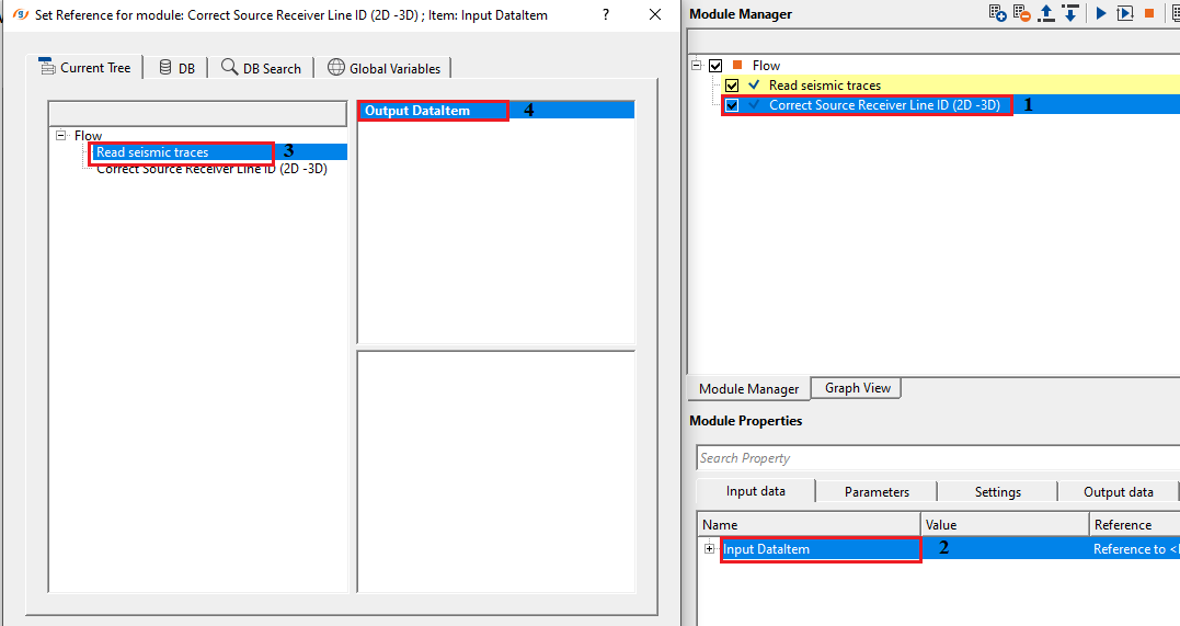
Input DataItem
Input trace headers - connect/reference to Output traces of Read seismic traces/Read SEG-Y traces or any corresponding module which got Output trace headers
Connect this input to the Output trace headers of a preceding module such as Read SEG-Y traces or any geometry-assignment module. The module reads the source and receiver XY coordinates stored in each trace header. These coordinates are the basis for the automatic line-ID reassignment — the module does not use the existing line numbers from the headers; it derives new ones purely from the spatial positions of sources and receivers.
![]()
![]()
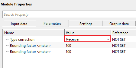
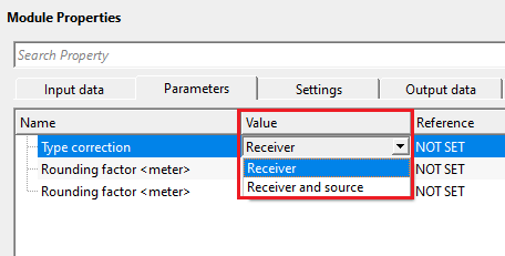
Type correction { Receiver, Receiver and source } - select the type of correction. By default, Receiver.
This parameter controls which geometry elements have their line IDs recomputed. Select Receiver to correct only receiver line identifiers while preserving the original source SP numbers from the input headers. This is the appropriate choice when source positions are already correctly defined and only the receiver line assignments are erroneous. Select Receiver and source to recompute line IDs for both sources and receivers simultaneously. Use this option when both the shot-point line numbers and receiver line numbers are unreliable or missing, for example after merging surveys from different crews that used incompatible numbering conventions.
Rounding factor - If distance between two receiver is less then given distance,the two receivers will have the same number. This is useful in avoiding fractional Receiver SP numbers. By default, 100.
The Rounding factor for receivers sets the spatial snapping distance (in metres) applied to receiver coordinates before line-ID assignment. When two receivers lie within this distance of each other, they are treated as being at the same physical position and receive the same line number. This prevents small GPS errors or sub-metre coordinate offsets from splitting receivers that belong to the same station into separate, spurious lines. The default value of 100 m suits typical land seismic surveys with station intervals of 25–50 m. For marine or high-resolution surveys with tighter receiver spacing, reduce this value to avoid merging genuinely distinct stations. For surveys with coarser spacing, a larger value can compensate for greater navigation uncertainty.
Rounding factor - If distance between two sources is less then given distance,the two sources will have the same number. This is useful in avoiding fractional SP numbers. By default, 100.
The Rounding factor for sources applies the same spatial snapping logic to shot-point positions. Source XY coordinates are snapped to the nearest grid multiple of this distance before the algorithm determines line membership. This is only active when Type correction is set to Receiver and source. The default value of 100 m is appropriate for standard land surveys. Adjust this value to match the nominal source spacing of your survey: set it smaller than the shot-point interval to avoid incorrectly merging adjacent sources onto the same line.
![]()
![]()
Auto-connection- By default, TRUE(Checked).It will automatically connects to the next module. To avoid auto-connect, the user should uncheck this option.
Skip - By default, FALSE(Unchecked). This option helps to bypass the module from the workflow.
![]()
![]()
Output DataItem
Output trace headers - generates updated output traces with corrected source and receiver line IDs.
The output carries the same traces as the input but with updated trace headers. For each trace, the source line ID and receiver line ID fields are overwritten with the newly computed values. In addition, the source-receiver offset is recalculated as the Euclidean distance between the corrected source and receiver positions, with sign applied based on the relative SP-number order along the line. Connect this output to the next processing module, such as a geometry QC display or a binning module.
The Correct Source Receiver Line ID (2D-3D) module automatically reassigns line identifiers to sources and receivers based solely on their recorded XY coordinates. It is designed to fix incorrect, missing, or inconsistent line numbers in trace headers that arise from field entry errors, GPS navigation inaccuracies, or the merging of surveys with incompatible numbering schemes. The module works on both 2D and 3D survey geometries.
The algorithm proceeds in the following steps. First, it reads all unique source and receiver positions from the input trace headers. If a Rounding factor is set, coordinates are snapped to the nearest grid multiple of that distance; this merges positions that are nominally the same station but differ by small navigation errors. Next, the module identifies a starting reference point — the position that lies furthest from the geometric centre of all stations — and sorts all remaining stations by their distance from that reference, walking outward in order. A sequential line number is assigned to each station in this ordered sequence. For receiver-only mode, source SP numbers from the original headers are preserved and only the receiver line assignments are updated.
After line IDs are assigned, the module recalculates the source-receiver offset for every trace as the straight-line distance between the corrected source and receiver positions. The sign of the offset is set negative when the receiver SP number is lower than the source SP number along the line, following the standard seismic convention. The corrected headers are passed to the output and can be visualised immediately on the Sources SP and Receivers SP map views built into the module.
Use this module early in the geometry QC workflow, after loading raw field geometry but before binning or any offset-dependent processing. It is particularly valuable when working with data imported from SPS files or SEG-Y files whose headers contain misassigned line numbers, or when combining data from multiple acquisition crews.
![]()
![]()
![]()
![]()
There are no action items available for this module.
![]()
![]()
YouTube video lesson, click here to open [VIDEO IN PROCESS...]
![]()
![]()
Yilmaz. O., 1987, Seismic data processing: Society of Exploration Geophysicist
 * * * If you have any questions, please send an e-mail to: support@geomage.com * * *
![]()