Load geometry from UKOOA P1/90
![]()
![]()
One of the widely used standard Marine navigation data is UKOOA(United Kingdom Offshore Operators Association) P1/90. It is the standard format for any towed streamer acquisition. It is a single file which consists of source and receiver information. In the file, source coordinates, source water depth, receiver coordinates, receiver depths are available. Inside the file, all the specifications about Geodetic coordinate systems, cable information, client information, Grid origin, scale factors etc are available.
Here we are displaying some of the information related to source and receivers.
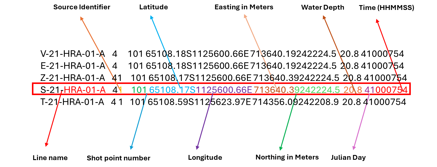
In this below image, following source information is specified in the P190 file.

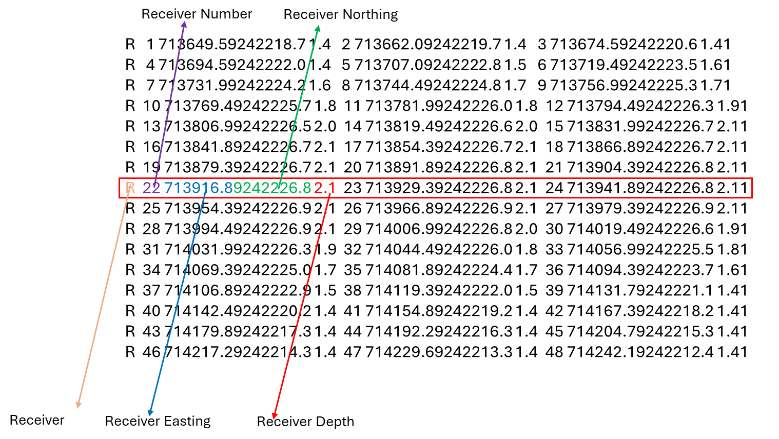
Similarly, Receiver information is available in the P190 file.

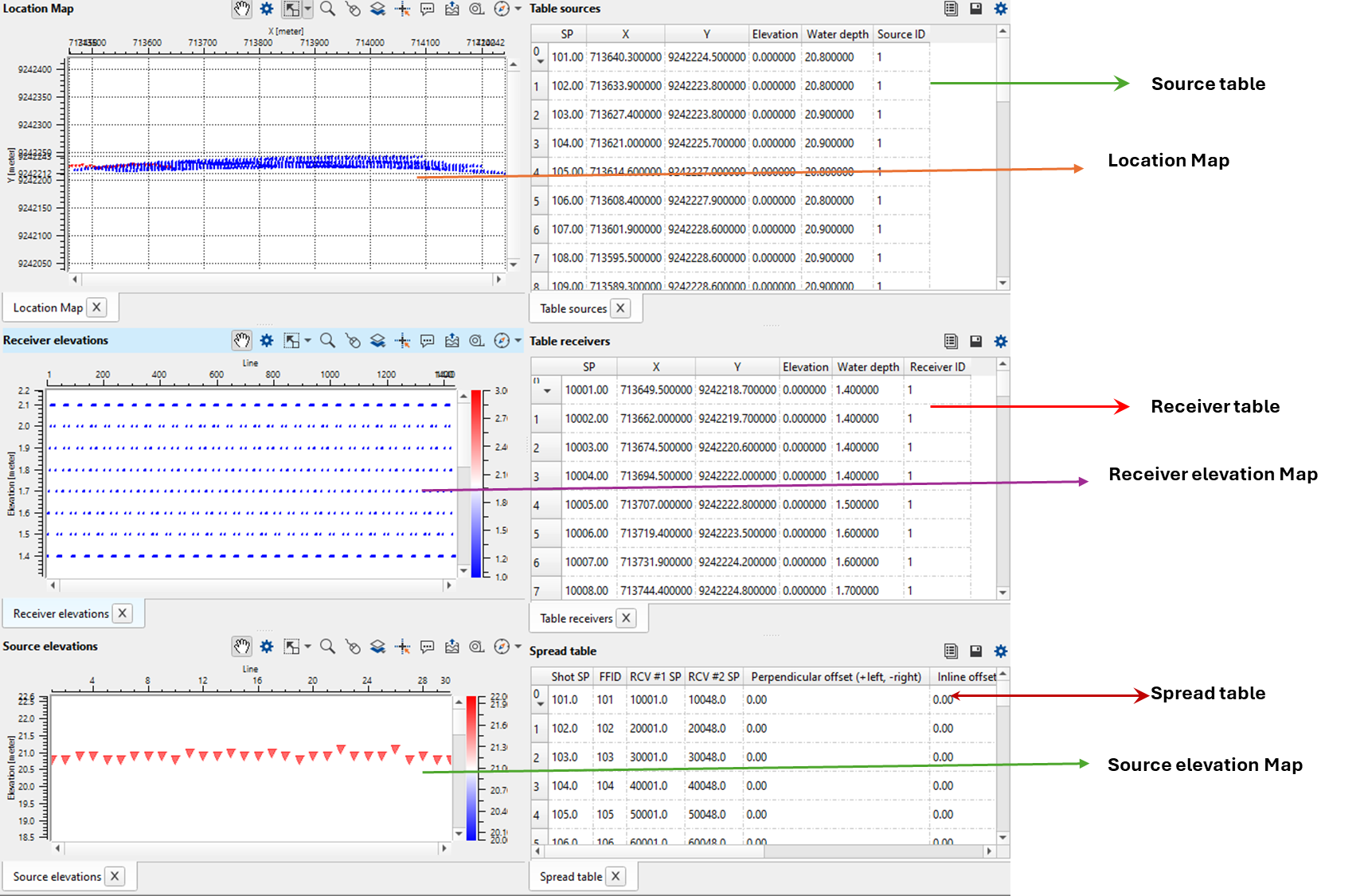
The module read UKOOA P1/90 file format creates geometry tables for "Geometry application" module. It creates views that allow to check geometry visually.
![]()
![]()
Input type { Single file, File list } - There are two options available for the input selection. When the user selects, single file option, then the user should browse through the file path and locate it in the "Input navigation file" parameter
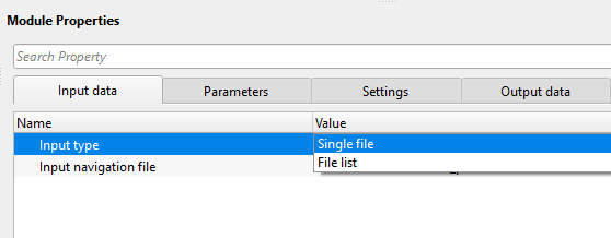
Input navigation file Full path of a single UKOOA P1/90 file
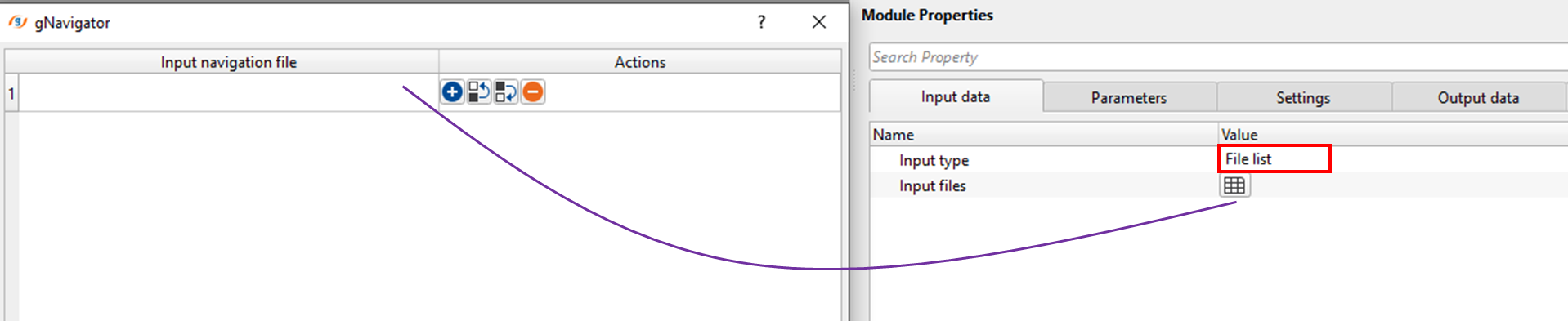
Input files - When the Input type is File list, then the user should click on the table icon. It will open a new window. Inside the Input navigation file field, browse the input files and select it. For multiple files, hold Shift key and select all the files.
![]()
![]()
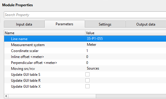
Line name - In case of multi lines, it gives the possibility to select specific line. For single line, it will display the line name.
Measurement system - Choose the desired measurement system from the drop down menu. Imperial (Feet) or Metric (Meter). By default, Meter.
Coordinate scalar - By default 1. If the user wants to multiply the coordinates by any factor, specify the value here.
Inline offset - Provide the Inline offset information if available
Perpendicular offset - Provide the perpendicular offset information if available
Moving src/rcv - Choose whether the Source is moving or Receiver.
Update GUI table S - If checked, it will update the table Sources.
Update GUI table R - If checked, it will update the table Receivers
Update GUI table X - If checked, it will update the relation file.
![]() Please pay attention to "Update GUI table of S,R,X" - For 2D lines it is okay to enable/check this option. For large 3D surveys, please choose source and receiver. Spread may take a lot of time and memory to create and display the tables.
Please pay attention to "Update GUI table of S,R,X" - For 2D lines it is okay to enable/check this option. For large 3D surveys, please choose source and receiver. Spread may take a lot of time and memory to create and display the tables.
![]()
![]()
Skip - By default unchecked. It is not necessary to skip this module.
![]()
![]()
Sources and receivers collection - This creates the source and receiver collection information which is further used in the Geometry application module.
Spread - Generates the spread information as an output. This spread information is used in assigning the geometry.
Bins collection "Q" header -
CMPs collection "C" header -
Sources geometry file table - Generates the source geometry file in tabular format. In this, we find source, source x and y, source water depth information.
Receivers geometry file table - Generates the receiver geometry file in tabular format. In this table, we find receiver, receiver x and y, receiver depth information.
Spread table - Generates the spread information file in tabular format. These tables can be exported by using Export table module. It consists of Shot SP, FFID, Receiver 1 SP, Receiver 2 SP etc.
![]()
![]()
Here is an example workflow where "Load geometry from UKOOA P1/90" is included in assigning geometry of a sail line.
1. Read SEG-Y Traces - This modules read the raw/field SEGY data
2. Load geometry from UKOOA P1/90 - Provide the input navigation file
3. Geometry application - This module gets the seismic data and navigation data from Read SEG-Y traces and Load geometry from UKOOA P1/90 modules respectively.
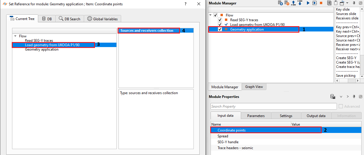
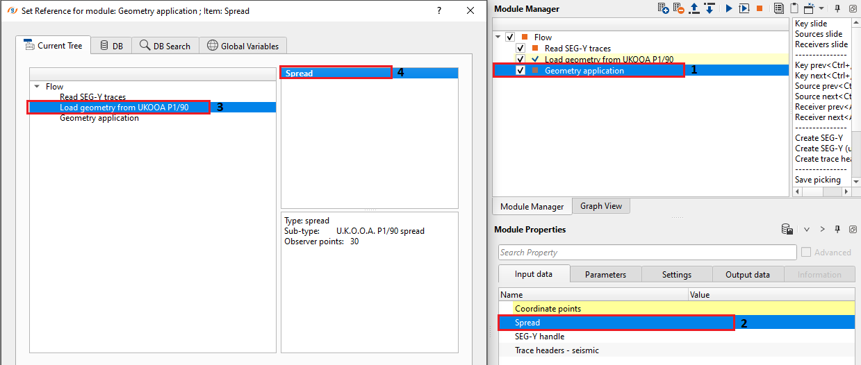
From the above images, "Geometry application" module connects/references the Coordinate points and Spread information from "Load geometry from UKOOA P1/90" module. Similarly, SEG-Y handle and trace headers - seismic will be taken from "Read SEG-Y traces" module.
![]()
![]()
YouTube video lesson, click here to open [VIDEO IN PROCESS...]
![]()
![]()
Yilmaz. O., 1987, Seismic data processing: Society of Exploration Geophysicist
 * * * If you have any questions, please send an e-mail to: support@geomage.com * * *