Muting the noise above the first arrivals by using water bottom
![]()
![]()
Marine seismic data is considered less noisy compared to the onshore/land seismic data . During the onshore seismic data acquisition, there are various factors influence the data quality. In onshore data, we observe the power lines noise, vehicular noise, ground roll noise. These noises are so much that the signal to noise ratio is poor to very poor in some instances. On the other side, offshore seismic data acquisition is less noisy however it is also contaminated with swell noise, tug noise, streamer/cable noise etc. Irrespective of the environment, noise is common in both the acquisitions.
In offshore seismic data, we observe strong noise above the first arrivals. This could be due to the water column above the water bottom or sea condition which causes the swell noise. To attenuate/remove the noise above the first arrivals, we implement various schemes. One of them is Mute by Sea bottom. This module is used to mute the data anything above the first arrivals by using the source and receiver depths. Besides, it requires the replacement velocity and refraction velocity to compute the travel time values. Based on these first arrivals/breaks, it will mute the data above or below the first arrivals/breaks.
Mute by sea bottom module can be used to mute the direct arrivals or refracted energy for marine data. From the trace headers, we extract the Source Water Depth and create the source water depth index using “Create Interpolation Matrix” module and use this information to mute the direct arrivals or refracted energy.
![]()
![]()
Input DataItem
Input gather - If running inside the Seismic Loop module, input gather is automatically connected from the Seismic Loop module
![]()
![]()
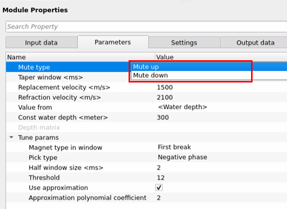
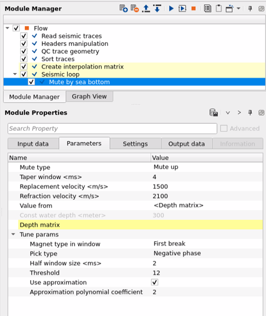
Mute type { Mute up, Mute down } - Specify the kind of mute to be applied.
Mute Up - Mutes the data above the source water depth index
Mute Down - Mutes the data below the source water depth index
Taper window - this parameter avoids any sharp boundaries at the boundary. Taper window helps smooth transitioning of the data at the mute boundary.
Replacement velocity - Define the water velocity or near surface velocity in m/sec.
Refraction velocity - This refraction velocity parameters helps in calculating the first arrival travel times. Define the refraction velocity.
Value from { <Water depth>, <Depth matrix> } - This parameter section deals with the water depths. The user needs to specify from where the source and receiver depths are accessed.
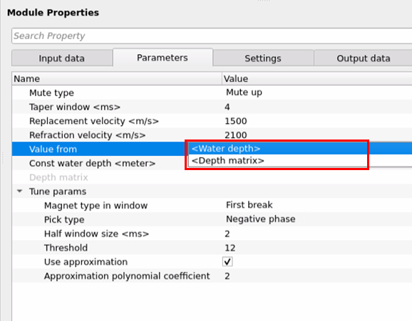
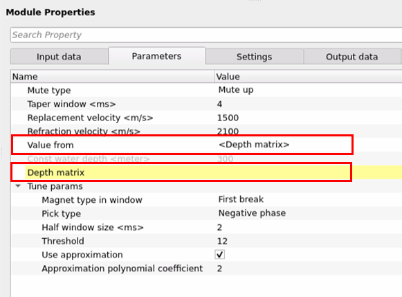
ValueFrom - <Depth matrix> - If the Value from Depth matrix, then the user should provide the source & receiver depths.
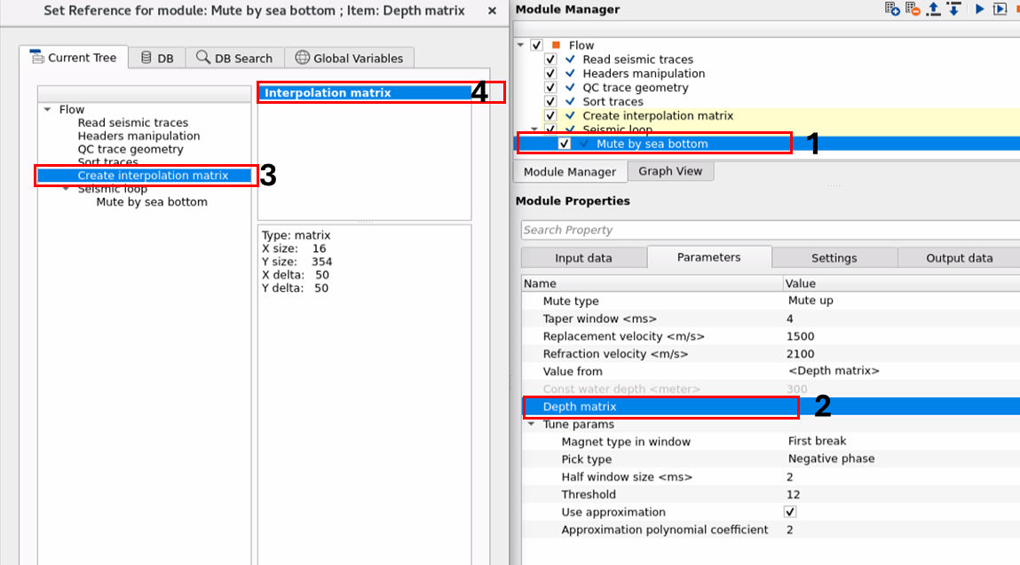
Depth matrix - Connect/reference the Interpolation matrix output from the "Create interpolation matrix" module.
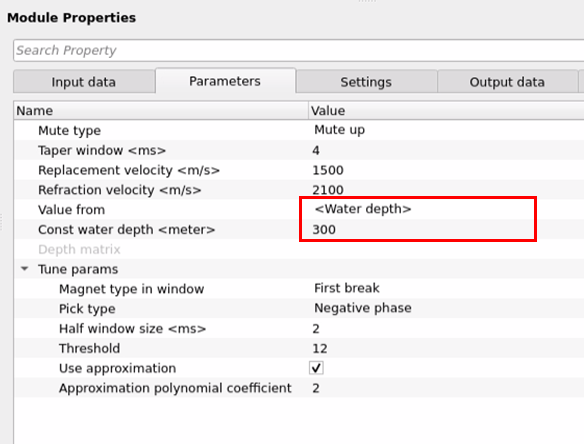
ValueFrom - <Water depth> - If the value from Water depth, the user should specify the source & receiver depths.
Const water depth - Provide the constant water depth value. By default, 300 meters.
Tune params - In this parameter section, it will work on fine tuning of the mute based on the refraction and replacement velocities.
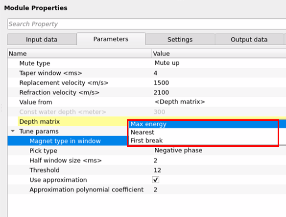
Magnet type in window { Max energy, Nearest, First break } - There are 3 types of Magnets available.
Max energy - This is nothing but the maximum/peak amplitude of the seismic trace. The maximum amplitude exists at the first arrivals/breaks. This criteria is used to mute the data anything above or below of the maximum energy of the seismic trace.
Nearest - This is related to the nearest refraction time arrival time from the water bottom interference.
First break - This parameter is related to the seismic signal arrival at the receiver. This is usually the refractions. When the source is fired, it will travels first, refracts and finally received at the receiver. This is what we call as first arrival/break. This is the most preferred method to attenuate the noise anything above the first arrivals/break.
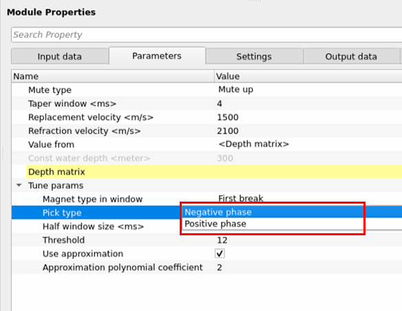
Pick type { Negative phase, Positive phase } - Choose the appropriate phase to pick/identify the first breaks/arrivals.
Negative phase - This is the negative part of the seismic trace. Also known as trough.
Positive phase - This is the positive side of the seismic trace. Also known as peak.
Half window size - This parameter refers to the size of the window around a selected point in the seismic trace where the muting function is applied. Half window means, it will consider only one side of the selected point of the seismic trace where as the full window considers the full which applies symmetrically. If the half window size is large, it will apply the muting wide range of the seismic data around the specified first breaks/arrivals. If the half window size is small, it will apply the muting in smaller region of the seismic data.
Threshold - This parameter is used as a certain limit is used start the muting function. The limit can be amplitude, travel time or travel distance between source and receiver i.e. offset.
In case of the amplitude, based on the maximum peak amplitude, it will start the muting. Similarly, if the travel time exceeds certain limit then the muting takes place.
Use approximation - Select this option to calculate the travel time of the seismic waves by using the polynomial approximation. By default, it is unchecked.
Approximation polynomial coefficient - this coefficient is used to determine the shape of the wavelet that best fits the travel time data while calculating the source-receiver travel times or travel distance by using the polynomial approximations.
![]()
![]()
Auto-connection - By default, Checked (Yes).
Bad data values option { Fix, Notify, Continue } - This is applicable whenever there is a bad value or NaN (Not a Number) in the data. By default Notify. While testing, it is good to opt as Notify option. Once we understand the root cause of it, the user can either choose the option Fix or Continue. In this way, the job won't stop/fail during the production
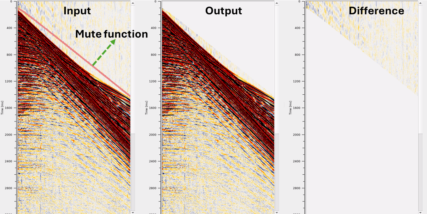
Calculate difference - This option creates the difference display gather between input and output gathers. By default Unchecked. To create a difference, check the option.
Number of threads - One less than total no of nodes/threads to execute a job in multi-thread mode.
Skip - By default, No (Unchecked). This option helps to bypass the module from the workflow.
![]()
![]()
Output DataItem
Output gather - Outputs the muted output gather
Gather of difference - Generates the difference between the input and output gather.
![]()
![]()
In this example workflow, we are reading the geometry assigned gathers with source and receiver depths are stored in the trace headers. In case, the depths are not available, the user can update these manually by using "Headers manipulation" module.
To check whether the source and receiver depths are available in the trace headers, the user can use "QC trace geometry" module to generate the QC plots and confirm the existence of the depth values.
By choosing the Value from parameter "Depth matrix", we need to connect/reference the Depth matrix to Interpolation matrix of "Create interpolation matrix"
Adjust the replacement velocity, refraction velocity, half window size etc and execute the module to check the results of the mute by sea bottom module. Here is an example shot gather before and after mute by sea bottom module.
![]()
![]()
There are no actions items for this module. So ignore it.
![]()
![]()
YouTube video lesson, click here to open [VIDEO IN PROCESS...]
![]()
![]()
Yilmaz. O., 1987, Seismic data processing: Society of Exploration Geophysicist
 * * * If you have any questions, please send an e-mail to: support@geomage.com * * *
![]()