Removing the Ghost effect in Tau-P Domain
![]()
![]()
Marine seismic data comprises of many noise components. Out of the many, ghosts are one of them. Ghosts are nothing but an unwanted seismic reflections which are recorded at both source and receiver side. When the seismic energy source (Airgun for marine data and dynamite or vibroseis for land data) is active, the energy penetrates through the layers of the earth. The waves are transmitted, reflected and refracted. These reflected sub surface waves are recorded at the surface (land & marine) by Geophones and hydrophones respectively. Some of these reflected waves are bounced at the surface (land & water). In case of the marine it is quite evident. These reflected waves have an extra travel time (traveling of the up going wave towards the water surface and return back and recorded at the receivers so as at the source end.) since the source and receivers are towed below the sea surface. These waves take extra time to travel at both source and receiver side. This will create side lobes on the wavelet. Each representing the source side ghost and receiver side ghost.
Due to the extra travel time, Ghost is also known as delayed primary. In marine acquisition, sea surface acts as a boundary. Due to impedance contrast (air and water boundary which gives rise to -1), the delayed primary or secondary reflections or ghosts have reverse polarity. Also, they posses lower amplitudes.
Ghost is an issue in marine data processing and it is important to remove or attenuate the ghost effect. It is important to note that the presence of Ghost makes the seismic data interpretation difficult. In the absence of ghost, the data looks more cleaner with less noise. Deghosting enhances the resolution of the data by reducing the ghost noise which gives rise to better resolution of the subtle geological features.
If we need to explain the ghost in simple way we can say Recorded Data = Primary + Source Ghost + Receiver Ghost
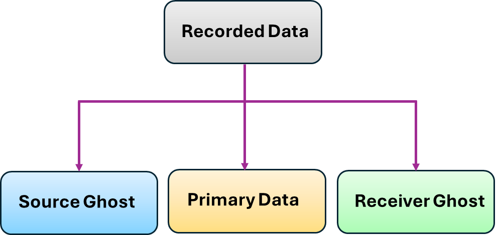
In order to get the ghost free data (Primary), we have to remove both source side ghost and receiver side ghost.
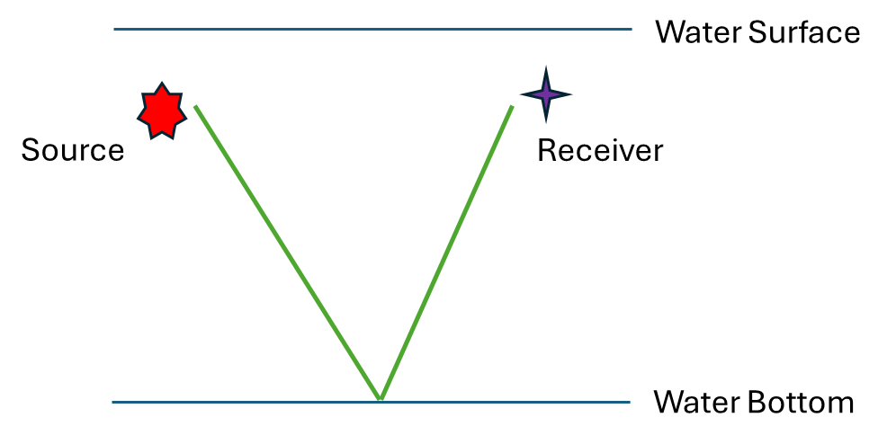
Figure 1. Schematic Diagram of Ghost free data
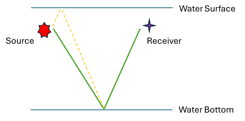
Figure 2. Schematic Diagram of Source Ghost
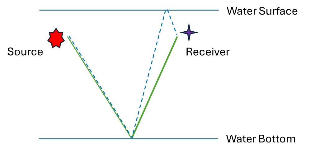
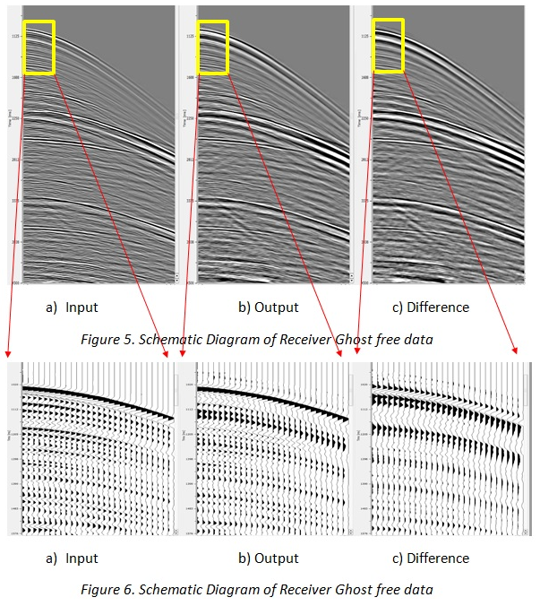
Figure 3. Schematic Diagram of Receiver Ghost
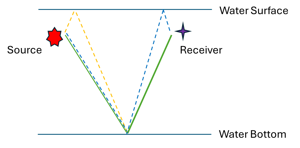
Figure 4. Schematic Diagram of Source and Receiver Ghost
Deghosting enhances the signal to noise ratio. And also boost the low frequency In the case of shallow data, the data looks higher frequency due to the removal of the side lobes. For deeper events, data looks like low frequency. There are two factors which influences this. One is due to the attenuation of energy and second one is of elimination of side lobes. Due to this data looks higher frequency in the deeper part of the section. Once we apply the Deghost filter then the data looks low frequency.
There are various methods to minimize the ghost. During the acquisition, we can lower the streamer to a bit deeper level to minimize the receiver ghost effect. Also we can use variable depth streamers to minimize receiver ghost effect. This works due to the notch diversity created by variation in the receiver depths.
In the case of data processing/imaging, we have different methods to attenuate ghosts. In g-Platform, we perform the Deghosting in Tau-P and F-K domain.
In Tau-P Deghost, we transform the t-x data into Tau P domain where as in the FK Deghost, we transform the t-x data into Frequency Wavenumber domain.
When preparing the input data for Deghosting, make sure that both source and receiver water depths are present in the trace headers. If not, then the user has to manually provide these values at the parametrization.
User recommendations:
To run the receiver deghosting, sort the data into FFID/Source_SP as Primary Key and Channel as Secondary key. The output will be Receiver ghost free data.
![]()
![]()
Input gather - Connect/reference to the Input gather. If it is inside the Seismic loop, it will automatically connects the output gather of the previous module to the input gather of "Tau-P Deghost" module.
![]()
![]()
Fast execution - By default, Unchecked (No). This is useful while testing the parameters for a faster turn around time.
Domain { Time, Frequency } - Select the options from the drop down menu. Tau-P Deghost can be performed in both Time and Frequency domain. In case of the time domain, the data transform from time-space domain to Tau-P domain. Whereas in the case of Frequency domain, the data transform from frequency-wavenumber to Tau-P domain.
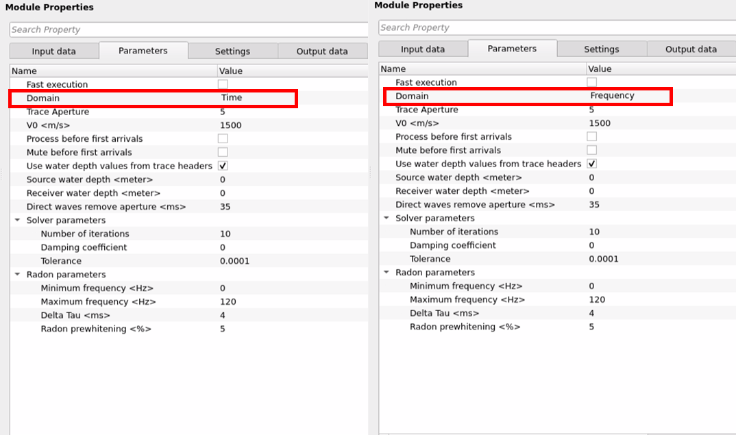
Trace Aperture - Provide the total number of traces participating to perform the Tau-P operation. If user provides 5 as trace aperture then there will be 2 traces on either side of it and the center trace will act as pilot trace. If more number of traces are used then the spatial extent of the data is better to better differentiate the primary and ghost reflections, however if the total number of traces are too low, there is less information about the ghost and primaries.
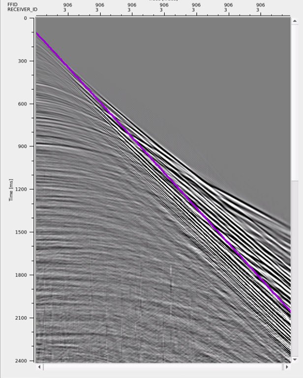
V0 - Provide the accurate water velocity. This V0 value draws a line on the shot gather. This will be used for muting direct arrivals.
Process before first arrivals - By default, Unchecked. This option gives the option to perform the muting of first arrivals. This parameter option works in tandem with the next parameter i.e. Mute before first arrivals.
Mute before first arrivals - By default, Unchecked. If this options checked, it will mute the data above the first arrivals.
Use water depth values from trace headers - If checked, it will read the source and receiver water depths information from the trace headers.
Input gather type { None, Common shot, Common receiver, Ambiguous } -
Source water depth - In case the source water depth is not present in the trace headers, provide the source water depth value.
Receiver water depth - Similar to the source water depth, provide the receiver(s) water depth if this information is not available in the trace headers.
Direct waves remove aperture - Define a value say 40ms and it will acts a taper zone. To mute the data above the direct wave arrivals, define a taper value. Anything above this line will be muted. Remember, the purple line is drawn based on the V0.
Solver parameters
Number of iterations - Define the number of iterations to perform in tau-p domain
Damping coefficient - This parameter make sure not to over doing of the deghosting. If the damping coefficient is too high, the filter will attenuate both the ghost and signal. If it is too low, it will not effectively attenuate the ghost. Careful parametrization is important for better results.
Tolerance - Define the tolerance value up to what extent (error) is acceptable for the better deghosting. After reaching the defined tolerance value, the deghosting process stops which indicates an acceptable deghosting has been achieved.
Radon parameters
Minimum frequency - Provide the minimum frequency used for radon transformation
Maximum frequency - Provide the maximum frequency used for radon transformation
Delta Tau - In time domain, we provide the sample interval. Similarly in Tau domain, we need to provide the step size. Provide the step size of delta tau to perform the deghosting in tau-p domain. The lesser the Tau value the better resolution however it will increase the computation time.
Radon prewhitening - Specify the Prewhitening noise percentage applied to the data to stabilize the result
![]()
![]()
Auto-connection - By default Yes (Checked)
Bad data values option { Fix, Notify, Continue } - This is applicable whenever there is a bad value or NaN (Not a Number) in the data. By default Notify. While testing, it is good to opt as Notify option. Once we understand the root cause of it, the user can either choose the option Fix or Continue. In this way, the job won't stop/fail during the production
Number of threads - One less than total no of nodes/threads to execute a job in multi-thread mode.
Skip - By default, No (Unchecked). This option helps to bypass the module from the workflow.
![]()
![]()
Output gather - This module outputs ghost free output gathers
![]()
![]()
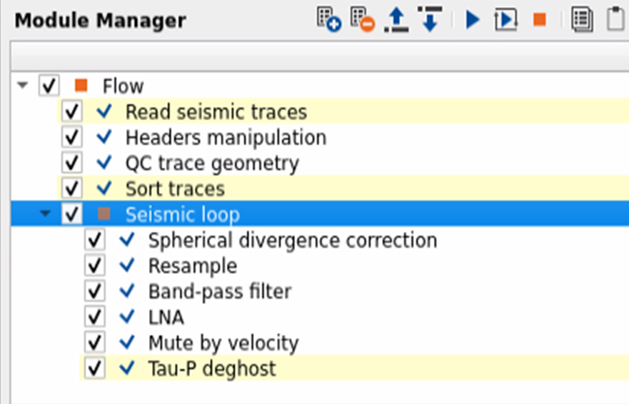
This is an example workflow just to show how to build the workflow.
1. Read the internal dataset using "Read seismic traces".
2. Headers manipulation - If the input doesn't have source and receiver water depths then we can use this module to assign the values.
3. QC trace geometry - This is optional. We've used this module to QC the source and receiver water depths.
4. Sort traces - Sorted the data in FFID-Receiver_ID as Grouping and OFFSET as Sorting.
5. Inside the Seismic loop, we've added few processing modules. As we mentioned earlier, if the input data is denoise gathers then these modules aren't necessary.
![]() We've taken the geometry assigned gathers and added spherical divergence correction, resample, band pass, LNA, mute by velocity (to mute anything above the first arrivals) modules to the workflow to do a basic processing before doing the Tau-P Deghost. If the input data is denoise gathers then the user can directly use the Tau-P Deghost module.
We've taken the geometry assigned gathers and added spherical divergence correction, resample, band pass, LNA, mute by velocity (to mute anything above the first arrivals) modules to the workflow to do a basic processing before doing the Tau-P Deghost. If the input data is denoise gathers then the user can directly use the Tau-P Deghost module.
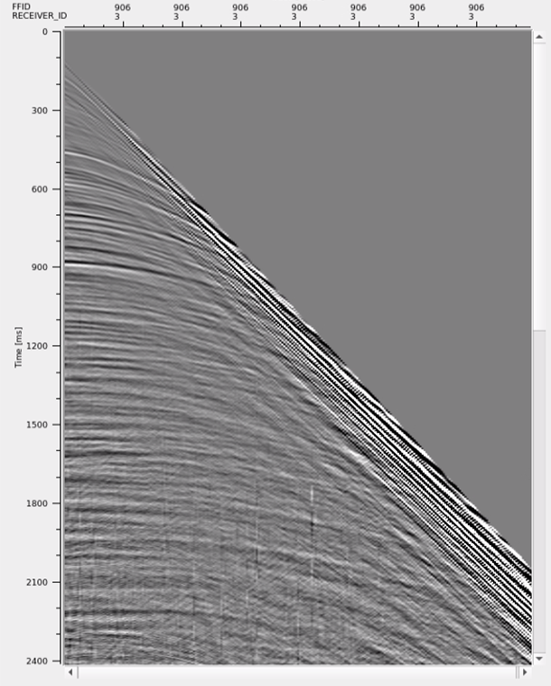
In this example, we are showing a shot gather before and after deghosting
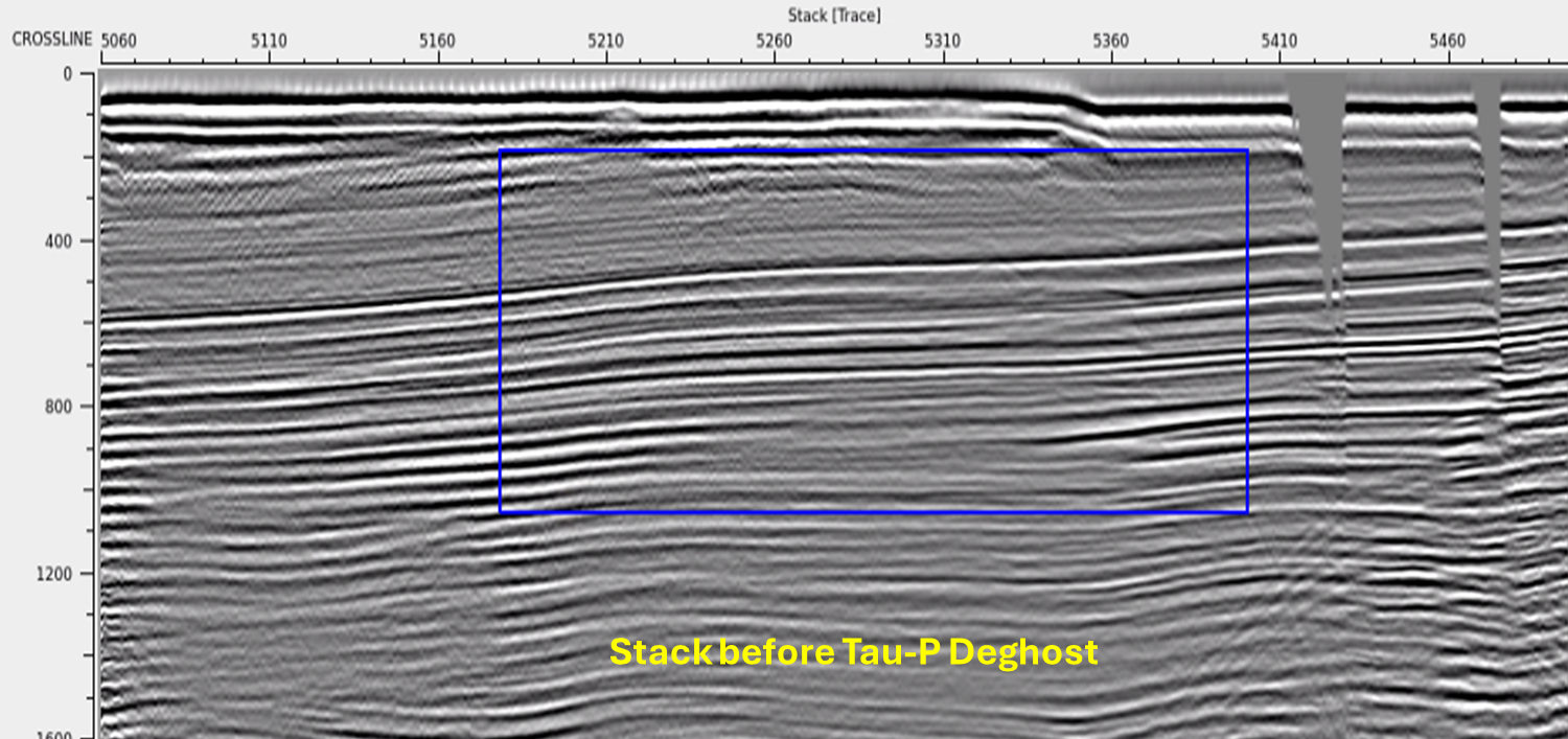
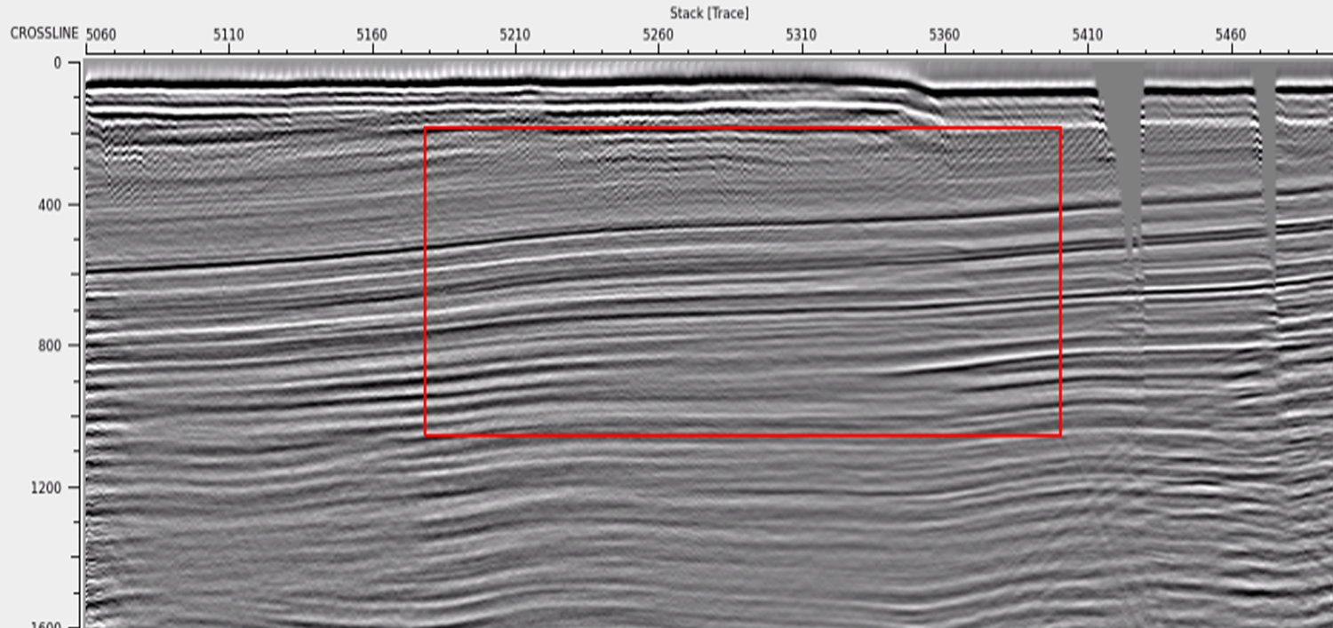
Stack response before and after Tau-P Deghost
![]()
![]()
YouTube video lesson, click here to open [VIDEO IN PROCESS...]
![]()
![]()
Yilmaz. O., 1987, Seismic data processing: Society of Exploration Geophysicist
 * * * If you have any questions, please send an e-mail to: support@geomage.com * * *