Horizon picking
![]()
![]()
Horizon picking module helpful in picking the water bottom in marine seismic surveys. Also, it is used to pick any other horizons for interpretation or velocity model building.
The Horizon Picking module enables interactive and automated picking of seismic horizons directly on stack sections displayed in the Vista viewer. Users can pick reflectors manually by clicking on the seismic section, or use the automatic picking engine to propagate picks along a reflector. Multiple independent horizons (layers) can be picked simultaneously, each identified by a numeric index. After picking, the module spatially interpolates all picks across the survey grid and outputs the resulting horizon as a PostStack Horizon item, an Output Horizons item for ASCII export, and a tabular Horizon Picks Table. This module is commonly used for water-bottom picking in marine surveys, surface definition for static corrections in land surveys, and horizon extraction for depth model building.
How to pick the horizon?
1. Choose any random bin point on the "Location map"

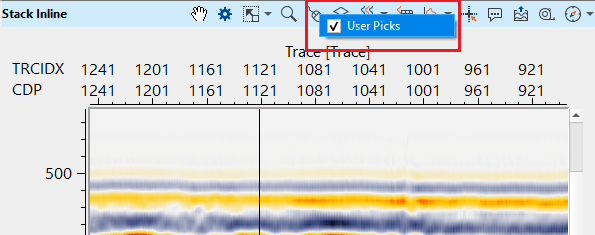
2. Go to Stack inline/Crossline. Check "User picks" option is checked inside the control item ![]() .
.
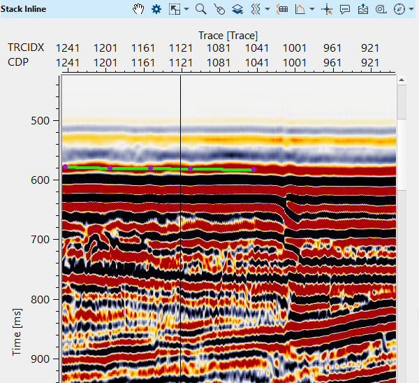
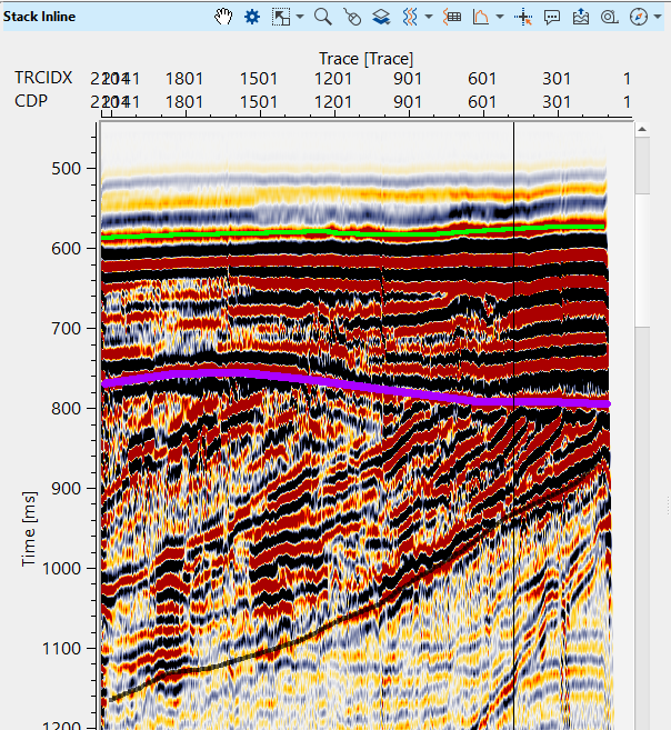
3. Choose the desired horizon and start clicking on the reflector (a purple point starts appearing along with green points).
4.After completed picking, hold ALT+MB3 (RMB). It gives various options to choose from

To update the horizon, select update layer. It will update the horizon/layer in the location map.
To convert filled points as horizon, click "Convert filled points". It will appear as horizon (purple line).

To create a new horizon/layer, click on "Create new layer."
![]()
![]()
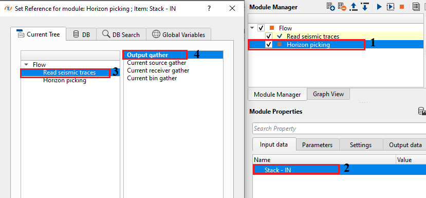
Stack - IN - input should be a stack section. Connect/reference the output gather from Read seismic traces module or any other module which generates Stack as Output gather or vista item like Stack Imaging module.
![]()
![]()
Replacement velocity - - specify the replacement. It is useful in case of the onshore data where the horizon should be in connection with the datum.
The replacement velocity (in m/s) is used internally to apply a datum shift to the displayed stack section before picking. When a non-zero Datum is set, the module shifts the seismic data by the time equivalent of the datum elevation at the replacement velocity, so that horizon picks are correctly referenced to the processing datum. The default value is 2000 m/s, which is a typical near-surface velocity. For marine surveys where the Datum is 0, this value has no effect. For land surveys, set this to the representative near-surface or replacement velocity used in your static corrections workflow.
Datum - specify the datum value. By default, 0. In case of marine data, it is zero. For onshore data, the user should mention the datum value prior picking the horizon.
The datum defines the reference elevation (in the same units as your survey — typically metres) to which the horizon picks will be tied. The default value is 0, which is correct for marine surveys where sea level is the datum. For land surveys, enter the processing datum elevation used during your statics correction workflow. Setting the correct datum ensures that picked horizon times are accurately referenced, and that any datum-shift correction applied to the displayed section matches the one used in processing. Set this parameter before you begin picking.
Current horizon - this shows the current horizon name. By default, 0. The user can change this value to any user desired value.
This integer index (starting at 0) selects which horizon layer is currently active for picking and display. All manual clicks and automatic picking actions apply to the horizon with this index. To work on a different horizon, change this value before picking. Use the Create horizon custom action to add a new layer, and then increment this index to switch to it. The module prevents the index from going below 0 or above the total number of created horizons minus one.
Manual picking params - this section deals with the manual picking parameters for horizon picking.
This group of parameters controls how individual horizon picks are made and how the auto-picking propagation engine behaves. Adjust these settings to match the reflector character and signal-to-noise ratio of your dataset before beginning any picking session.
Manual picking window - within the user specified time window, manual picks will happen.
Defines the time half-window (in seconds) around the user's click point within which the picking algorithm searches for the peak or zero-crossing of the target phase. The default is 0.02 s (20 ms). A narrower window gives more precise picks on a clean reflector; increase this value when the reflector is less distinct or the seismic data has low frequency content.
Automatic picking window - specify the automatic picking time window.
Defines the search window used by the automatic picking propagation engine when extending picks from a seed pick to adjacent traces. The default is 6 s, which effectively covers the entire typical seismic record depth. Reduce this value when working with a shallow, well-constrained reflector to prevent the autopicker from jumping to nearby interfering events.
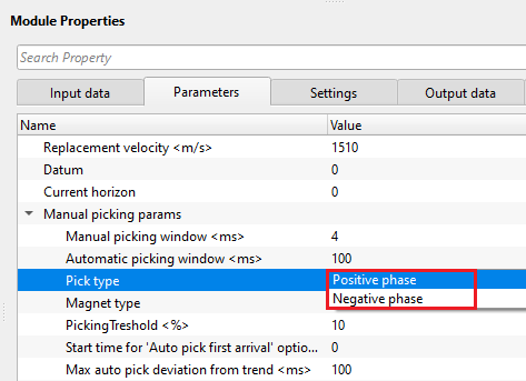
Pick type { Positive phase, Negative phase } - specify the picking phase. Select the phase type from drop down menu.
Selects which polarity of the reflector amplitude peak to snap picks to. Choose Positive phase to pick at a positive amplitude peak (typically displayed as a red or black trough depending on display convention), or Negative phase for a negative amplitude peak. The choice depends on the polarity convention of your data and which peak best delineates the target horizon. The water bottom in zero-phase normal-polarity data typically appears as a positive peak.
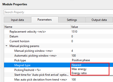
Magnet type { Nearest, Max energy, Energy ratio } - this option allows the user to select the magnet type to pick the horizon. This is one of the criterion to pick the horizons based on the type of the magnet. By default, Nearest.
Controls how picks are snapped to the reflector within the picking window. Three modes are available:
Nearest — the pick is placed at the sample closest in time to the user's click point, within the picking window. This is the simplest and fastest mode, suitable when the reflector is clearly visible and the click is close to the target.
Max energy — the pick is placed at the sample of maximum absolute amplitude within the window. This mode is best when picking a strong, laterally continuous reflector and the user wants picks to always snap to the amplitude peak regardless of click precision.
Energy ratio — picks are guided by the ratio of signal energy above and below the candidate sample. This criterion detects reflector interfaces more robustly in noisy data or when multiple closely spaced events are present, as it seeks samples where the energy contrast is highest rather than just the amplitude peak.
Nearest - this option picks the horizon nearest to the user selected point.
Max energy - this option picks the horizon where the maximum velocity semblance or energy exists.
Energy ratio - it is the ratio of minimum and maximum energy of the sample and based on it's value it picks the horizon.
PickingTreshold - this parameter controls the quality of the picks. Depending on the user specified threshold value, horizon picks may be good or bad. Below the user specified picking threshold value, it rejects the pick and moves to the next location.
A quality gate applied during automatic picking. The value ranges from 0.0 to 1.0, with the default set to 0.5. The autopicker evaluates the quality of each candidate pick relative to the maximum amplitude within the window. If the candidate quality score falls below this threshold, the pick is rejected for that trace and the auto-pick does not generate a value at that location. Lower values (closer to 0) accept more picks, including weak or uncertain ones. Higher values (closer to 1) accept only high-confidence picks on strong reflectors. Use a higher threshold on noisy data to avoid false picks, and a lower threshold on good-quality reflectors where continuity is the priority.
Start time for 'Auto pick first arrival' option - define the starting time to pick the first arrivals. By default, 0 ms.
Used exclusively by the Auto pick first arrival custom action. This parameter specifies the earliest time (in seconds) from which the first-arrival autopicker will begin searching for the onset of energy on each trace. The default is 0 s, meaning the search starts from the very beginning of the record. If the data has a predictable mute zone or noise before the expected first break, set this value to skip past it and improve picking accuracy.
Max auto pick deviation from trend - define the maximum acceptable auto pick deviation from the trend.
During automatic picking propagation, the engine computes a running trend through previously accepted picks. This parameter (in seconds) limits how far a new candidate pick can deviate from that trend before being rejected. The default is 6 s, which effectively disables the trend constraint. Set a tighter value (e.g., 0.02–0.1 s) to prevent the autopicker from jumping to a different reflector or noise spike on adjacent traces, particularly when the target horizon has gentle dip and the seismic quality is good. Use the default value for highly dipping or irregular horizons where large trace-to-trace time variations are expected.
Map interpolation - it performs the interpolation of the picked horizons and creates a map.
After picks are made on individual inlines and crosslines, the module spatially interpolates them across the survey area to generate a continuous horizon map. This map is displayed on the Location Map and is the basis for the PostStack Horizon output item. The parameters below control the resolution and coverage of the interpolation grid.
interpolation Step X - specify the interpolation step size in X - direction. By default, 200
The lateral grid spacing (in metres) used for horizon interpolation in the X direction (inline direction or Easting). The default is 200 m. Smaller values produce a finer interpolation grid and a smoother horizon map at the cost of increased computation time. Set this value to match the typical bin spacing of your survey in the X direction for best results.
interpolation Step Y - specify the interpolation step size in Y - direction. By default, 200
The lateral grid spacing (in metres) used for horizon interpolation in the Y direction (crossline direction or Northing). The default is 200 m. Set this to the typical bin spacing of your survey in the Y direction. For surveys with non-square bins (e.g., 25 m inline by 50 m crossline), adjust Step X and Step Y independently to match the acquisition geometry.
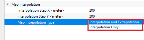
Map intrepolation Type { Interpolation and Extrapolation, Interpolation Only } - select the interpolation from the drop down menu.
Interpolation and Extrapolation — fills the horizon time values both between picked points (interpolation) and beyond the outermost picks at the survey edges (extrapolation). Use this option to ensure a complete horizon map with no gaps at the survey boundary. This is the default mode and is suitable for most workflows.
Interpolation only — fills horizon values only within the region bounded by actual picks, leaving areas beyond the outermost picks empty. Use this mode when you want to avoid generating speculative horizon values in areas without data coverage.
Interpolation and Extrapolation - it performs both the interpolation and extrapolation between and beyond the picked points.
Interpolation only - it performs only interpolation between the picked points.
![]()
![]()
Auto-connection - By default, TRUE(Checked). It will automatically connect to the next module. To avoid auto-connect, the user should uncheck this option.
When enabled, the module automatically passes its output data to the next connected module in the workflow upon execution. Disable this option if you want to run the Horizon Picking module interactively in isolation — for example, when performing picking and interpolation without immediately triggering downstream processing steps.
Number of threads - One less than total no of nodes/threads to execute a job in multi-thread mode. Limit number of threads on main machine.
Sets the maximum number of CPU threads the module may use. The Horizon Picking module supports multi-threaded execution (flagged EPROCEDURE_DETAILS_MT in the source). Set this to a value appropriate for your workstation — typically the number of physical CPU cores minus one, to leave resources available for the operating system and GUI.
Skip - By default, FALSE(Unchecked). This option helps to bypass the module from the workflow.
When checked, the module is skipped during workflow execution and its outputs are not updated. Data passes through unchanged. Use this to temporarily disable the Horizon Picking step without removing it from the workflow.
![]()
![]()
Stack inline - generates stack inline as a vista item. It is also used for a connection/reference.
A vista item displaying the inline section through the currently selected bin point. The inline section is corrected to datum using the Replacement velocity and Datum parameters before display. Use this item to navigate the inline view and pick horizon points on the selected inline.
Stack crossline - generates cross line stack as a vista item.
A vista item displaying the crossline section through the currently selected bin point, also corrected to datum. Together with the Stack inline, this provides two orthogonal views of the 3D dataset at the selected location. For 2D surveys, only the inline view is relevant.
PostStack Horizon - generates poststack horizon. This horizon can be exported.
A point vector item containing the spatially interpolated horizon map for the currently selected horizon layer. This item can be connected to downstream modules (such as Mute by sea bottom or depth modeling workflows) or exported for use in other applications. The values represent two-way travel times in seconds at each interpolated grid node.
Output horizons - generates the output horizons. These horizons can be exported as ASCII files.
A horizon picking item containing all picked and interpolated horizon layers. This item stores the full multi-horizon dataset and supports export to ASCII format (using the Export picking custom action or an export module). Use this output to transfer horizon picks to third-party interpretation software or archive the picking results.
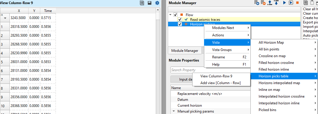
Horizon picks table - generates the horizon picks table. These tables can be exported by using Export table module.
A tabular output listing the individual pick data — bin coordinates (X, Y), two-way time, and horizon index — for all accepted picks in the current session. Open this table in the Vista viewer using the Fill horizon picks table custom action, and export it to ASCII using the Export table module for QC or further analysis.
The Settings section contains standard execution settings shared by all g-Platform modules, such as the number of processing threads, auto-connection behavior, and the skip flag. See the parameter descriptions below for details.
![]()
![]()
In this example workflow, we read a post-stack section using "Read seismic traces" module and Load data to RAM as YES.
After making necessary connections/references, adjust the parameters as per the input data requirements and start picking the horizons (as described in the theory part).
After picking the horizon, execute the module. It will generate the interpolated horizons in the Interpolation location map.
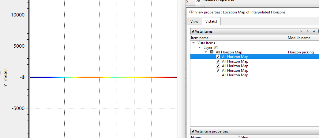
![]()
![]()
Clear all horizons - this option let the user to clear all the existing horizons.
Removes all picks from every horizon layer in the current session. Use this action to start picking from scratch. This action is irreversible within the current session — make sure to export your picks first if you need to preserve the current results.
Clear current horizon - this clears the current horizon.
Removes all picks from the horizon layer currently selected by the Current horizon parameter, while leaving all other horizon layers intact. Use this action to re-pick a specific horizon without losing work on others.
Create horizon - this allows the user to create a new horizon by clicking this option.
Adds a new empty horizon layer. After clicking this action, increment the Current horizon index to the new layer and begin picking on it. This workflow allows you to pick multiple independent horizons (e.g., water bottom, multiple reflectors for velocity model building) in a single module instance.
Export picking - picked horizons can be exported as an horizon file. It saves the horizon with ".hor" extension
Saves all current horizon picks to a binary file with the .hor extension. This file preserves the complete picking session and can later be reloaded using Import picking. Use this action regularly to save progress during long picking sessions and before closing the project.
Import picking - - this option allows the user to import the horizons.
Loads previously exported horizon picks from a .hor file. This allows picking sessions to be resumed, merged, or shared between users. After import, the loaded picks are immediately visible on the seismic section and the location map.
Interpolate horizons - it interpolates the picked horizons in between the picked points.
Triggers spatial interpolation of the current picks to fill the horizon map between and (optionally) beyond the picked bin locations, using the Step X, Step Y, and Map interpolation type parameters. Run this action after adding or updating picks to refresh the interpolated horizon map in the Location Map view and to update the PostStack Horizon output item.
Auto pick first arrival - automatically picks the first arrivals.
Runs the automated first-arrival picker across all traces in the dataset, starting from the time specified by the Start time for 'Auto pick first arrival' option parameter. The picker looks for the first significant energy onset on each trace. This action is primarily useful for picking the water bottom in marine surveys, or for generating an initial first-break horizon on post-stack data that can then be manually edited. The Picking threshold and Max auto pick deviation from trend parameters govern pick quality and trend stability during this operation.
Fill horizon picks table - fills the horizon picks table. Launch Vista and select Horizon picks table and add view.
Populates the Horizon picks table output item with the current pick data. Once populated, open the Vista viewer, select the Horizon picks table item, and choose Add view to display the table. The table lists each pick's bin coordinates, horizon index, and two-way time. Export it to ASCII using the Export table module for QC reports or external processing.
![]()
![]()
YouTube video lesson, click here to open [VIDEO IN PROCESS...]
![]()
![]()
Yilmaz. O., 1987, Seismic data processing: Society of Exploration Geophysicist
 * * * If you have any questions, please send an e-mail to: support@geomage.com * * *