Horizontal Velocity Analysis Stack Imaging
![]()
![]()
Horizontal Velocity Analysis (HVA) is used to calculate the velocities accurately at the given CDP location along the picked horizon. This is very useful if you have the horizons information already. In order to avoid the long time taken for running the HVA Stack Imaging, we can precompute the Storage for the whole dataset so that it will be easier in the later stages. To precompute velocity analysis, use "Stack Imaging" module and specify the Precompute storage file name. Design the velocity parameters in the Velocity analysis parameters section and click "Precompute storage" in the action items. Check the progress bar to see whether the precomputing is running or not.
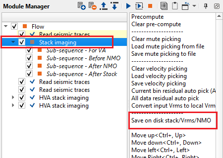
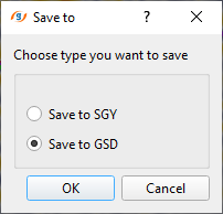
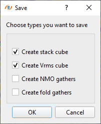
For HVA Stack Imaging, we require prestack data along with the stack and velocity volumes as Input Stack & Input VRMS. For 2D lines, the user can connect/reference the input stack and input Vrms from the Stack Imaging. If the stack and velocities are already available then use "Read seismic traces" module and "Load data to RAM" as YES. For 3D dataset, we MUST have the Inline Stack & Inline VRMS volumes ready. To generate Inline Stack & Inline VRMS, use Stack Imaging and click on "Save on disk stack/Vrms/NMO". Select "Save to GSD" and click OK. In the next window, choose the desired outputs like "Create stack cube" & "Create Vrms cube". Give it a name and it will save both the files in the internal format.
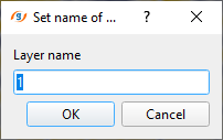
To create horizon in HVA, go to reference inline/crossline and Hold ALT+RMB or MB3. A panel appears.
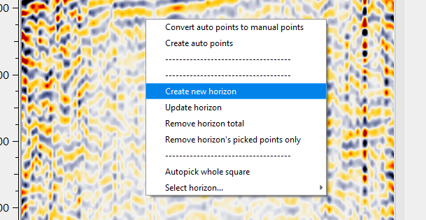
By default, starting horizon name appears as Layer__0 in the parameters. To create a new horizon, give it a name. It can be either a string or an integer.
In HVA stack imaging, is also useful to pick the water bottom horizon which is the input horizon for running the SRMP. To pick the water bottom horizon in HVA Stack Imaging launch Vista Groups and select any bin point location on the location map and start picking the water bottom horizon on the reference stack inline. Once done with the horizon picking, click the middle mouse button to interpolate the horizon. Next make approximate picks of water velocity on the Horizontal Semblance Inline Window. To complete this procedure, click ALT+Right Mouse Button to “ Update Velocity Semblance Horizon” inside the Horizontal Semblance Inline Window. Save the picked horizons under HVA Stack Imaging in “ Save horizons binary”.
In HVA Stack Imaging, sub-sequence procedures exist. These sub-sequence helps to avoid creating a separate workflow to apply an AGC or Deconvolution or other processing modules, we just simply insert those modules in the sub-sequence inside the main module. Put modules inside the sub-sequence as shown below:
•Sub-sequence - For VA: processing for velocity analysis, i.e. apply some procedures like band-pass or AGC, and then velocity spectrum is calculated;
•Sub-sequence - Before NMO: processing before applying NMO corrections to gathers, for example we can apply static corrections, AGC, band-pass filters etc,;
•Sub-sequence - After NMO: processing before applying NMO corrections to gathers, for example we can apply denoise procedures, AGC, band-pass filters etc.;
•Sub-sequence - After Stack: processing after stacking CMP gathers, for example we can apply denoise procedures or spectrum balancing.
•Sub-sequence - For Auto picking: processing for auto picking, for example we can apply band-pass filters, AGC etc.
![]()
![]()
Precompute storage - provide previously calculated precomputed storage file. This storage file stores all the velocity semblance information and it takes sometime to calculate it on the fly. Instead of performing the task on the file, it can be precomputed in Stack Imaging module. It is NOT mandatory. In case precompute storage file is not available, velocity semblance is calculated from the user defined velocity parameters.
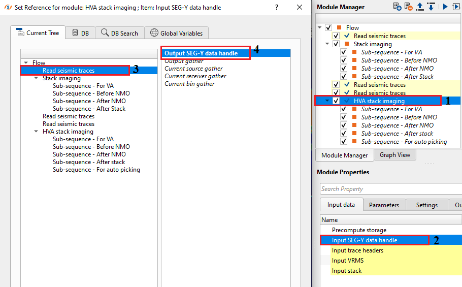
Input SEG-Y data handle - connect/reference to the Output SEG-Y data handle. It is used for getting the CMP/CDP gathers.
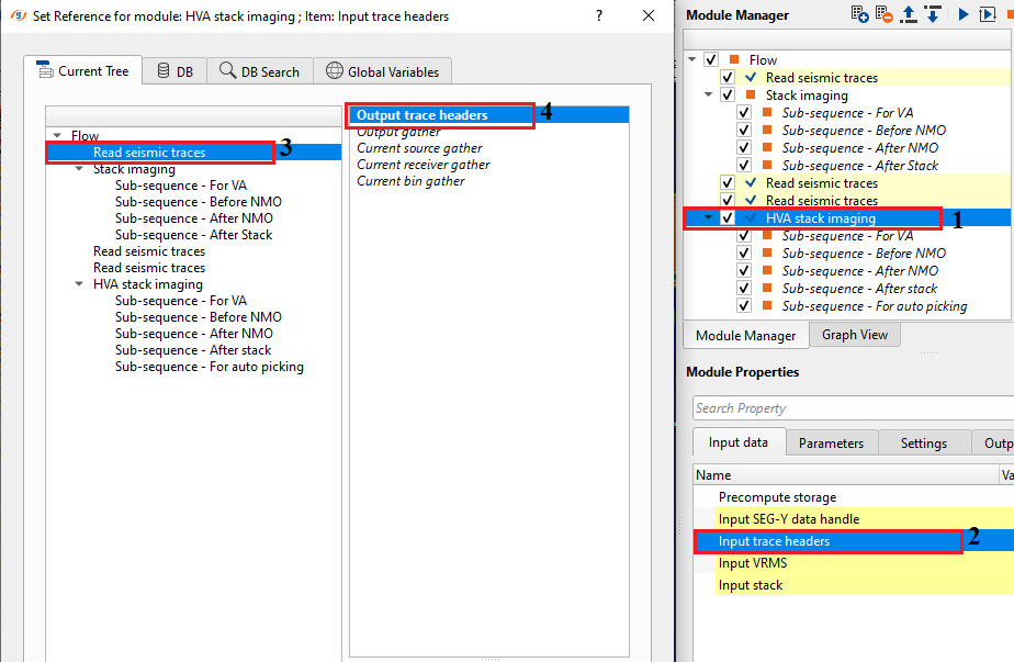
Input trace headers - connect/reference to Output trace headers. From the trace headers, it gets all the geometry information.
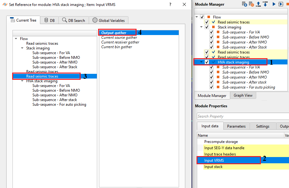
Input VRMS - provide Input RMS velocity file. It can be referenced/connected either by using "Read seismic traces" or Stack Imaging module. This is used as a reference velocity.
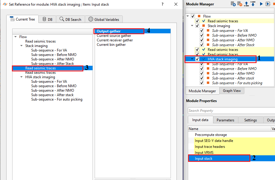
Input stack - provide input stack. Connect/reference to either Stack Imaging Input inline stack or Output gather from Read seismic traces module. This stack is used as a reference stack for horizontal velocity analysis.
![]()
![]()
HV to VV time window - this parameter is used to control the velocity smoothing when it is Horizontally Variable (HV) and also Vertically Variable (VV) by defining a time window. Within the user specified time window, it averages the velocities for each time sample. If the time window is small, it preserves the sharp velocity contrasts especially complex geologies like salt boundaries etc. If the time window is big, it over smooths the velocities and miss the finer details of the geology.
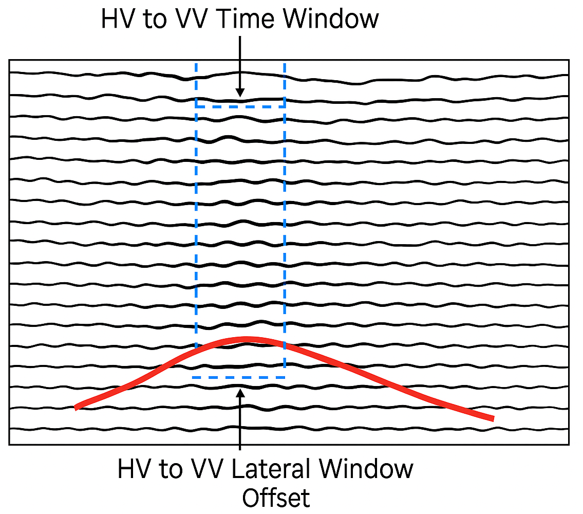
HV to VV lateral window - a horizontal velocity smoothing is applied to the neighboring traces to ensure smooth velocity field. It averages the adjacent traces (CMPs) and applies the smoother. Higher values may over smooth it and lateral velocity varies may not visible.
Interpolate between horizons - interpolates the picked values between the horizons. By default, FALSE.
Replacement velocity - Specify the replacement or near surface velocity value for datum shift.Set this value prior to beginning of the velocity picking.
Datum - we should provide the Datum value to shift the data from current datum to the final datum. By default, 0 meters.
Set velocity from VRMS on pick horizons - By default, TRUE (Checked). This option assigns the velocity from VRMS velocity which we provided at the Input VRMS at the Input data tab.
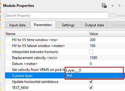
Current layer { Layer___0 } - this displays the current horizon. By default, Layer__0. If the user creates a new horizon, it will generates a new layer name as Layer__1
Update horizontal semblance - by default, TRUE (Checked). It updates the horizon semblance upon execution of the module.
TEST_NEW - By default, TRUE (Checked).
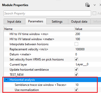
Horizontal analysis - this section deals with the horizontal velocity semblance calculation.
Semblance trace size window - specify the number of traces to be considered in the semblance calculation.
Use normalization - normalization helps in improving the picking. Without normalization, higher amplitude events masks the lower amplitude events and it may ignore/skip during the horizon picking.
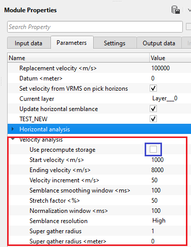
Velocity analysis - This is the main component of creating the semblance display. Inside the Velocity analysis, the user should define various parameters to generate the semblance, Common Offset (CO) gather, NMO stretch factor etc.
Use precompute storage - By default, YES(Checked). If this option is checked, it MUST be mandatory to provide the Precompute storage file at the Input data tab. Otherwise, it will calculate the semblance based on the parameters provided by the user.
Start velocity - Define the starting velocity value for creating the semblance. By default, 1000 m/s
Ending velocity - Define the ending velocity value for creating the semblance. By default, 6000 m/s
Velocity increment - Specify the the velocity increment step size. By default 50 m/s.
Semblance smoothing window - This value defines the smoothing of the semblance display. Higher window makes the semblance more smooth which is not ideal an ideal scenario but it depends on the input data quality. Default parameter value of 50ms works good.
Stretch factor - This parameter determines the NMO stretch factor. By default 50. If the user changes this value then the user can to observe the changes in the Velocity analysis window (Semblance display), Current NMO Seismogram display. Once the user executes the Stack Imaging module with the updated Stretch factor then the stack will be created using user defined NMO stretch factor.
Normalization window - Default 100 ms. This parameter is used for normalization of the semblance display.
Semblance resolution { High, Normal, Low } - Select the type of resolution. We have 3 options, Normal (By default), Low and High. By meaning of the Low and High, it decreases/increases the semblance resolution. Depending upon the input data quality the user can select the appropriate semblance resolution.
Super gather radius - define the super gather radius in meters.
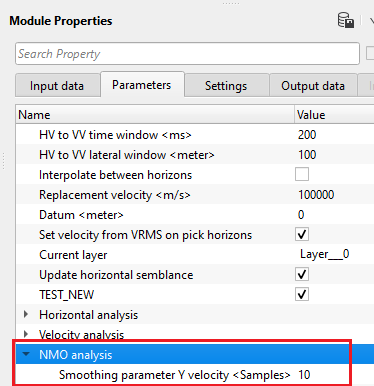
NMO analysis -
Smoothing parameter Y velocity - Default value is 10. Define the number of vertical samples to define the velocity smoothing.
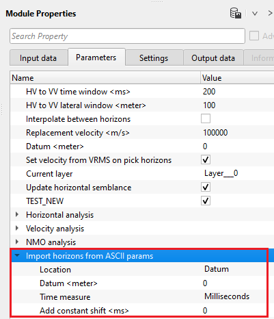
Import horizons from ASCII params - in case the horizons are imported, specify the required parameters.
Location { Datum, Topography } - choose the correct location of the picked horizon whether it is picked from datum or topography. In case of Datum, specify the datum value.
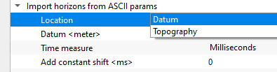
Datum - we should provide the Datum value to shift the data from current datum to the final datum. By default, 0 meters.
Time measure { Milliseconds, Seconds } - specify the time measurement of the imported horizons. By default,, milliseconds.
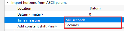
Add constant shift - specify a constant shift value in case the horizon needs to be shifted by a constant value. By default, 0.
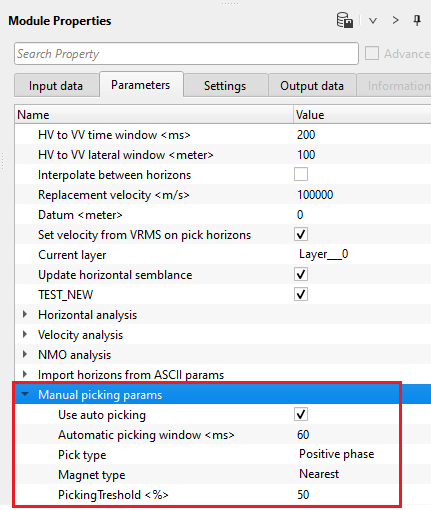
Manual picking params - this section deals with manual picking of the horizon. Set up the parameters for manual picking of horizons.
Use auto picking - By default, YES(Checked). It will automatically picks the horizon based on the automatic picking window and other parameters.
Automatic picking window - specify the horizon picking window.
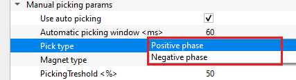
Pick type { Positive phase, Negative phase } - select either positive or negative phase to pick the horizon. By default, Positive.
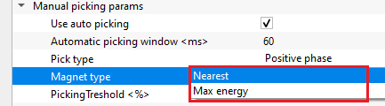
Magnet type { Nearest, Max energy } - this option allows the user to select the magnet type to pick the horizon. By default, Nearest.
Nearest - this option picks the horizon nearest to the user selected point.
Max energy - this option picks the horizon where the maximum velocity semblance or energy exists.
PickingTreshold - this parameter controls the quality of the picks. Depending on the user specified threshold value, horizon picks may be good or bad. Below the user specified picking threshold value, it rejects the pick and moves to the next location.
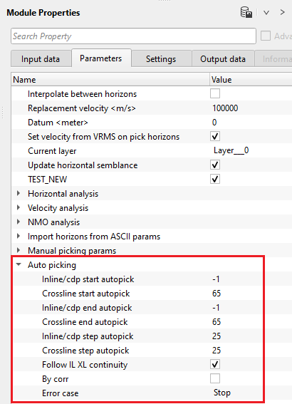
Auto picking - this section deals with horizon auto picking. In case of 2D, specify the CDP start and end parameters. For 3D, inline and cross line start and end numbers should be provided.
Inline/cdp start autopick - specify the inline/cdp start number to start the horizon auto picking.
Crossline start autopick - specify the cross line start number to start the horizon auto picking.
Inline/cdp end autopick - specify the inline/cdp end number to stop the horizon auto picking.
Crossline end autopick - specify the crossline number to stop the horizon auto picking.
Inline/cdp step autopick - specify the inline/cdp auto picking step size. By default, 25 which means every 25th inline/cdp will be picked.
Crossline step autopick - specify the crossline auto picking step size. By default, 25.
Follow IL XL continuity - it allows the horizon picking to follow the inline and/or cross line continuity while picking the horizons. Either it will consider the Inline or Xline while picking in the other direction.
By corr - By default, YES(Checked). It performs the correlation while picking the horizon.
Error case { Stop, Go but don't set pick, Go and set pick anyway } - this section allows the user to stop the horizon picking in case it encounters with any errors.
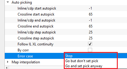
Stop - it stops the horizon auto picking without proceeding further.
Go but don't set pick - it will continue working, however it won't pick the horizon
Go and set pick anyway - it will move forward and continue picking the horizon of the remaining inline/cdp and/or crossline.
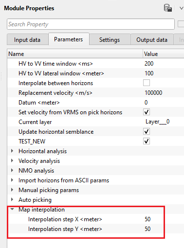
Map interpolation - it performs the interpolation of the picked horizons and creates a map.
Interpolation step X - specify the interpolation step size in X - direction. By default, 50
Interpolation step Y - specify the interpolation step size in Y - direction. By default, 50
![]()
![]()
SegyCacheParams
SegyReadParams - parameters for setting advanced parameters of reading seismic traces from disk
Thread count (for SSD) - amount of treads for reading seismic traces from disk.
Bulk size (traces) - size of a chunk (data portion) for reading seismic traces from disk.
Number of threads - One less than total no of nodes/threads to execute a job in multi-thread mode. Limit number of threads on main machine.
Skip - By default, FALSE(Unchecked). This option helps to bypass the module from the workflow.
![]()
![]()
Output horizons - generates output horizons as an vista item.
Reference stack inline - generates vista item for inline stack as reference
Reference stack crossline - generates vista item for cross stack as reference
Horizontal VRMS inline - generates vista item for Horizontal Inline VRMS
Horizontal VRMS xline - generates vista item for Horizontal Crossline VRMS
Stack inline - generates inline stack as a vista item
Stack crossline - generates crossline stack as a vista item
Selected seismogram - generates selected seismogram as vista item
Selected seismogram NMO - generates selected NMO seismogram as vista item
Horizontal velocity semblance inline - generates inline horizontal velocity semblance
Horizontal velocity semblance xline - generates crossline horizontal velocity semblance
There is no information available for this module so the user can ignore it.
![]()
![]()
In this example workflow, we are working on a 3D dataset (Tea pot dome 3D). For a 3D dataset, we need to have full 3D stack & velocity volumes as Input(s) besides the prestack data as Input data.
After making necessary connections/references, launch the vista items. It will have many vista items, out of those, location map, reference inline and reference crossline are important at the beginning.
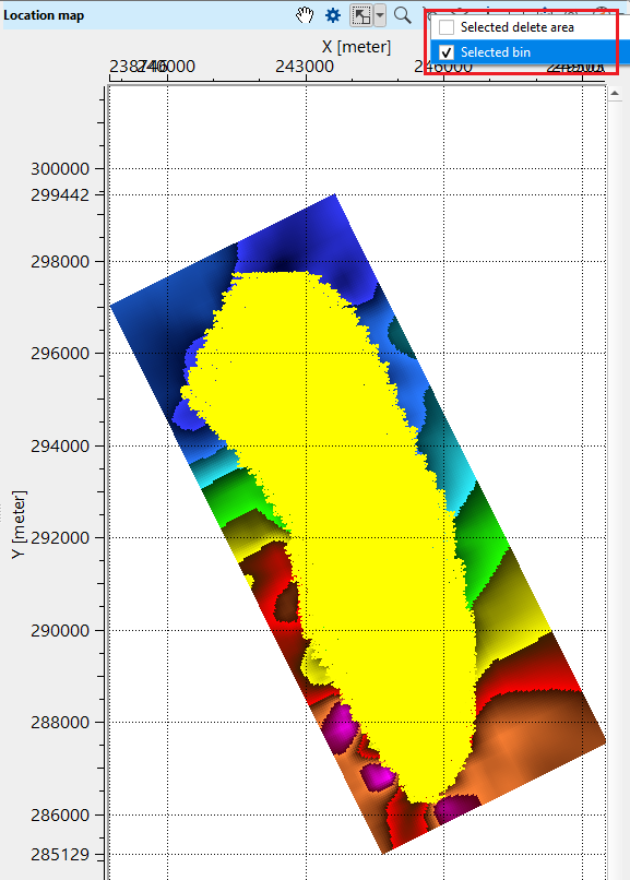
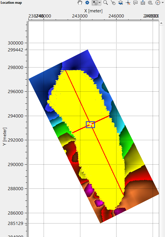
•Go to location map and click "Select bin" from the control item icon ![]() . Click anywhere randomly on the location map (within the survey area). It will mark inline and cross lines. Inside the BLUE polygon, it is our selected bin.
. Click anywhere randomly on the location map (within the survey area). It will mark inline and cross lines. Inside the BLUE polygon, it is our selected bin.
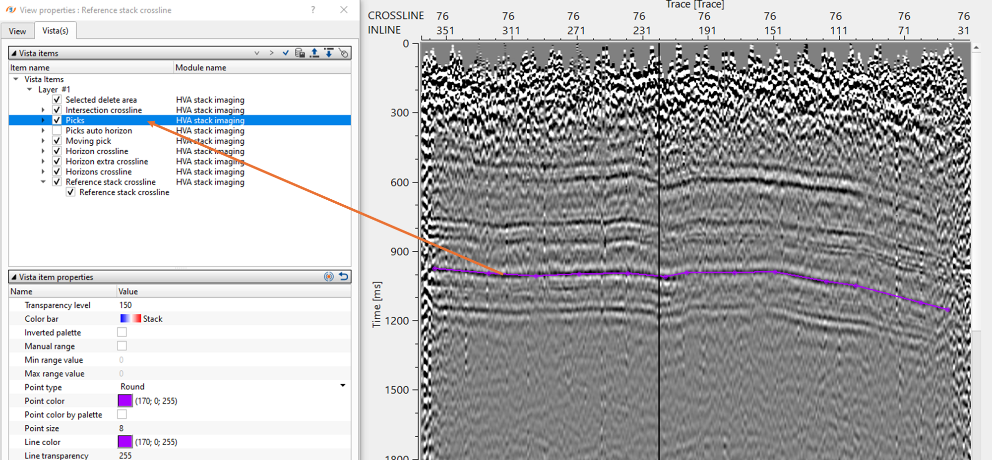
•Go to Reference inline/crossline and click "Picks" from the control item ![]() icon.
icon.
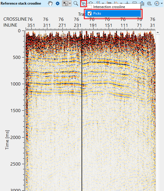
•Now on the Reference inline/crossline, start picking the horizon. It should be done by, holding MB1 or LMB1 and start picking. There will be two types of points appear on the reference inline/crossline. One is purple (horizon picks) & other one is green (horizon auto picks).
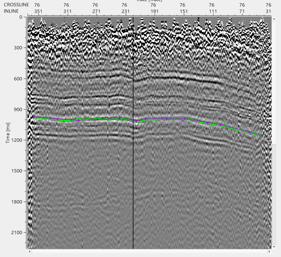
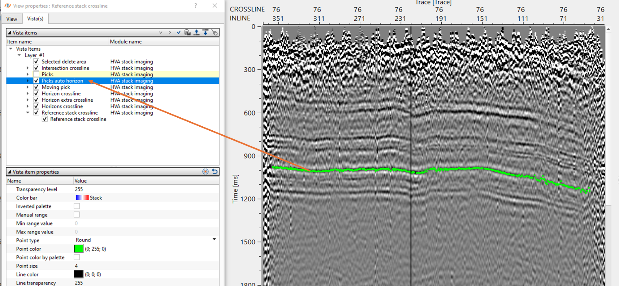
•Adjust the automatic picks within the parameters. To remove any bad picks, hold RMB1 or MB3 and draw any polygon within the bad picks area. Any picks falling inside this polygon will be removed.
•To make these picks as horizon, hold ALT+MB3 or RMB
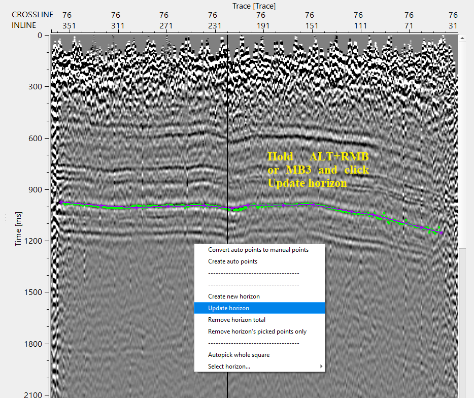
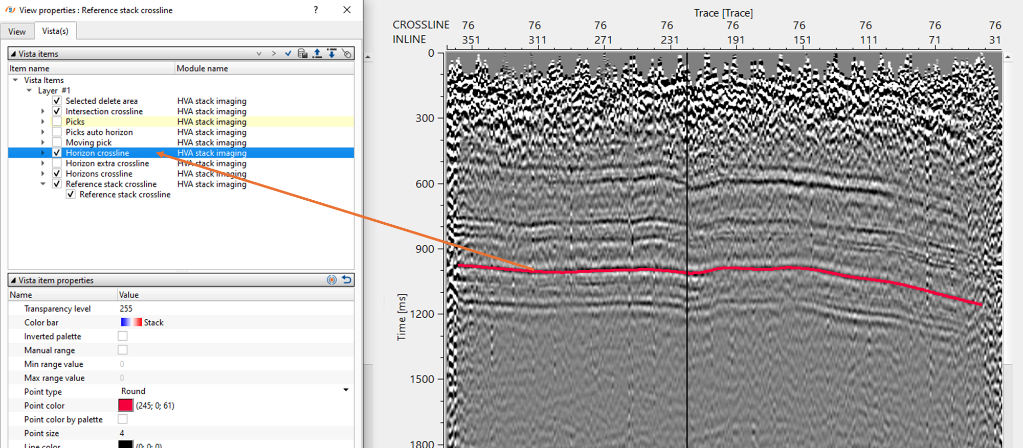
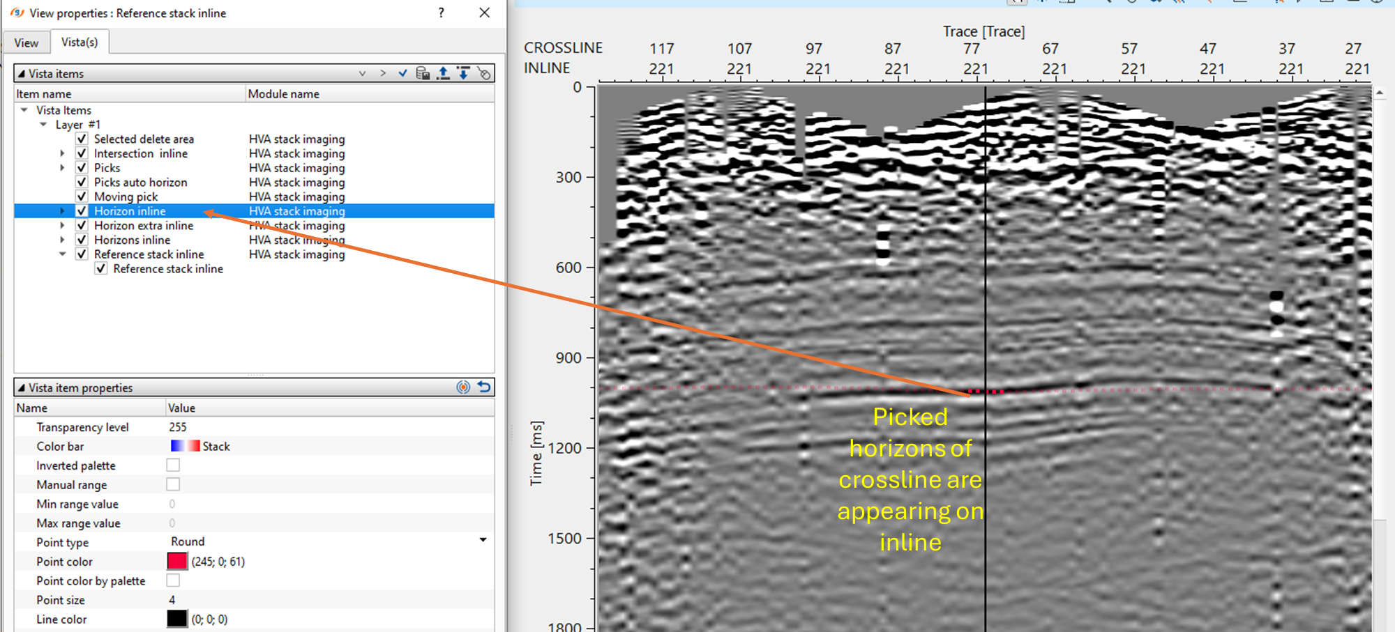
After updating the horizon, there are few QC items available for visual inspection. The user should pick the horizons for any inline and/or crossline and update the horizon. This will update the location map with interpolated horizon map(s).
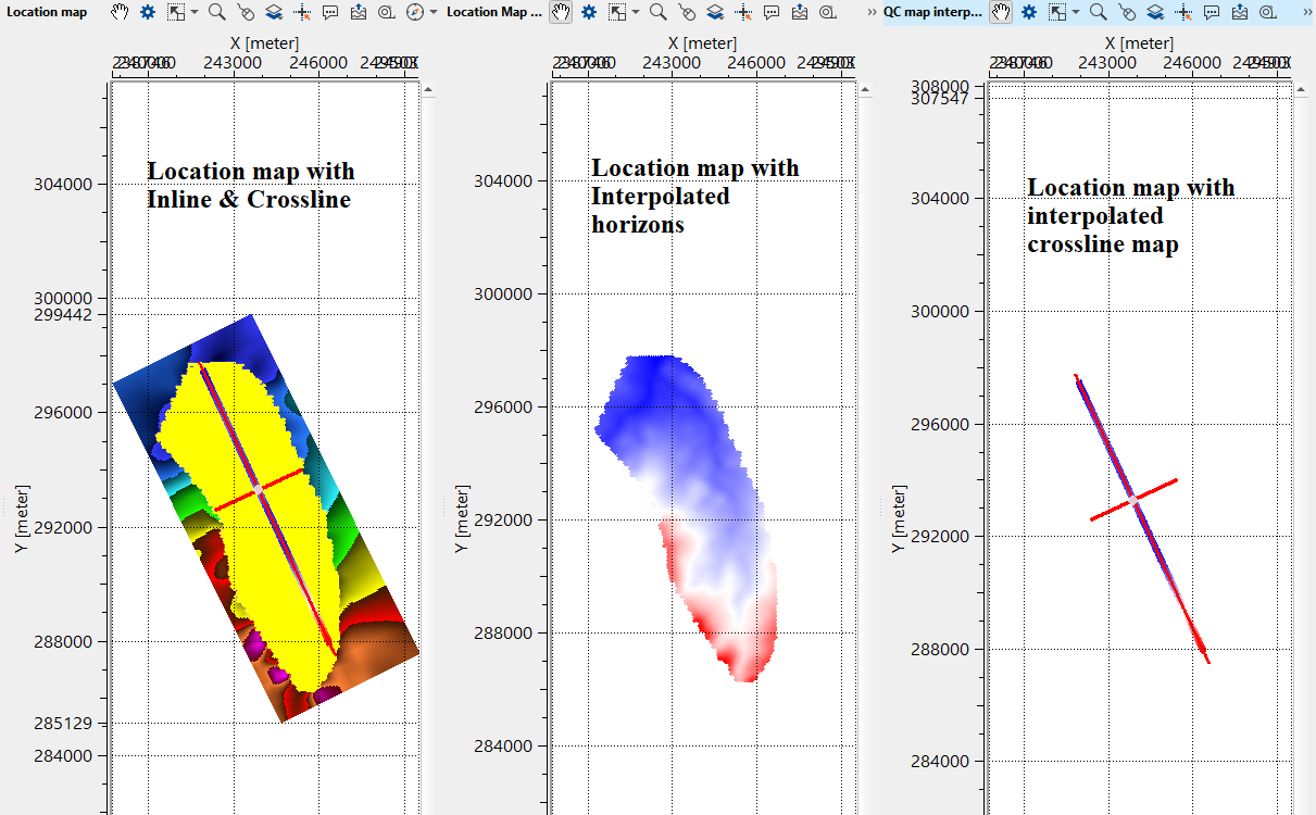
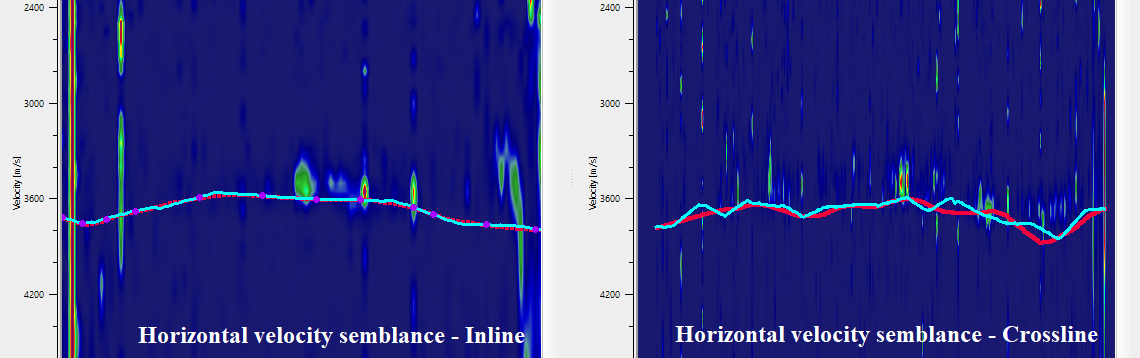
There are horizontal semblance displays for both inline and crossline. The picked horizons appear on these semblance display. The user can also adjust the horizon picks on the horizontal semblance based on the semblance response.
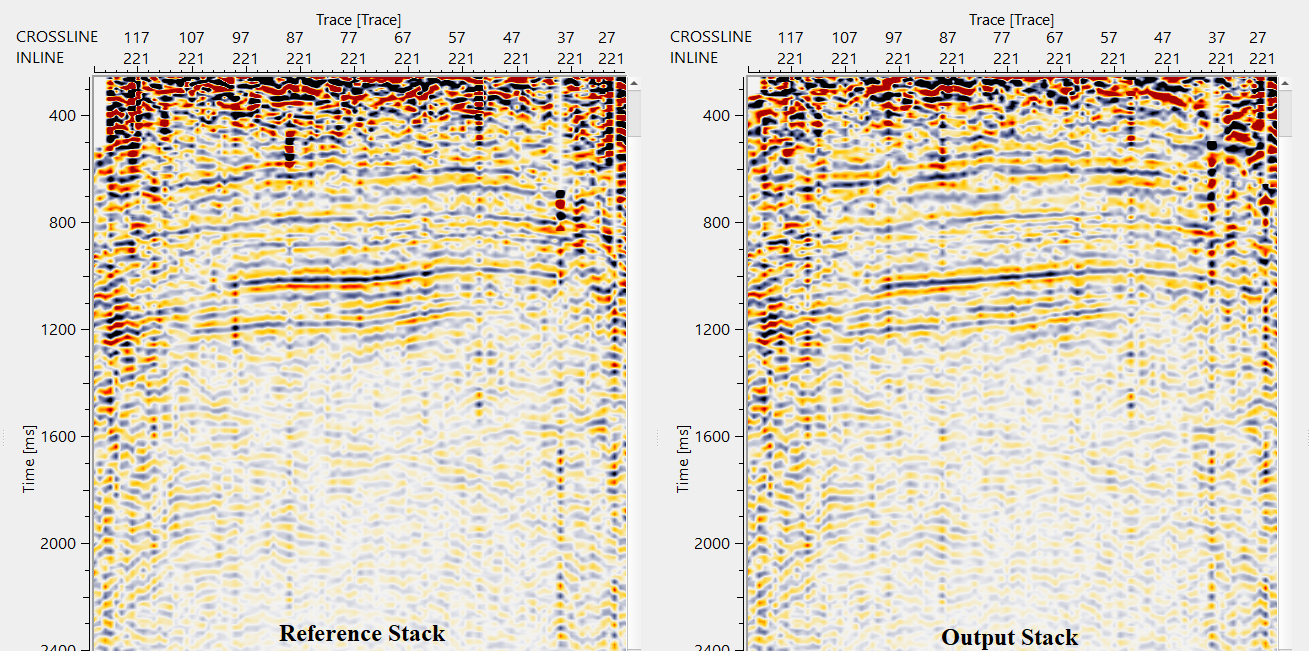
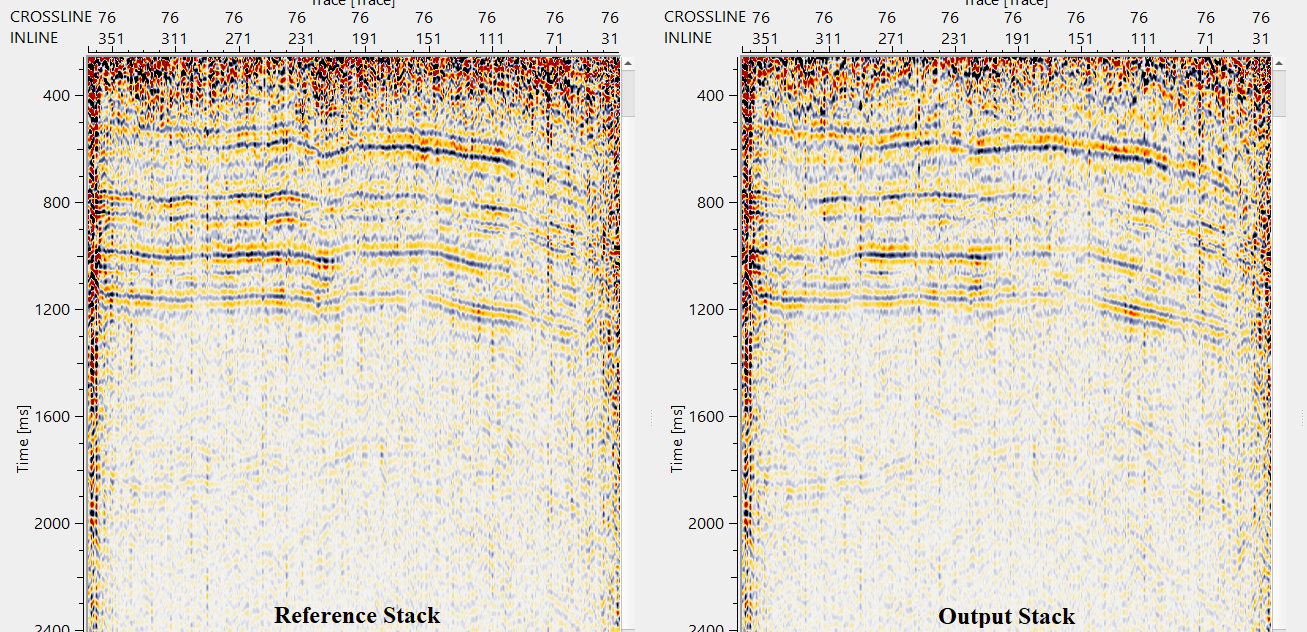
Likewise, the user can pick the horizons for the entire volume. Adjust the parameters for interpolation, semblance, HV to VV time window etc and execute the module. It will give updated inline and crossline stack sections as output inline/crossline stack. Compare them against the reference inline/crossline stack and see if there is any improvement in the stack response.
![]()
![]()
Import horizon ASCII - with this option, it allows the user to import the horizons in ASCII (text) format.
Export horizons ASCII - export the picked horizons in ASCII (text) format.
-------------------
Save horizons binary - save the picked horizons in binary format.
Load horizons binary - load the picked horizons/previously saved horizons in binary format.
-------------------
Fill auto pick points crosslines by manual points (only btw manual points) - fills horizon auto picking points in crossline direction by manual points.
Fill auto pick points inlines by manual points (only btw manual points) - fills horizon auto picking points in inline direction by manual points.
Fill auto pick points crosslines by map - fills horizon auto picking in crossline direction by map.
Fill auto pick points inlines by map - fills horizon auto picking in inline direction by map.
Fill auto pick points crosslines by manual points (tracking) - by tracking method, fills horizon auto picking points in crossline direction by manual points.
Fill auto pick points inlines by manual points (tracking) - by tracking method, fills horizon auto picking points in crossline direction by manual points.
-------------------
Remove all horizons - by clicking this option, removes all the picked horizons.
![]()
![]()
YouTube video lesson, click here to open [VIDEO IN PROCESS...]
![]()
![]()
Yilmaz. O., 1987, Seismic data processing: Society of Exploration Geophysicist
 * * * If you have any questions, please send an e-mail to: support@geomage.com * * *