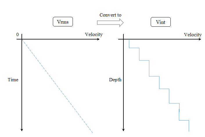
3D RMS velocity [time domain] conversion into Interval velocity [depth domain] (PSDM stage)
![]()
![]()
Velocity conversion from the time domain to the depth domain is a crucial step in seismic data processing, enabling accurate subsurface imaging. In the time domain, seismic velocities are typically represented as root-mean-square (RMS) velocities, which describe the average velocity of seismic waves as they travel through multiple layers of the Earth's subsurface. However, for depth imaging and structural interpretation, interval velocities - representing the velocity within individual geological layers - are required. The conversion from time to depth is achieved using the Dix formula, which extracts interval velocities from RMS velocities by considering the changes in travel time and velocity at different depths. In the module there are two types of calculation: conventional Dix and Dix inversion. The first method is called Dix in the module's parameters:
The Dix formula is given by:
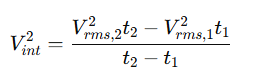
where Vint is the interval velocity between two depth levels, Vrms1, and Vrms2 are the RMS velocities at two-way travel times t1 and t2, respectively. This equation allows for the estimation of interval velocities by analyzing the changes in RMS velocities with respect to time. Since RMS velocities are derived from seismic stacking processes, the Dix formula enables geophysicists to transform these velocities into a depth-consistent representation, which is essential for constructing accurate geological models.
Applying the Dix formula is particularly important in complex geological settings where velocity variations significantly impact seismic wave propagation. Proper velocity conversion helps in depth migration, well-tie calibration, and hydrocarbon reservoir characterization. However, errors in RMS velocity picking or assumptions about layer homogeneity can introduce inaccuracies in interval velocities. To improve precision, additional techniques such as tomographic inversion and well-log calibration are often employed.
The second method is called Inversion in the module parameters. Dix inversion is more complex and may be effective in case of of we have very accurate RMS velocity. Dix inversion performs equations via Dix formula and executes inversion solver iteratively. Usually, we recommend use Dix option (no inversion) for velocity conversion.
This module performs seismic velocity inversion by transforming root-mean-square (RMS) velocities (Vrms) into interval velocities (Vint) using the Dix formula. Unlike a direct one-pass Dix inversion, this module implements iterative optimization techniques, performing multiple global and local iterations to refine the interval velocity model by minimizing errors or misfits. This iterative approach enhances accuracy and robustness, especially in complex geological settings where simple Dix inversion may lead to unrealistic velocity variations.
By systematically adjusting interval velocities and assessing misfits between observed and calculated velocity models, the module improves depth consistency and geological reliability. The optimization process ensures that the resulting interval velocities are not just mathematically computed but also geophysically meaningful.
Methodology
The module follows an iterative approach to velocity inversion:
1.Input Data: The module requires RMS velocities (Vrms) and corresponding two-way travel times (t), which are typically derived from seismic processing (e.g., stacking velocity analysis).
2.Initial Dix Inversion: A first-pass estimation of interval velocities is computed using the classic Dix formula: 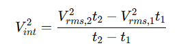
3.Global and Local Iterations: The module refines the initial interval velocity model using iterative optimization. This includes:
oGlobal Search: Broad adjustments across the entire velocity model to find an optimal solution that reduces overall misfit.
oLocal Refinements: Fine-tuning of interval velocities within specific depth intervals to minimize localized errors.
4.Misfit Minimization: At each iteration, the module evaluates the misfit (error between observed and modeled velocities) and updates the interval velocity values accordingly. The process continues until the misfit reaches a predefined minimum threshold or convergence criteria.
5.Output Generation: The final optimized interval velocity model is produced, providing a geologically consistent velocity profile suitable for depth imaging, migration, and reservoir characterization.
![]()
![]()
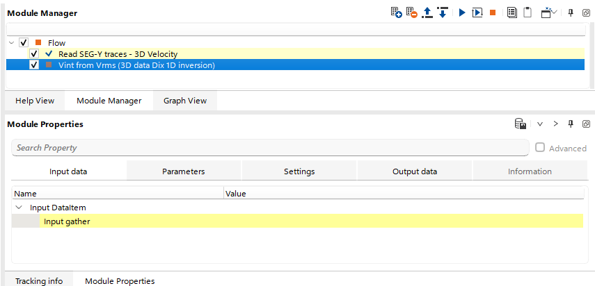
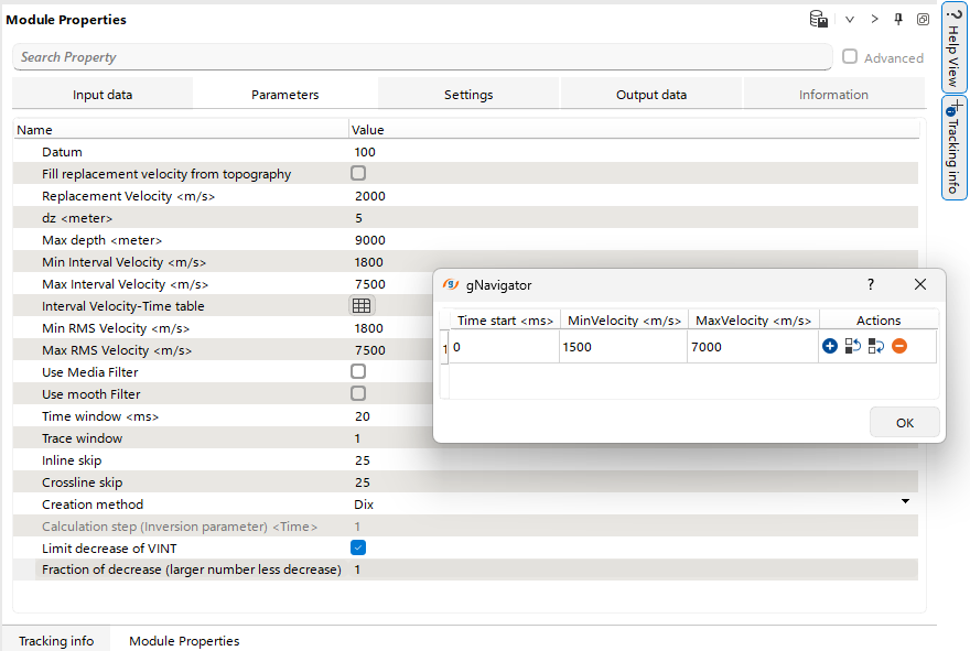
Input DataItem
Input gather - Input RMS velocity gather (uploaded into RAM).
![]()
![]()
Datum - constant datum plane (in meters) for the output interval velocity.
Replacement Velocity - replacement velocity (m/s) for datum plane.
dz - vertical resolution / depth step / sample interval.
Max depth - maximum depth for output velocity model.
Min Intervalt Velocity - limit minimum interval velocity.
Max Intervalt Velocity - limit maximum interval velocity.
Interval Velocity-Time table - limitation travel time table: time -min velocity - max velocity.
Min RMS Velocity - limit minimum RMS velocity.
Max RMS Velocity - limit minimum RMS velocity.
Use Media Filter - apply median filter for RMS velocity before conversion.
Use mooth Filter - apply smooth filter for RMS velocity before conversion.
Time window - time (vertical) sliding window for filters.
Trace window - trace (horizontal) sliding window for filters.
Inline skip - net of inlines selection, with increment (skip), which is extracted from the input Vrms.
Crossline skip - net of xlines selection, with increment (skip), which is extracted from the input Vrms.
Creation method: select an algorithm for conversion
Dix - conventional Dix conversion, see explanation in the theory part of this documentation (recommendation: use it).
Inversion - complex Dix inversion, see explanation in the theory part of this documentation.
Calculation step (Inversion parameter) - travel time calculation step for inversion parameter
Limit decrease of VINT - enable Fraction of decrease parameter:
Fraction of decrease (larger number less decrease) - in accordance with this factor an output velocity may be decreased with respect to the previous depth sample.
Solver parameters - for inversion method only!!! (not for Dix option).
Interval velocity X-step - output velocity resolution in meters along X direction.
Interval velocity Y-step - output velocity resolution in meters along Y direction.
Interval velocity Z-step - output velocity vertical resolution in meters.
Equation step by X - Dix equations cell-resolution in meters along X direction. Should be less than interval velocity parameter. For example: Interval velocity X-step = 1200, Equation step by X = 600.
Equation step by Y - Dix equations cell-resolution in meters along Y direction. Should be less than interval velocity parameter.
Equation step by Z - Dix equations vertical resolution in meters. Should be less than interval velocity parameter.
Number of global iterations - number of inversion iterations for solver.
Tolerance - parameter stops solver when the solver should stop based on the reduction of misfit between observed and calculated velocities.
Max iterations - number of local iterations inside each global iteration.
Regularization by X weight - smoothness coefficient for solution stabilization, i.e. more smooth - less velocity anomalies.
Regularization by Y weight - smoothness coefficient for solution stabilization, i.e. more smooth - less velocity anomalies.
Regularization by Z weight - smoothness coefficient for solution stabilization, i.e. more smooth - less velocity anomalies.
Remove inversions - remove all inversions on the output velocity.
![]()
![]()
Auto-connection - module is connected with previous (and next) modules in the workflow by default.
There are 3 options for corrupted (NaN) samples in trace:
Fix - fix corrupted samples.
Notify - notify and stop calculations.
Continue - continue calculations without fixing.
Skip - switch-off this module (do not use in the workflow).
![]()
![]()
Output DataItem
Output gather - resulting interval velocity model.
Interval depth velocity - resulting interval velocity model.

There is no information.
![]()
![]()
There is no actions.
![]()
![]()
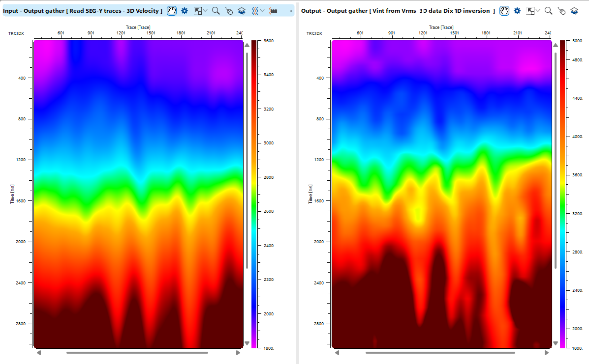
There in an example for conversion Vrms into Vint via Dix (3D) module:
On he left there is an Input RMS velocity and on the right it is output interval velocities:
![]()
![]()
 If you have any questions, please send an e-mail to: support@geomage.com