3D regularization using Offset Vector Tiles method (mid point consistent)
![]()
![]()
Regularization in 3D seismic processing reorganizes irregularly sampled field data into a uniformly spaced 3D grid (inline, crossline, and time/depth). This ensures data compatibility with processing algorithms (e.g., migration, inversion) that assume regular sampling. Midpoint consistency ensures that traces sharing the same midpoint (midway between source and receiver) are grouped and interpolated spatially and azimuthally without bias.
Offset Vector Tile (OVT) is a modern regularization framework that preserves offset (distance between source and receiver) and azimuth (direction of the source-receiver pair) information. It partitions data into "tiles" based on offset vectors, enabling high-fidelity imaging and amplitude analysis.
OVT is nothing but a subdivision of CMP bin into smaller offset sectors. For each CMP bin, Offset range is divided into offset bins like 0–500 m, 500–1000 m, etc.
How does regularization process works in OVT?
•Define a target bin grid with regularized offset.
•For Each CMP bin, traces are allocated to corresponding OVT
•Trace selection is done by selecting traces within the user defined offset with a certain aperture in inline/crossline direction.
•Final output is a regularized CMP bins with uniform offset tiles.
![]()
![]()
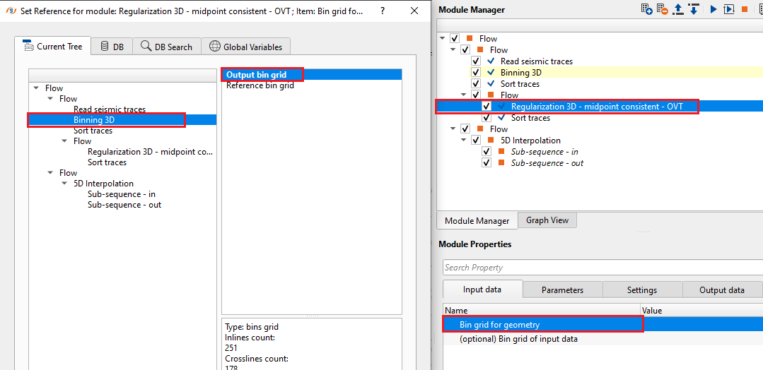
Bin grid for geometry - connect/reference to target bin grid for geometry. This is target/expected bin grid information.
(optional) Bin grid of input data - this is optional parameter however if the user requires, connect/reference to the input data bin grid.
![]()
![]()
Create geometry using fold - by default, TRUE (Checked). It creates the geometry based on the fold. If there are zero fold traces then it won't create the geometry for that region.
Max distance to valid bin - specify the maximum distance from the selected/valid bin.
Elevation type { Smoothed, Precise, Bin elev } - select the type of elevation to be considered from the drop down menu. By default, Smoothed which is stored in the trace headers (Binning 3D smooths the elevations which acts as floating datum).
smoothed - smoothed version of elevations
Precise - original topography elevations.
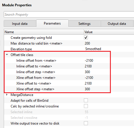
Offset tile class - in OVT, offsets are divided into offset bins/tiles.
Inline offset from - specify the starting offset of inline
Inline offset to - specify the last/ending offset of inline
Inline offset step - specify the offset step size in inline direction
Xline offset from - specify the starting offset of crossline
Xline offset to - specify the last/ending offset of crossline
Xline offset step - specify the offset step size in crossline direction
![]()
![]()
Number of threads - One less than total no of nodes/threads to execute a job in multi-thread mode. Limit number of threads on main machine.
Skip - By default, FALSE(Unchecked). This option helps to bypass the module from the workflow.
![]()
![]()
Trace headers geometry - generates the regularized output trace headers geometry for further use.
![]()
![]()
Nominal traces count - total number of nominal traces. Based on the user provided inline, crossline offsets and offset step size, it generates the nominal trace count. For example, inline offsets are defined as (-2100, 2100 with a offset step size of 300m) & Crossline offset as (-2100, 2100 with a offset step size of 300 m ), each creates 14 tiles. so 14x14 = 196 nominal traces will be created.
![]()
![]()
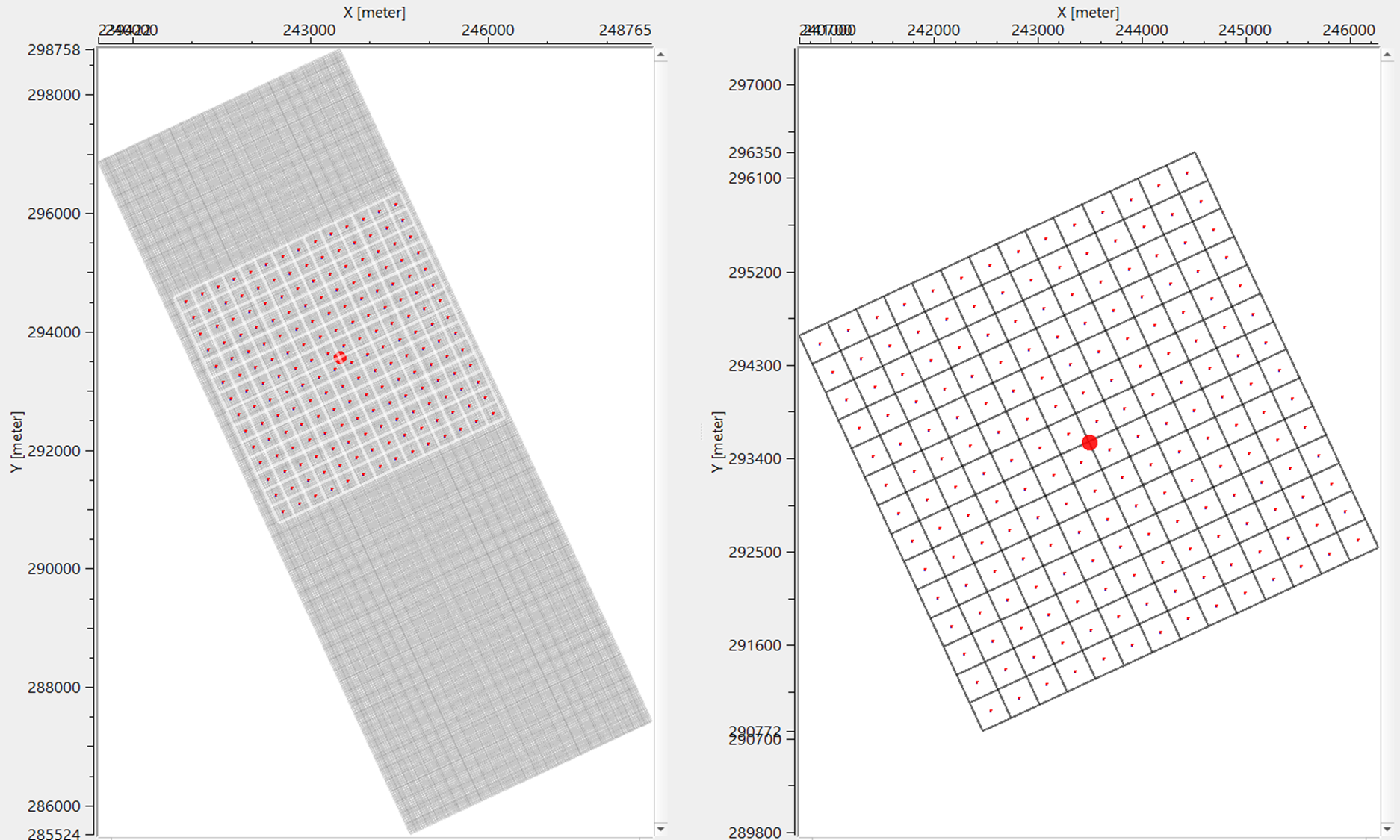
In this example workflow, we create regularization using OVT. Bin Grid geometry can be anything (target/input). Optionally, if the user wants to use a different bin grid then provide the optional bin grid of the input data.
In the parameters, we are regularizing the data with the following parameters
If we look at the offset tile class, with the above parameters we create 196 (14x14) tiles. We consider Inline offset ranges from -2100 to 2100 with a set size of 300 which creates 14 tiles in inline direction. Similarly, for crossline direction there will be 14 tiles. So in total, it will be 196. Assign the appropriate parameters as per the input data requirements and execute the module. It generates Location map as a vista item.
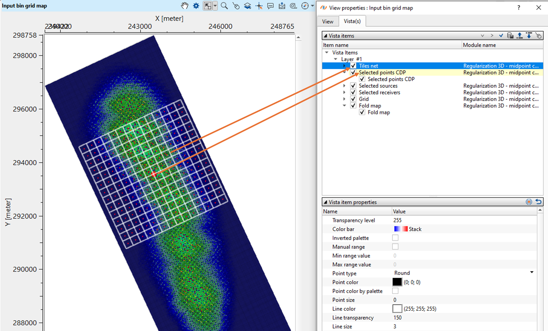
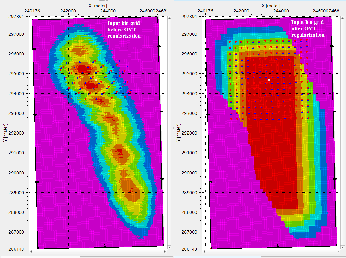
After the regularization, check the location map of before and after OVT regularization by binning the Output trace headers of Regularization 3D - mid point consistent - OVT module.
![]()
![]()
There are no action items available for this module so the user can ignore it.
![]()
![]()
YouTube video lesson, click here to open [VIDEO IN PROCESS...]
![]()
![]()
Yilmaz. O., 1987, Seismic data processing: Society of Exploration Geophysicist
 * * * If you have any questions, please send an e-mail to: support@geomage.com * * *