Surface Consistent Virtual 2D geometry
![]()
![]()
In seismic data processing, regularization refers to reorganizing irregularly sampled field data into a uniformly spaced grid to meet the requirements of imaging algorithms (e.g., migration, inversion). Virtual Surface Consistent Regularization extends this concept by ensuring that data is regularized with respect to a virtual surface—a hypothetical or constructed 2D grid that represents an idealized acquisition geometry. This method enforces consistency across the virtual surface, addressing spatial and amplitude irregularities while preserving subsurface geological features.
A virtual surface is a predefined 2D grid (e.g., a regular x-y plane or a curved surface) onto which seismic traces are interpolated or mapped.
Unlike midpoint-based regularization (which focuses on source-receiver midpoints), the virtual surface is designed to optimize data alignment for specific processing goals, such as amplitude preservation or noise suppression.
Surface-consistent methods assume that variations in seismic data (for example, amplitudes, travel times) are systematic and tied to source/receiver locations or the acquisition surface.
For example, Surface-consistent amplitude corrections adjust for source/receiver coupling variations. Surface-consistent deconvolution removes source/receiver-dependent wavelets. In regularization, "surface consistency" ensures that interpolated or extrapolated data adheres to the geometric and physical properties of the virtual surface.
Real-world seismic surveys often have gaps, fold variations, or irregular source/receiver spacing due to obstacles or logistical constraints. Surface-consistent regularization minimizes artifacts that distort amplitude-vs-offset (AVO) or amplitude-vs-azimuth (AVAz) signals. Algorithms like reverse-time migration (RTM) or full-waveform inversion (FWI) require regular input grids to avoid numerical instability or misinterpretation.
![]()
![]()
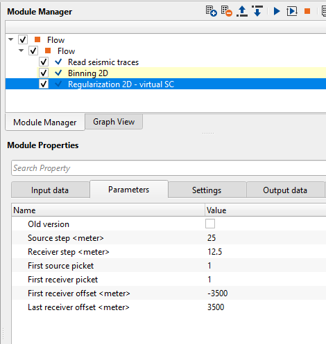
Crooked Line - Link to median CMP line consist of coordinates X, Y (output data from “Binning2D”).
![]()
![]()
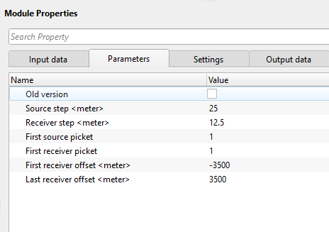
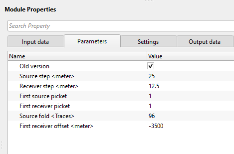
Old version - By default, FALSE (Unchecked). This option has additional parameter like Source fold.
Source fold - number of receivers in one source.
First receiver offset - specify the near offset or the first receiver maximum offset information
Source step - source interval or distance between two adjacent sources. Specify the source step size.
Receiver step - receiver interval or distance between two adjacent receivers. Specify the receiver step size for virtual geometry creation.
First source picket - any sources below this specified number will not be considered. Specify the first source picket number. By default, 0.
First receiver picket - any receivers below the user specified number will not be considered. Specify the first receiver picket number. By default, 0.
First receiver offset - specify the near offset or the first receiver maximum offset information.
Last receiver offset - specify the far offset or the last receiver maximum offset information.
![]()
![]()
Skip - By default, FALSE(Unchecked). This option helps to bypass the module from the workflow.
![]()
![]()
Trace headers - generates updated output trace headers after regularization.
There is no information available for this module so the user can ignore it.
![]()
![]()
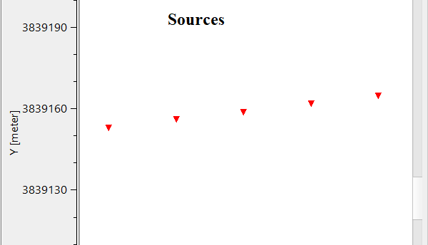
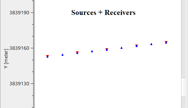
In this example workflow, we create a surface consistent virtual geometry for a crooked 2D line.
![]()
![]()
There are no action items available for this module so the user can ignore it.
![]()
![]()
YouTube video lesson, click here to open [VIDEO IN PROCESS...]
![]()
![]()
Yilmaz. O., 1987, Seismic data processing: Society of Exploration Geophysicist
 * * * If you have any questions, please send an e-mail to: support@geomage.com * * *