Normalization of the seismic signal amplitudes
![]()
![]()
The Balance module applies a time-varying amplitude scaling to each seismic trace, normalizing the overall signal level toward a user-defined target amplitude. It is commonly used to equalize amplitude variations across a gather or section caused by geometric spreading, near-surface effects, or acquisition differences — making it easier to interpret reflection character and continuity.
For each trace, the module measures the average absolute amplitude in a series of overlapping sub-windows spanning the specified analysis time gate (Start window to End window). It then computes a smoothly interpolated scaling function along the trace, where the scalar at any point equals the target Level value divided by the local average amplitude. This scalar is applied sample-by-sample, bringing quiet intervals up and loud intervals down toward the same target level. The result preserves relative amplitude character within each local window while balancing the overall trace envelope.
Balance can be applied to both pre-stack data (shot, receiver, or CMP gathers) and post-stack data (stacked sections). It is particularly useful as a display conditioning step or as a pre-processing step before attribute extraction, when consistent amplitude levels across the dataset are required.
![]()
![]()
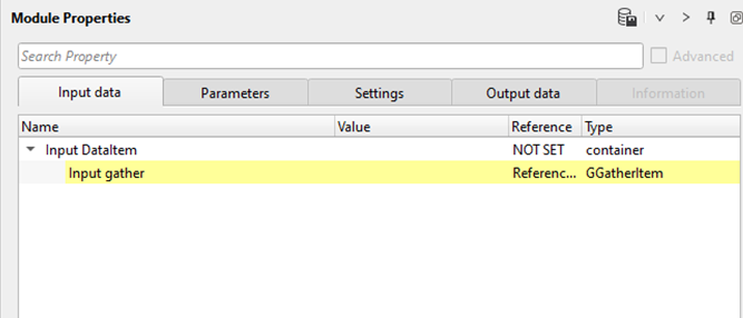
Input DataItem -
The Input DataItem container holds the connections that supply seismic data to the Balance module.
Input gather - connect/reference to the input gather. Balance can be applied to pre-stack data like shot/receiver/cmp gather as well as post stack data like stack sections.
Connect this item to the output gather of the preceding module in the workflow — for example, the output of a Read Seismic Traces or a previous processing module. The module processes each gather or section independently, trace by trace.
![]()
![]()
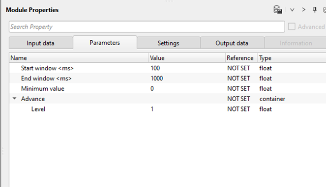
Start window - Start time gate for amplitude scalar calculation.
Sets the beginning of the time gate (in seconds) over which the amplitude analysis is performed. The module will measure average amplitudes and compute balancing scalars starting from this time. The default value is 0.1 s. Set this to the top of the zone of interest, typically just below the water bottom or first-break mute level. This value must be smaller than the End window value.
End window - End time gate for amplitude scalar calculation.
Sets the end of the time gate (in seconds) over which amplitude analysis is performed. The default value is 1.0 s. Set this to the bottom of the zone of interest. The window between Start window and End window should span the primary reflection interval you wish to balance. A wider window produces a smoother, more gradually varying scalar function along each trace.
Minimum value - By default, 0. This is the minimum maximum normalization method. So the value can be from 0 to 1. Anything above these values creates spikes or spurious amplitudes.
Sets the minimum amplitude threshold used to identify live signal on a trace. Any sample whose absolute value falls below this threshold at the beginning or end of the trace is treated as a dead (zero) sample and excluded from the amplitude analysis. This protects against dividing by near-zero values on dead or very low-energy traces, which would otherwise produce enormous, spurious scalars. The default value is 0 (dimensionless amplitude units). If your data contains noisy dead traces or header-padded zeroed samples, increase this value slightly to avoid boosting noise in silent trace segments. If the average amplitude in a sub-window falls below this threshold, the module substitutes the target Level value to prevent unstable scaling.
Advance
The Advance group contains the target amplitude level parameter for the balancing operation.
Level - Desired amplitude value. By default, 1
Sets the target amplitude value (in native data units) that the balancing operation aims to achieve. The scaling scalar applied to each trace segment is computed as this Level value divided by the local average absolute amplitude of that segment. The default value is 1. At the default setting, all traces are scaled so that their average absolute amplitude across each local sub-window approaches 1. You may change this value to match the desired amplitude range of your data — for example, set it to 10,000 to target a mean absolute amplitude of 10,000 counts. Setting Level to a negative value is equivalent to using the default of 1.
![]()
![]()
Auto-connection - By default Yes (Checked)
When enabled (default), g-Platform automatically connects this module to compatible upstream and downstream modules in the workflow. Disable this option only if you need to manually control data routing between modules.
Bad data values option { Fix, Notify, Continue } - This is applicable whenever there is a bad value or NaN (Not a Number) in the data. By default Notify. While testing, it is good to opt as Notify option. Once we understand the root cause of it, the user can either choose the option Fix or Continue. In this way, the job won't stop/fail during the production
Controls how the module responds when it encounters invalid amplitude values (NaN or infinity) in the input data. Notify (default) logs a warning message and stops the job so you can investigate the cause. Fix automatically replaces bad values with zero and continues processing — use this in production once you have confirmed the bad values are an expected artifact. Continue passes the bad values through unchanged — use only if downstream modules are designed to handle them.
Calculate relation - It calculates the amplitude relation and gives as an output.
When enabled, the module computes and outputs the amplitude relation data — the ratio of the original to the balanced amplitudes — in addition to the balanced gather. This output can be connected to a downstream module for QC analysis or for saving the scalar field. Enable this option when you need to inspect or archive the applied gain function.
Number of threads - One less than total no of nodes/threads to execute a job in multi-thread mode.
Controls the number of CPU threads used for parallel processing. Balance processes traces in parallel, so increasing this value speeds up execution on multi-core systems. Set this to the number of available CPU cores minus one (to leave one core free for system tasks). For example, on an 8-core machine, a value of 7 is recommended. The default is determined by the system configuration.
Skip - By default, No (Unchecked). This option helps to bypass the module from the workflow.
When set to Yes, the Balance module is bypassed and data passes through unchanged. Use this to temporarily disable balancing during workflow testing without removing the module from the processing sequence.
![]()
![]()
Output DataItem
The Output DataItem container holds the connections that carry processed results out of the Balance module to downstream modules.
Output gather - Outputs the Balance applied gather (shot/receiver/cmp) or stack section.
Contains the amplitude-balanced seismic data. Each trace has been scaled by the time-varying scalar computed from the analysis window, with amplitudes normalized toward the target Level. Connect this output to the Input gather of the next module in your workflow — for example, a Write Seismic Traces module, a display module, or a further processing step.
Amplitude relation - Outputs the amplitude relation.
When the Calculate relation option is enabled, this output carries the amplitude scalar field computed by the module — that is, the ratio of the target Level to the measured local amplitude for each trace. This data can be connected to a downstream module for QC inspection or archiving of the applied gain function.
![]()
![]()
In this below example, we are reading a stack section using "Read seismic traces" and load data to RAM as Yes option. Now, we add Balance and reference/connect the Output gather from the "Read seismic traces" module to Balance module.
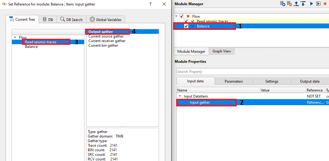
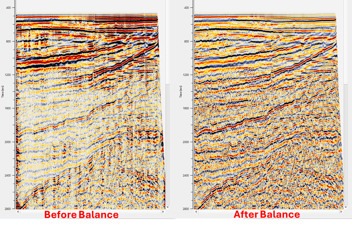
We apply default parameters to the stack section and we'll get stack before and after Balance application.
![]()
![]()
There are no action items are existing for this module so the user can ignore it.
![]()
![]()
YouTube video lesson, click here to open [VIDEO IN PROCESS...]
![]()
![]()
Yilmaz. O., 1987, Seismic data processing: Society of Exploration Geophysicist
 * * * If you have any questions, please send an e-mail to: support@geomage.com * * *