Slopes picking on a stack section for tomography (PSDM stage)
![]()
![]()
A Create tomo slopes module is a key component in the tomography update process during the Pre-Stack Depth Migration (PSDM) workflow. This module is used to extract the slopes (or dip angles) of reflection events from a stacked seismic section, where offsets have been collapsed into a single zero-offset representation. The extracted slopes correspond to the local inclination of reflectors in the time domain and are crucial for refining the velocity model in tomographic inversion processes.
In this context, the slope p is determined as the spatial derivative of travel time along the stacked section:
where t represents the travel time of a reflection event, and x is the horizontal spatial coordinate. These slopes provide information about the geometric characteristics of reflectors, which is used in tomographic updates to improve the subsurface velocity model. By incorporating this slope data, tomography can better constrain the adjustments to the velocity model, geological horizons and improve the accuracy of ray path calculations.
The create tomo slopes module is particularly important for imaging in areas with complex geological features, such as dipping layers or faults. The precise picking of slopes from the stack section ensures accurate input for tomographic inversion, which iteratively updates the velocity model. This leads to a more accurate representation of subsurface structures and improves the fidelity of the final seismic image for exploration and reservoir characterization workflows.
![]() The module requires stack in time domain, therefore we need to convert depth stack section from depth domain to time.
The module requires stack in time domain, therefore we need to convert depth stack section from depth domain to time.
Also pay attention to Visualization slope picking: if may take time for rendering and it consumes computer's resources.
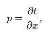
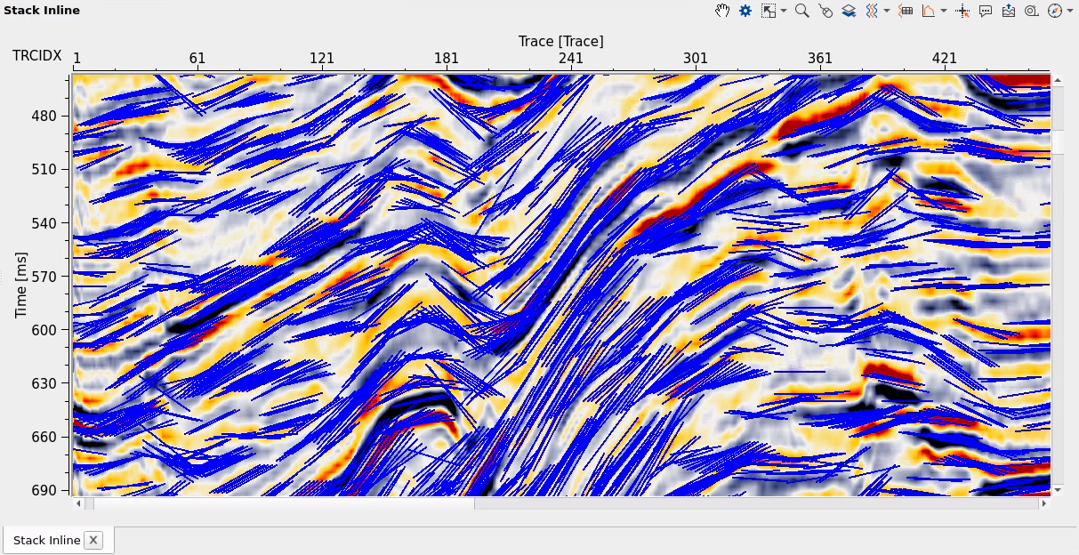
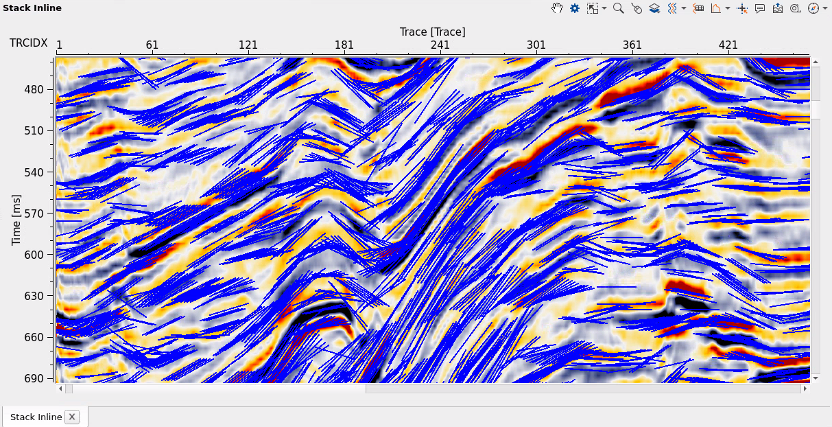
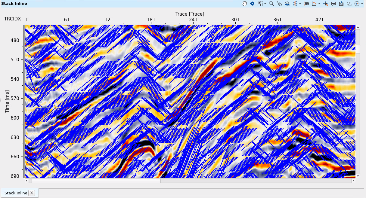
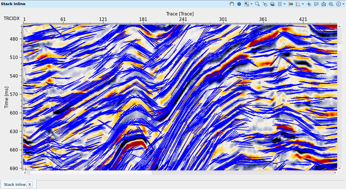
Pic. 1 Slope picks (blue) and PSDM stack section in time domain ("tiger" palette).
![]()
![]()
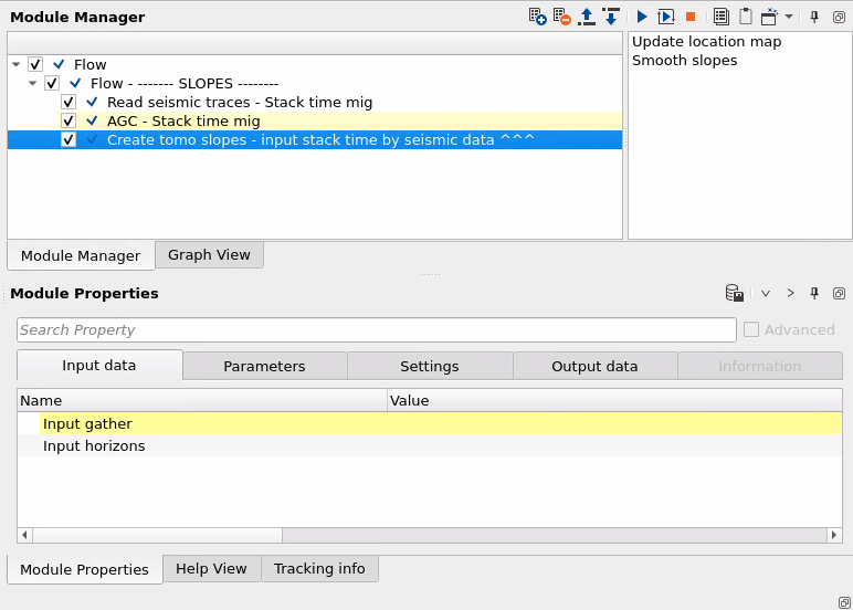
Input gather - connect the seismic stack gather here. The data must be in the time domain and loaded into RAM. This is typically a PSDM stack section that has been converted from depth to time. If the stack is already referenced to a constant datum, leave the Shift to datum parameter disabled.
Input horizons - (optional) connect previously picked horizon items here. When connected and the Slope input parameter is set to Horizons, the module computes slopes directly from the geometry of these horizon picks rather than from the seismic amplitude data. This path is faster and deterministic, and is preferred when reliable horizons are already available.
![]()
![]()
Slope input - select which data will be used for slope picking:
Horizons - if we have horizons item on the input, so this option performs slope picking only on these piked horizons (without using seismic data).
Seismic data - select this option in case of input data is seismic stack, so slope picking will be performed on stack section by using seismic events.
Step inline - spatial sampling interval for slope picks along the inline direction, in meters (default: 200 m, minimum: 1 m). Smaller values produce denser slope coverage along the inline axis at the cost of longer computation time. Set this to match the dominant structural wavelength you need to resolve — for example, use 50–100 m in areas with complex structure, and 200–500 m for broadly dipping, simple geology.
Step crossline - spatial sampling interval for slope picks along the crossline direction, in meters (default: 200 m, minimum: 1 m). For 2D lines this controls the trace-to-trace picking spacing. Decreasing this value fills in more slope picks along the section and improves tomographic constraint density, but increases run time. For 3D datasets, use the same value as Step inline unless the crossline bin spacing differs significantly. See examples below for the effect of different values on a 2D line in Seismic data mode:
If parameter = 150:
If parameter = 100:
If parameter = 25 (good result):
Slope radius analysis - the lateral aperture in meters used to measure and compute the local slope at each pick location (default: 500 m, minimum: 1 m). This controls how far horizontally across the stack section the algorithm reaches to determine the reflector dip at each point — essentially the physical length of each slope segment rendered in the visualization. A larger radius captures the dip over a broader lateral extent, giving smoother but less spatially resolved slope estimates. A smaller radius is more sensitive to local structure but may be noisier. See examples below for the effect of different values on a 2D line in Seismic data mode:
If parameter = 50:
If parameter = 150:
V0 - the replacement velocity used to shift the stack section to a constant datum, in m/s (default: 2000 m/s, minimum: 1 m/s). This parameter is only relevant when Shift to datum is enabled and the input stack is not already referenced to a flat datum surface. The shift is computed as a bulk time correction based on the elevation difference between each trace's datum and the target constant datum, divided by this velocity. Use the near-surface weathering velocity or the replacement velocity applied during statics processing for the best result.
Shift to datum - when enabled, applies a bulk time shift to each trace before slope picking to place all traces on a common flat datum surface (default: disabled). This is necessary when the input stack has a variable recording datum, since slope picking across traces at different elevations would otherwise produce spurious dip artefacts. Enable this only if the stack is not already on a constant datum. When enabled, the Datum and V0 parameters become active.
Datum - the target constant datum elevation in meters to which all traces are shifted before slope picking (default: 0 m). This parameter is only active when Shift to datum is enabled. Set this to the project datum elevation — commonly mean sea level (0 m) or the processing datum used during static corrections. Mismatching this value with the actual project datum will introduce systematic slope errors across the section.
Slope smooth window - the lateral smoothing radius applied to the computed slope field after picking, in meters (default: 500 m). Slopes from neighboring bins within this radius are averaged together, producing a spatially consistent slope field. Increase this value to suppress noise and short-wavelength slope variations, especially in areas of poor signal. Reduce it when you need to preserve sharp lateral changes in dip, such as near faults or steep flanks of structures. Setting this value too large can smear genuine structural dip variations; setting it too small can leave noisy or erratic picks that degrade tomographic resolution.
Power of regression - active only in Horizons mode. The order of the polynomial used to approximate the horizon geometry when computing local dips (default: 1, range: 1–10). A value of 1 (linear regression) fits a straight line through nearby horizon points to estimate slope, which is appropriate for planar or gently curved reflectors. Higher values fit higher-order curves and can better represent complex horizon geometries such as anticlines or synclines, but may overfit noisy horizon picks. Use the lowest order that adequately represents the structural shape in your area of interest.
Max time shift - active only in Seismic data mode. The maximum allowable time shift (in seconds, default: 0.020 s = 20 ms) that the cross-correlation is allowed to find between adjacent traces. This defines the maximum reflector dip that can be detected — a larger value corresponds to steeper structural dip. Set this value to match the steepest dips expected in your area. If this is too small, steeply dipping reflectors will be missed (as shown in the example with parameter = 5 ms below). If set too large, the algorithm may lock on noise or multiples. A value of 20–30 ms works well for most PSDM datasets. See examples below:
If parameter = 5 (bad result):
If parameter = 30 (good result):

Step time shift - active only in Seismic data mode. The increment in seconds by which candidate time shifts are tested during cross-correlation (default: 0.004 s = 4 ms, minimum: 0.00001 s). This determines the angular resolution of the slope search — smaller values sample more candidate dip angles between 0 and Max time shift, yielding finer dip resolution at the cost of more computation. For most applications the default of 4 ms (one sample interval) is appropriate. Setting it to 20 ms or larger produces very coarse angular resolution and degrades picking quality, as shown in the examples below. Setting it smaller than the data sample interval provides no additional benefit.
If parameter = 20 (bad result):
If parameter = 1 (good result):
Correlation window - active only in Seismic data mode. The length of the time window in seconds used for cross-correlation between adjacent traces when detecting the local slope (default: 0.028 s = 28 ms, minimum: 0.001 s). A longer window averages over more of the waveform and provides a more stable semblance estimate, but blurs thin reflector events together. A shorter window is more event-specific but may be noisier in low S/N areas. The value should be at least two to three times the dominant period of the data. See examples below showing the effect of 30 ms versus 100 ms on picking density and coherence:
If parameter = 30:
If parameter = 100:
Threshold semblance - active only in Seismic data mode. The minimum semblance (waveform coherence) value required to retain a slope pick (default: 0.001, dimensionless). Semblance is computed over the correlation window and measures how well adjacent traces align at the detected dip angle. Picks with semblance below this threshold are discarded as incoherent noise. Increase this value to accept only high-confidence picks in cleaner, high-S/N data. Lower values allow picks in noisier areas or in zones where signal amplitude is low, at the risk of including noise-driven picks.
Threshold energy - active only in Seismic data mode. The minimum amplitude energy (squared amplitude) required to retain a slope pick (default: 0.001, dimensionless). Picks are discarded when the signal energy within the correlation window falls below this value. This filter removes slope picks from very low-amplitude zones such as water column, noise bursts, or acquisition gaps. Increase this value to restrict picking to only the strongest reflectors. Use a very low threshold (close to 0) to allow picking across the full amplitude range of the data.
Step time - active only in Seismic data mode. The vertical interval in seconds between successive slope pick positions along each trace (default: 0.004 s = 4 ms, minimum: 0.001 s). This controls the density of picks in the time direction. Smaller values produce more picks per trace and better vertical resolution of structural dip variations, but increase processing time and the output data volume. Larger values yield sparser picks that are faster to compute and sufficient for smooth, slowly varying dip fields. For typical PSDM applications, values between 4 ms and 20 ms are common. See examples below comparing 100 ms (sparse) and 20 ms (recommended) step sizes:
If parameter = 100 (very sparse result):
If parameter = 20 (good result):
Start time - active only in Seismic data mode. The top of the time interval over which slope picking is performed, in seconds (default: 0.0 s). No picks will be generated above this time. Set this to skip the muted zone near the top of the section where there is no signal, or to focus picking on a specific depth interval of interest. Must be less than End time.
End time - active only in Seismic data mode. The bottom of the time interval over which slope picking is performed, in seconds (default: 10.0 s). No picks will be generated below this time. Set this to match the maximum time extent of meaningful reflections in the data and to avoid wasting computation on uninformative tail samples below the target depth. Must be greater than Start time.
![]()
![]()
Skip - switch-off this module (do not use in the workflow).
![]()
![]()
Output tomo slopes - the computed tomo slope picking item (GTomoSlopeLayersItem) containing the local dip (slope p = dt/dx) at each picked position in the section. This item is passed directly to the stereo tomography solver module (e.g., Create stereo tomography parameters) as the source of geometric constraints for ray-based velocity model updating. Connect this output to the corresponding tomography input in the processing workflow.

This module operates in interactive mode. Two custom actions are available in addition to the standard run button, accessible via the module actions menu.
![]()
![]()
Update location map - refreshes the location map display to reflect any changes to the input data, such as new bins or modified geometry. Use this action after connecting or replacing the Input gather to ensure the map shows the current data footprint before running the picking.
Smooth slopes - applies lateral spatial smoothing to the already-computed slope picks using the Slope smooth window radius. This action is available in Horizons mode and can be invoked interactively after picking to reduce lateral variability in the slope field without re-running the full picking algorithm. Adjust the Slope smooth window parameter and then trigger this action to preview the effect of different smoothing levels.
![]()
![]()
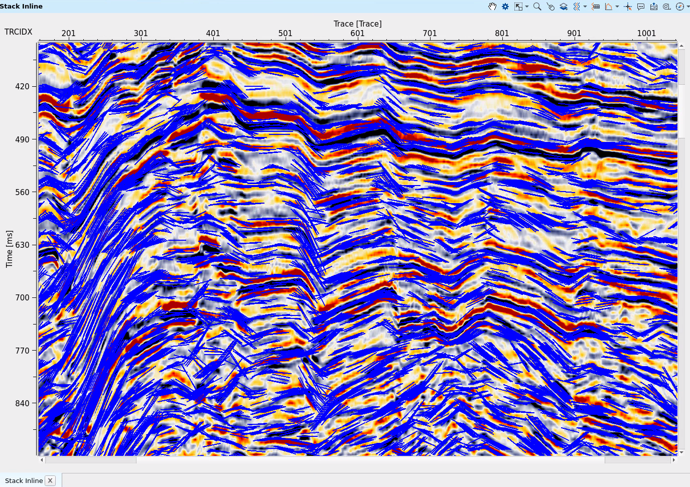
In this example we use stack section that was migrated (PSDM) and converted into time domain, then AGC was applied to it for better signal event ratio. There is Seismic data mode was used for tomo slopes picking:
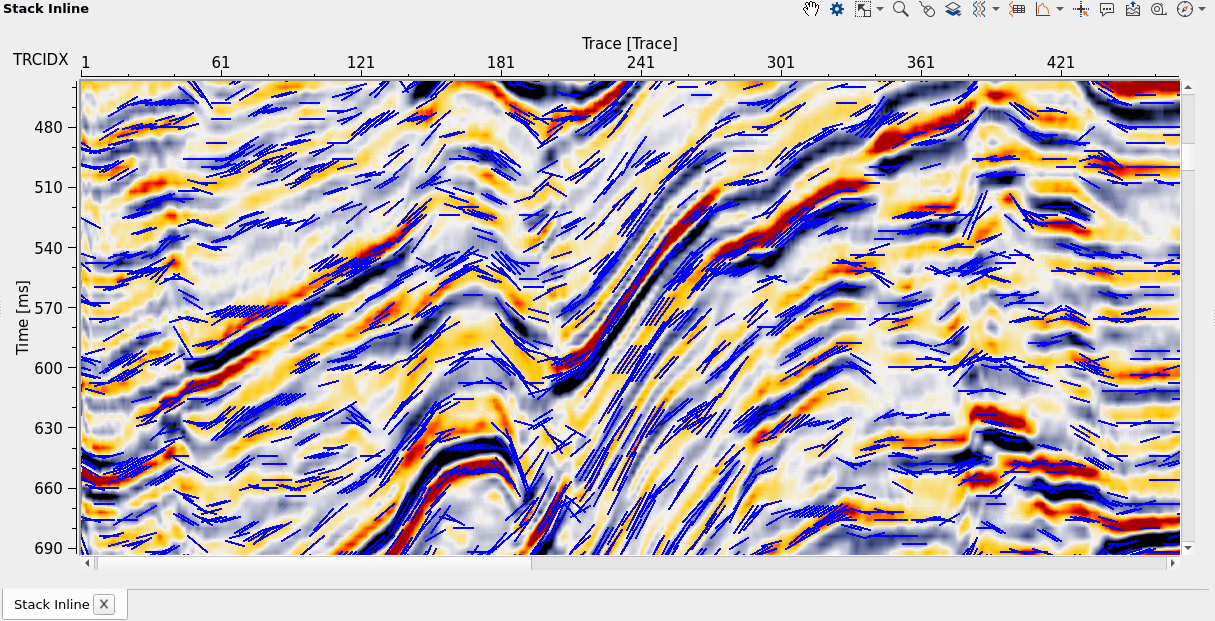
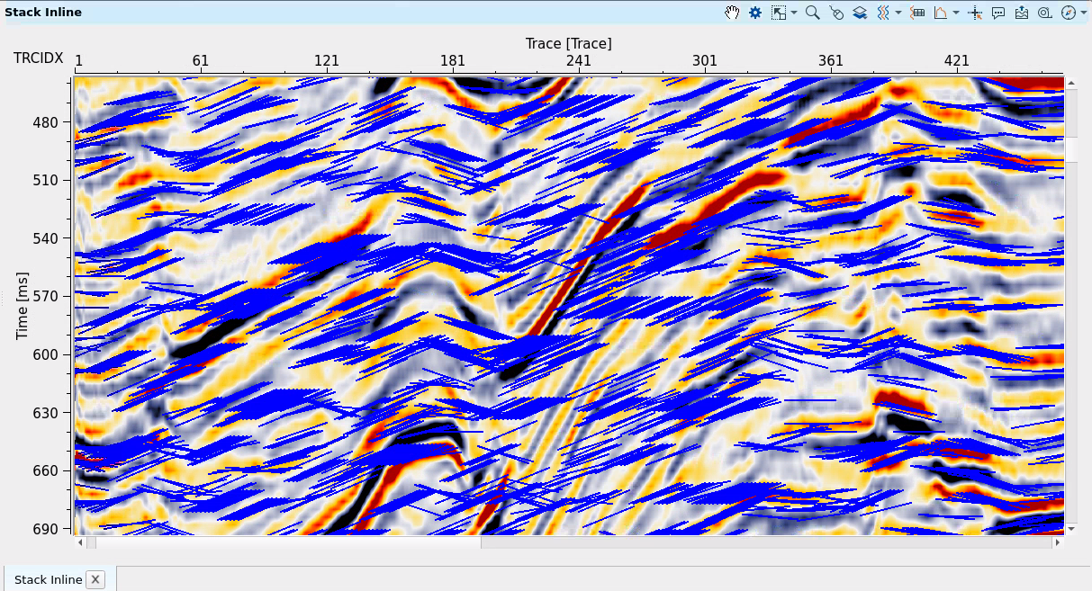
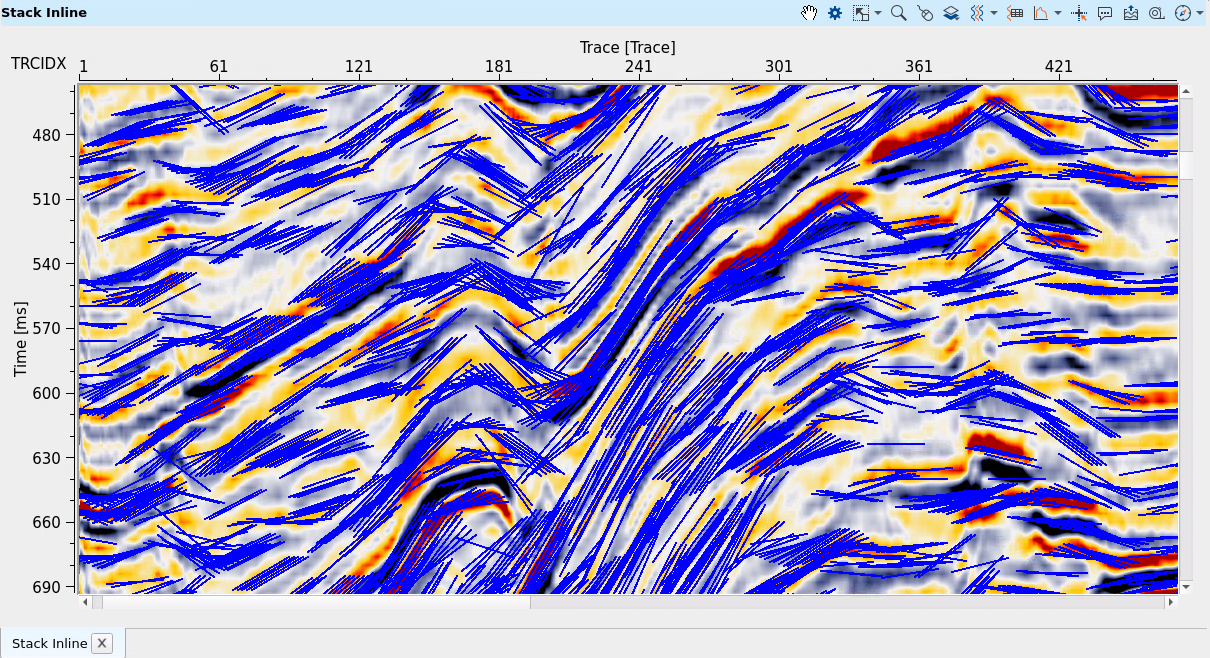
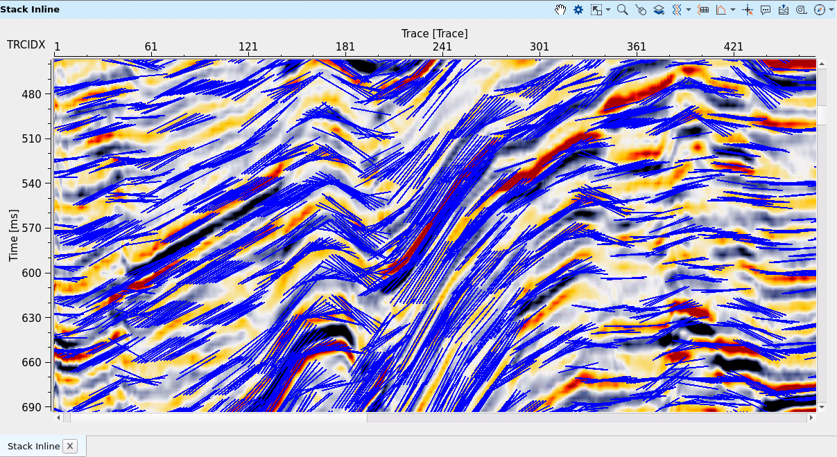
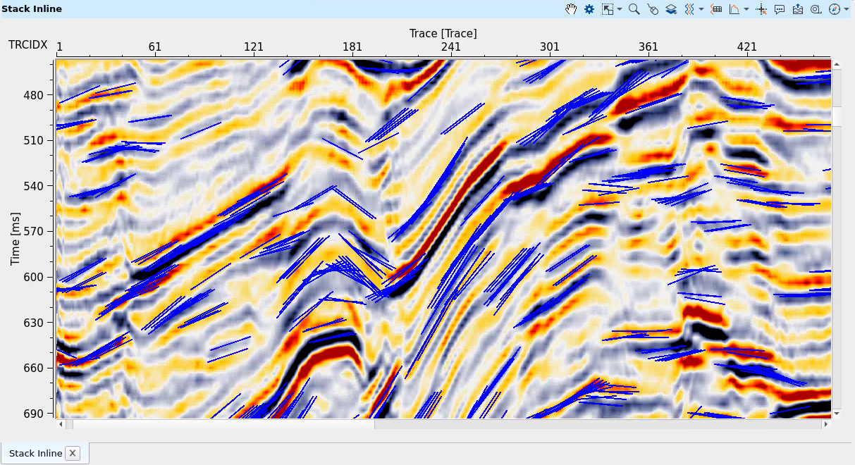
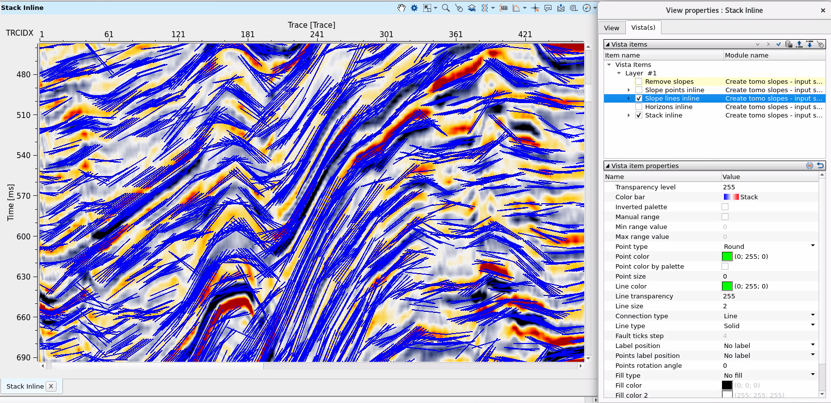
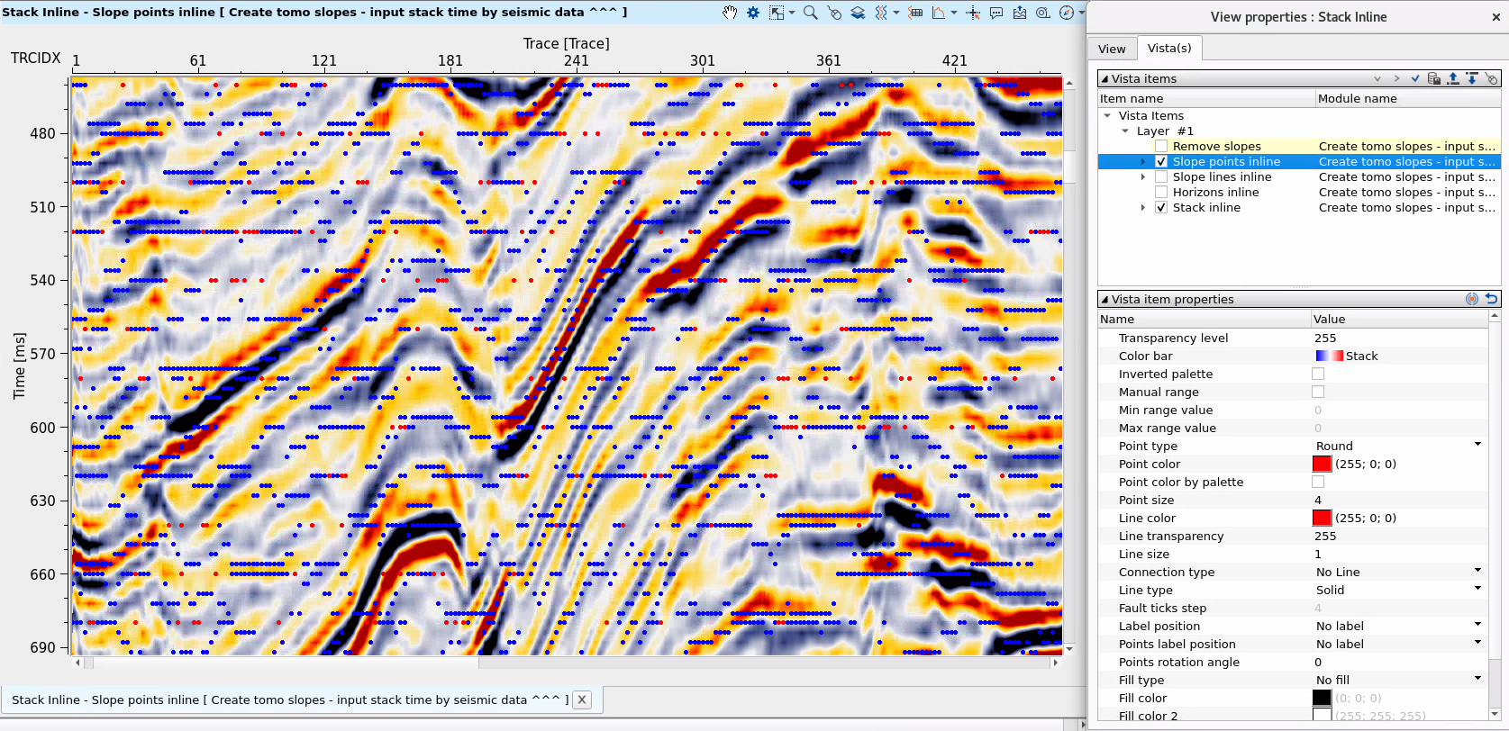
In the visualization windows there is a list of visual layers. 3 of them are pictured below (Slope lines inline, Stack inline, Slope points inline):
SLOPE LINES INLINE - is a slope picking. Therefore there are 2 main layers that are usually used slopes + stack:
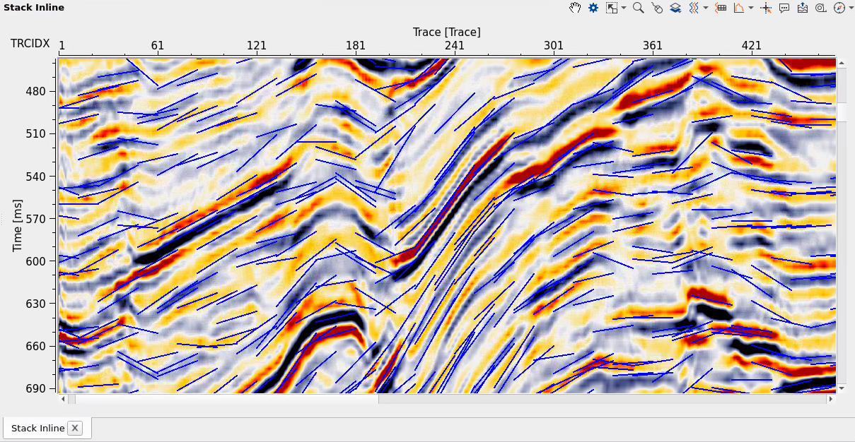
SLOPE POINTS INLINE are extra picks with blue/red colors which means slope was found and slope was not found:
![]()
![]()
 If you have any questions, please send an e-mail to: support@geomage.com