Module name Stack Imaging
Stack Imaging is a very powerful module in g-Platform™ processing suite. It consists of a velocity picking, stacking, mute picking, creating NMO gathers in SEGY format etc. A typical workflow looks like this.
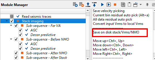
The main advantage of g-Platform™ processing suite is that the user need not to create a separate workflow to apply an AGC or Deconvolution or any processing module, it's just need to simply insert those modules in the sub-sequence of the existing workflow. In this below example, we have added AGC & Deconvolution to the Sub-sequence of Velocity Analysis and Gathers before NMO.
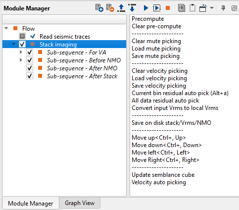
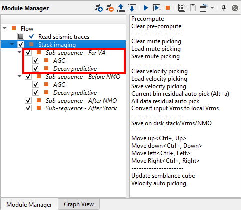
If we look at the action items menu on the right hand side of the Stack Imaging module, the user can see many options to perform in a single module.
In the Parameters tab, we have many options to play with. Stack Imaging does have a sorting method inside the Parameters where the user can sort using their preferred choice.
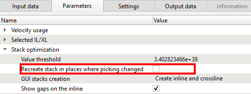
It is also important to mention that, user can recreate the stack only where changes in the velocity picks were made. This feature can be turned on under the Stack optimization and check "Recreate stack in places where picking changed". This way we can generate the stack much faster.
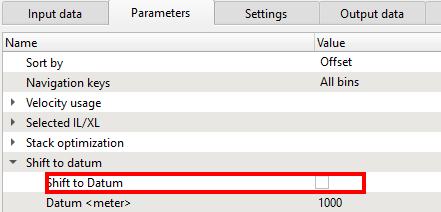
Velocity picking within the Stack Imaging module is not corrected to final datum. In g-Platform, we pick the velocities on the topography and if the user wants to shift to final datum then the user can check the option "Shift to datum " under the "Shift to datum" inside the Parameters tab. Also the user can perform this task by adding the "Shift to datum" module under the Sub-sequence - After stack.
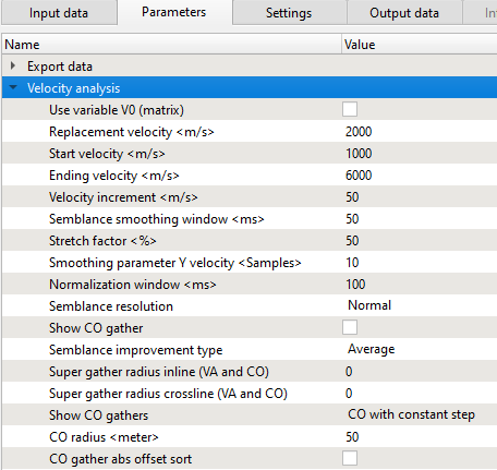
Creation of Velocity semblance and to input the velocity parameters the user should go to Velocity analysis category in the Parameters tab and define the velocity parameters.
Along with the velocity semblance, we can create the mini stacks or CVS (Common Velocity Stacks). This can be achieved by going to the "Mini-stack parametrization". Inside this, we can check the "Create mini stacks" option to generate the mini-stacks. Also we've to define the "Mini-stack trace radius" to determine the size of the mini-stack.
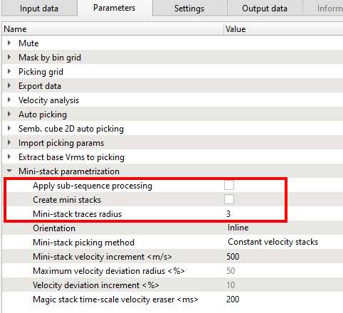
In the case, the user wants to apply the sub-sequence processing then they can check this option as well however it shall give a slight delay in response time to process.
Now we are ready to pick the velocities and create the stack using Stack Imaging module. In order to do that we've to display the vista items. In Stack Imaging, we have few options like 2D groups, 3D groups and All groups.
When the user is working on a 2D line, we would recommend to select the 2D groups option. The main difference between the 2D & 3D groups is that we won't generate the cross line stacks & Vrms sections for 2D group. In this case, we are showing a 2D groups and adjusted the window panels as per our choice.
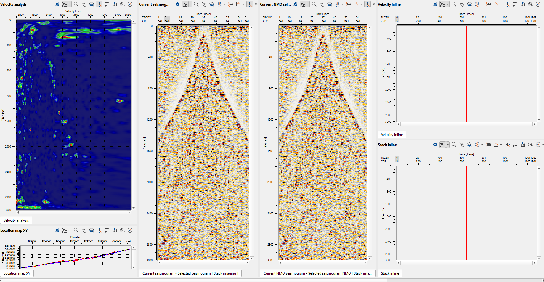
In the above image, we can see the Velocity semblance, Location map on the left hand side, Current seismogram followed by Current NMO seismogram in the middle and Velocity Inline & Stack inline on the right hand side. As we mentioned earlier, the user can rearrange these windows.
Please make a note that mini-stacks are not added to the 2D groups by default. If the user wants to display it in the current workspace, the next should be selected Vista Groups-> Mini stacks-> Add view.
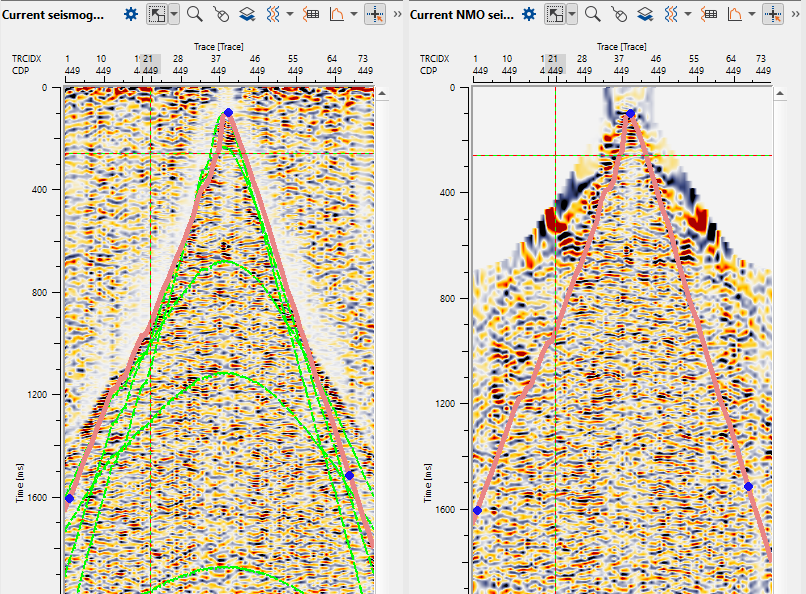
To pick velocities, the user should click on the velocity analysis window panel. It will come up with three lines. The two yellow lines are basically the Velocity corridor and the middle line is the Current velocity pick trend. Once the user start picking the velocities, a red line appears which is the Interval velocity. In the middle of the section, now we can to see the gather before and after NMO correction.
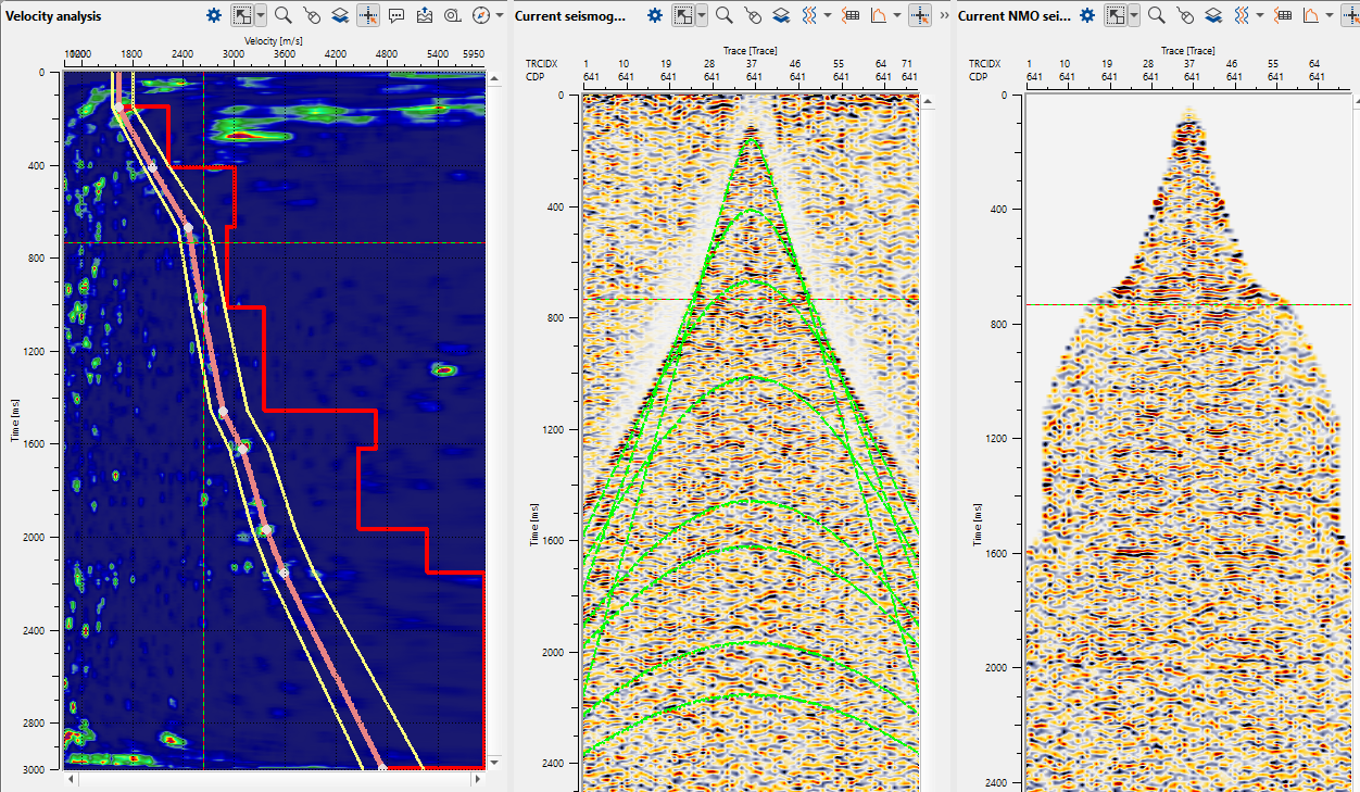
The green lines on the Current seismogram represents the travel time curves. If the user wants to hide them it can be done from the View properties window of the Current Seismogram.
Depending on the user's parameters, we can pick the velocities either randomly by selecting on the location map or as per the picking grid which was defined in the Parameters tab. To move left, right, up & down, one can look at the action items menu and use the short cuts to move around.
To remove any bad picks, the user should hold MB3 or RMB and draw a polygon. Whatever is falling inside the polygon will be removed.
To edit any picks, it should be done by hold MB1 or LMB and drag wherever the user prefers.
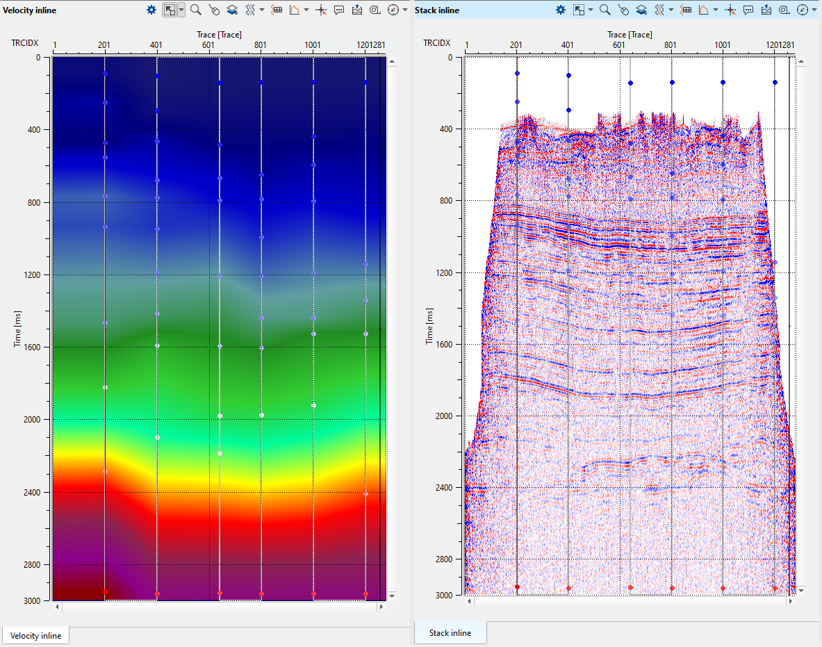
As we are picking more locations, Velocity inline keeps updating however we still won't see the Stack inline. To generate the Stack inline, we should execute the Stack Imaging module.
We mentioned at the beginning of the Stack Imaging module that, this module can be used to pick Mute (CDP domain). To pick a mute on the Current NMO seismogram, click on the gather and it should come up with the mute lines. These mute lines are visible on both Current seismogram & Current NMO seismogram.
To remove the picks, it is similar to the velocity picks where the user should hold MB3 or RMB and draw a polygon. As soon as the user release the mouse, it will remove the pick. To move the picks, it should be MB1 or LMB.
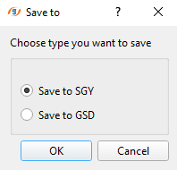
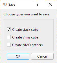
Also we mentioned at the beginning that the user can create the Stack/Vrms/NMO from the Stack Imaging module. In order to create and save them, we should choose the option Save on disk stack/Vrms/NMO from the action menu. As soon as we click the option, a pop-up window opens with default option "Save to SGY". Click OK. Now another pop-up window opens up with different options. Here the user can select one or all of them and click OK. Finally a file browser window opens and here the user should provide a name. Depending on the choice of user selection, it will suffix the names to the respective data type with an extension of SGY to the dataset.