 | DATUM PLANES |
|
<< Click to Display Table of Contents >> Navigation: Tutorials > Seismic Processing 2D LAND >
|
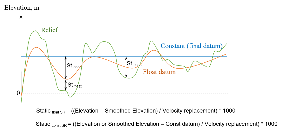
Land seismic acquisition requires to use seismic datum plane (DP), because relief is variable and it may produce incorrect velocity estimation. There are two common types of datum planes: constant and float. Float datum plane usually is used in case of high variations in elevations, so it means we can't use a constant datum due to the fact that velocity estimation should be accurate. But if we use a constant datum plane in case of big fluctuation of topography we may loose details in RMS velocity during NMO spectrum analysis. Float datum is a smooth tomography of sources and receivers elevations (smooth aperture usually is 500-1500m). Therefore, if we have quite flat relief it is reasonable to use constant datum plane which is usually just an average level of elevations. Constant datum plane is a level that may be average elevation or be above the highest elevation. Static corrections move data to the datum with using replacement velocity (Vrep), and it is an acoustic velocity value used during processing for static calculation in order to bring data to a desired level (const of float).
A few basic points:
•Binning 2D/3D modules create a smooth topography (float datum) and save it into BIN_ELEV header;
•After NMO-correction seismic data will be shifted to the floating datum (NMO module calculates and applies static shift automatically);
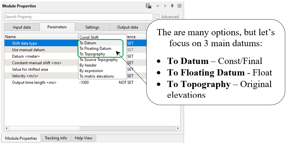
•Shift data module moves seismic data to any datum: constant/final, floating or topography;
•Read SEG-Y traces module does have Data datum parameter. We must set datum correctly, for example if data is on topography, set Topography.
g-Platform system provides all necessary options for datum planes:
•Topography (relief);
•Float (smoothed topography);
•Final (constant).
When you read SEG-Y file, there is an option for defining datum plane, look at the parameters of Read SEG-Y traces module and find Data datum:
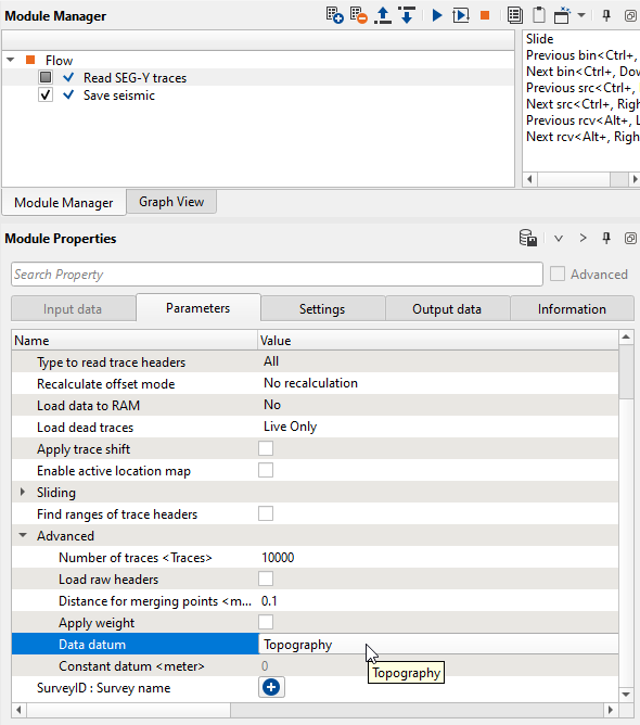
If the input seismic data set is on topography we should choose Topography option.
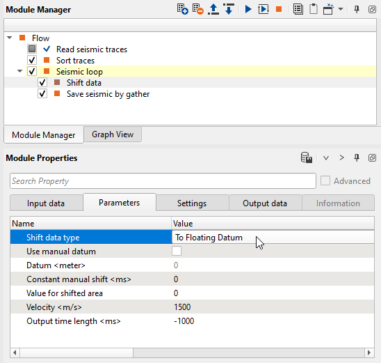
During geometry assignment process, we can create a smoothed topography which is actually representation of the floating datum. Values of floating datum are written into trace headers and we can use it for static calculation via Shift data module. In case of shifting data to the float datum we need to choose To Floating Datum option and define replacement velocity - Velocity <m/s>. Look at example of workflow:
Current chapter is about theoretical aspects of datum planes in g-Platform and we are not going to apply any static correction here.
--------------------------------------------------------------------------------------------------------------------------------------------------------
![]() We will use topography datum plane before NMO correction in this 2D land tutorial.
We will use topography datum plane before NMO correction in this 2D land tutorial.
After NMO-correction the seismic data will be on floating datum.
Module NMO calculate static correction and apply it automatically. The NMO module uses following
headers for calculation: BIN_ELEV, SOURCE_ELEV, RECEIVER_ELEV, replacement velocity is
defined in the module's parameters. SOURCE_DATUM and RECEIVER_DATUM headers will be updated.
In Binning 2D module, we provided created a smoothing topography which is representation of the floating datum.
---------------------------------------------------------------------------------------------------------------------------------------------------------
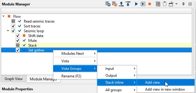
Let's do some tests with datums. Firstly, create a new temporary workflow in your project and open it. We will build 3 stacks with different datum planes (topo, float, const/final). Add all necessary modules as shown below:
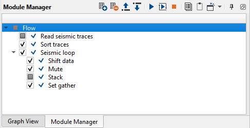
1. Read seismic traces
2. Sort traces
3. Seismic loop
4. Shift data
5. Mute
6. Stack
7. Set gather
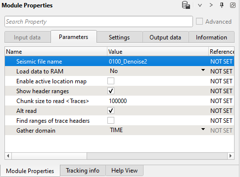
1. Read seismic traces. Define the input seismic file parameter 0100_Denoise2.
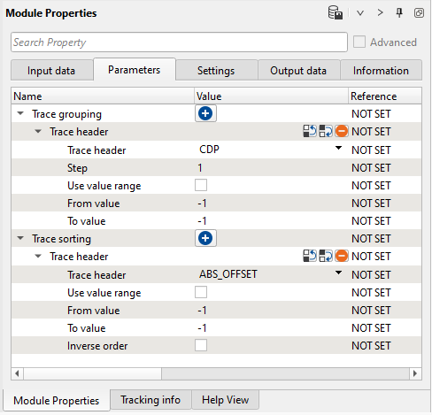
2) Sort traces. Connect the input vector with trace headers from the previous module and add one sort header CDP, ABSOFFSET. It is required for the Seismic loop module:
3) Seismic loop. Connect input vector (Input DataItem) with trace headers and seismic data from the previous module, it automatically gets sorted headers from Sort traces and seismic traces from Read seismic. Launch Read seismic traces and Sort traces. Put the following modules inside Seismic loop: Shift data, Mute, Stack, Set gather.
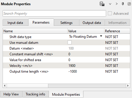
4) Shift data allows to use various types of datum planes, i.e. it shifts seismic data to the desired level: topography, float, constant/final.
Parameters:
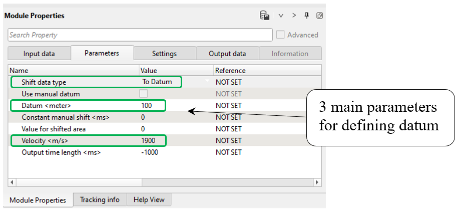
First test with option To Datum, so choose this one, define datum parameters:
•Shift data type = To Datum (constant/final)
•Datum = 100 m (constant level)
•Velocity = 1900 m/s (replacement velocity)
-------------------------------------------------------------------------------------------------------------------------
![]() Normally, don't use Use manual datum option. This is an auxiliary parameters for changing
Normally, don't use Use manual datum option. This is an auxiliary parameters for changing
datum value of the input data.
-------------------------------------------------------------------------------------------------------------------------
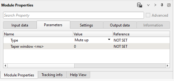
5) Mute. Create a mute function for a stack and define parameters:
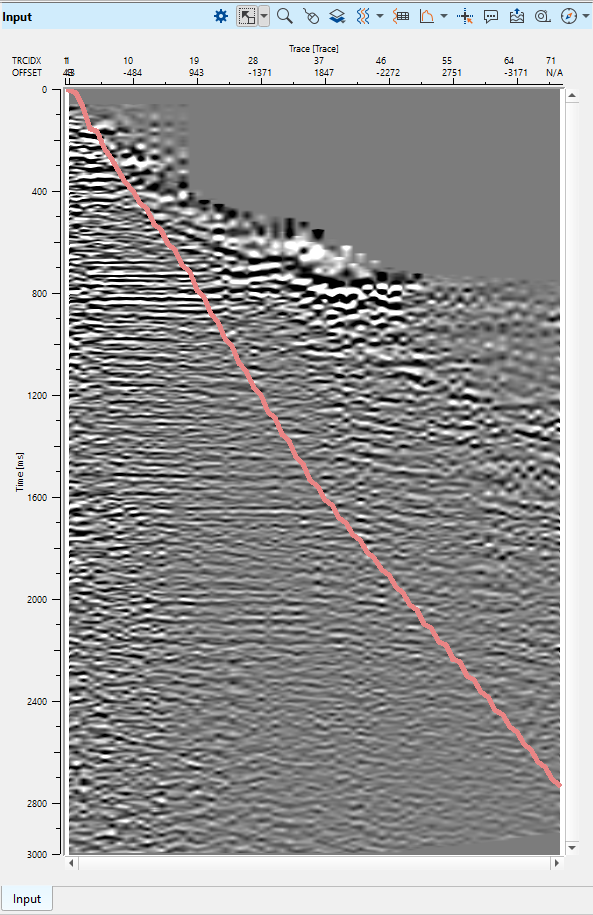
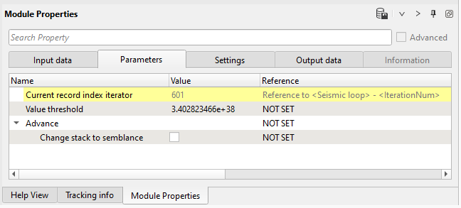
6) Stack. This module calculates stack. For each gather it calculates sum of traces and divide by number of non-zero traces in the gather. Use default parameters:
7) Set gather. This module gets traces and accumulates it in to a single gather. For example we try to compute stack in loop and necessary to view resultant stack on a screen.View after module Stack will produce only one trace, but we need a full stack.In this case we can use module Set gather to accumulate our stack for visualization. Execute the entire seismic loop to create a stack.
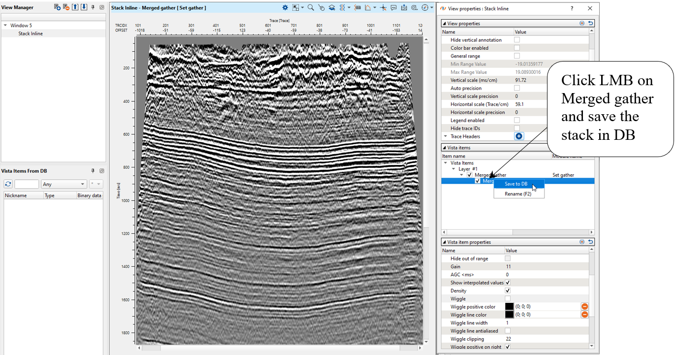
Open stack vista view:
Save resulting stack section in DB:
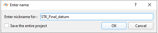
Define an output file name STK_Final_datum:
Change datum parameters from constant to floating datum and create a new stack and save it to DB with name STK_Float_datum.
Shift data parameters:
Compare two stacks via overlaying option: use drag'n'drop function to get stacks from DB:
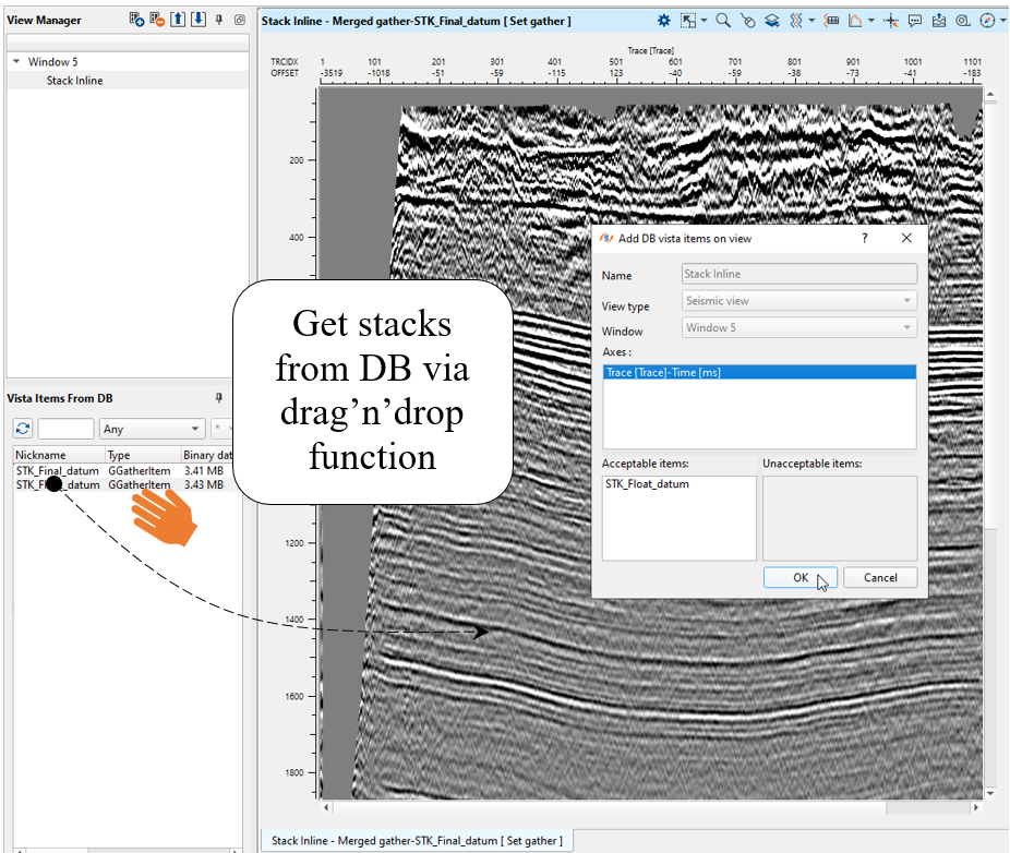
Compare two stack via overlay function:
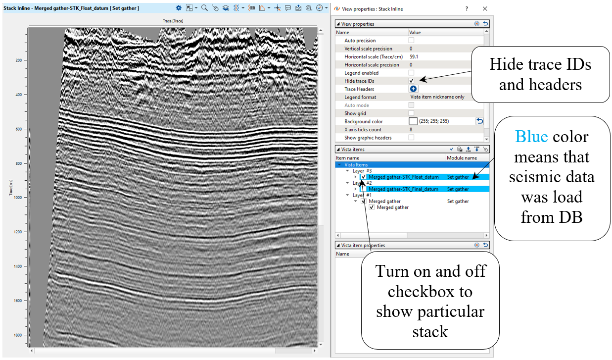
Pay attention that it is just test for learning how to use datums in g-Platform. Wherefore, don't shift data, we can work from topography. Of, course, stacks will be on constant/final datum, but gathers on topography.
Next step >>> Refraction static correction.
 If you have any questions, please send an e-mail to: support@geomage.com