 Depth Migration (PSDM)
Depth Migration (PSDM)
|
<< Click to Display Table of Contents >> Navigation: Tutorials > Seismic Processing 2D MARINE >
|
This module performs 2D/3D time migration of seismic traces before stack. The algorithm is a Kirchhoff integral trace migration where each sample is considered the top of coherent events of a diffracted wave followed by stacking the samples. In other words, Kirchhoff migration estimates diffracted amplitudes by correlating the input seismic data using a calculated model of the diffraction as it would appear if the image point consisted of a diffraction event. All dip and diffraction events are migrated into their real location. Diffraction waves are described by RMS velocities.
The migration process is run in offset classes (user-defined parameters) and requires regularized input seismic data (that can be produced using the Regularization module). Gaps in the offset classes can cause migration operator artifacts. This module reads input seismic data directly from disk and it is unnecessary to load it to RAM. Input seismic data are CMP gathers. Output data are common image gather - CIG. Execution options: standalone (1 computer execution) and remote (parallel/cluster execution).
------------------------------------------------------------------------------------------------------------------------------------------------
![]() Notice that version of the g-Platform used for PSDM chapter is 5.24167, so all parameters, options, visual QC windows and results may be different from your version.
Notice that version of the g-Platform used for PSDM chapter is 5.24167, so all parameters, options, visual QC windows and results may be different from your version.
------------------------------------------------------------------------------------------------------------------------------------------------
Create a new workflow 0230-pre-stack-depth-migration:
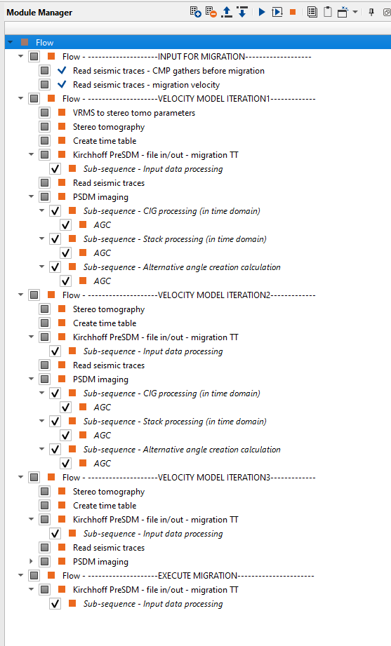
-------------------------Please inert image here------------------------------
Kirchhoff PreSDM - file in/out - migration TT
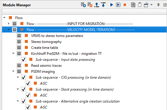
The entire workflow looks a bit complicated, but it is not actually ;-) add all these modules to your workflow:
A basic scheme of the PSDM process:
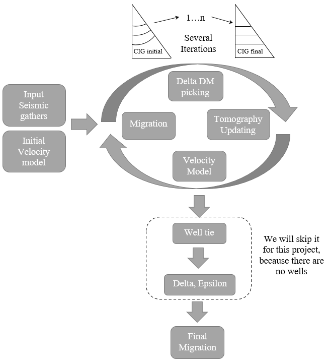
Current project does not have wells, so we have to skip well tie and Delta+Epsilon calculation steps. Therefore, we have only 3 main parts:
1.Prepare seismic data for velocity analysis;
2.Velocity analysis;
3.Migration execution (Pre-Stack Depth Migration);
INPUT FOR MIGRATION
Load seismic data and velocity for further velocity analysis:
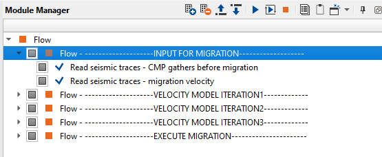
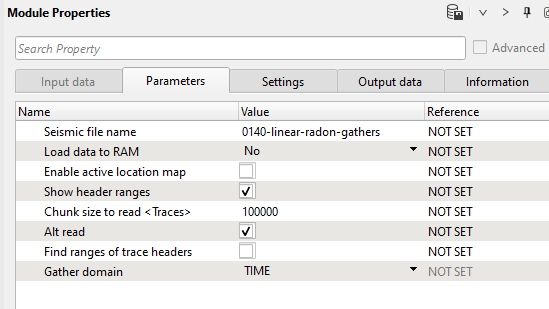
1) Read seismic traces - CMP gathers before migration. Load gathers that were prepared for migration step earlier (no NMO): 0140-linear-radon-gathers:
Parameters:
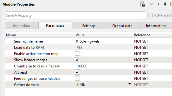
2) Read seismic traces - migration velocity. Load velocity after Pre Stack Time Migration 0150-mig-vels into RAM:
Parameters:
VELOCITY MODEL ITERATION 1
Part of the workflow for the 1st iteration of depth migration: velocity model building:
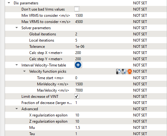
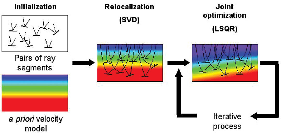
3) VRMS to stereo tomo parameters. We can use PreSTM velocity to create an initial stereo-tomographic model. The stereo-tomographic model is a velocity macro-model with a set of pairs of ray segments associated with each picked event such as the ray shooting angles from event towards some source and receiver and corresponding two one-way travel times.
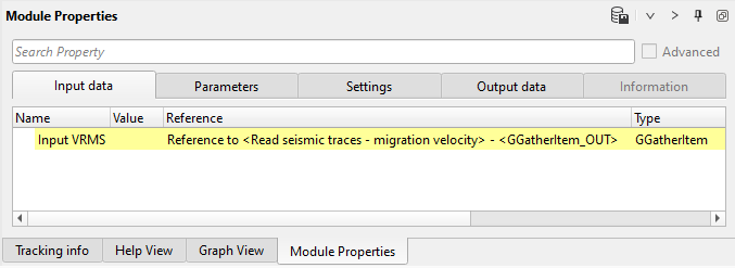
Connect input Vrms from the read Seismic traces module - migration velocity:
Input data:
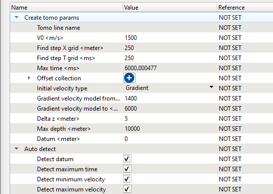
Define the parameters V0, cell sizes, velocity limits and others. Execute the module:
Parameters:
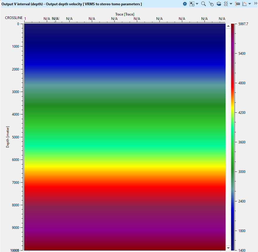
Execute the module and open vista view window and check the output interval velocity:
4) Stereo tomography creates a depth velocity model from VRMS. Stereo tomography is based on Ray tracing algorithm. The basis of the Stereo Tomography concept is to recognize any locally coherent events characterized by their travel times and local slopes (two slopes) in the pre-stack data to provide some information about velocity model. The locally coherent events can be interpreted as pairs of ray segments and provide the velocity information independently. This module is used to generate the updated velocity models. We generate the Tomo items from the VRMS to stereo tomo parameters or PSDM Imaging modules. Within the PSDM imaging module, we have Create tomo parameters action items (use action menu) and it will create the tomo item for Stereo Tomography as an input.
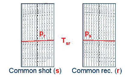
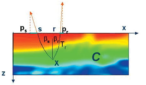
A stereo tomographic data set consists of locally coherent events parametrized by source & receiver positions, travel time and slopes of the events in the common shot and receiver domain. The basic scheme of stereo-tomography:
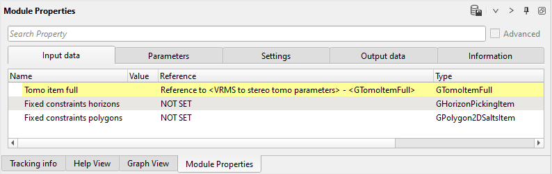
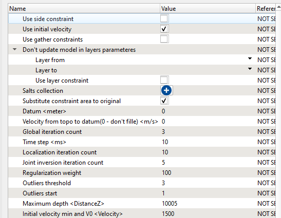
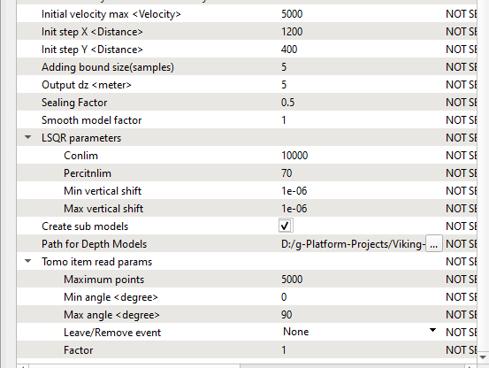
Get Tomo item full from the VRMS to stereo tomo parameters, define the parameters and execute the module:
Input data:
Parameters:
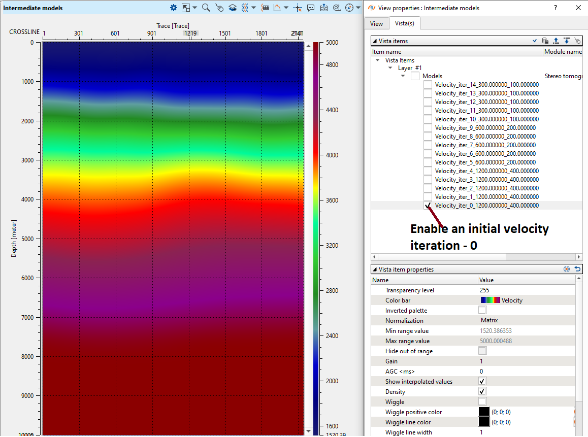
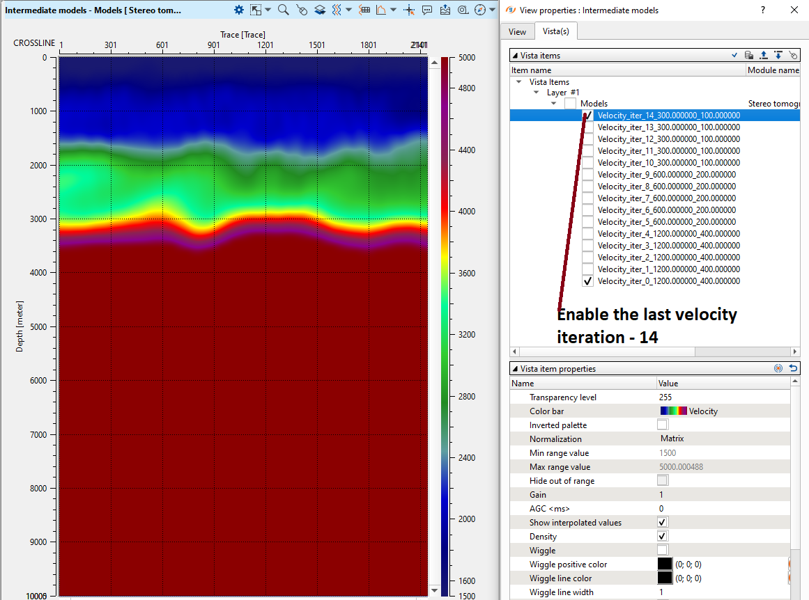
Open vista view windows and check the updated interval velocity, as well as some additional QC attributes. First, look at intermediate models:
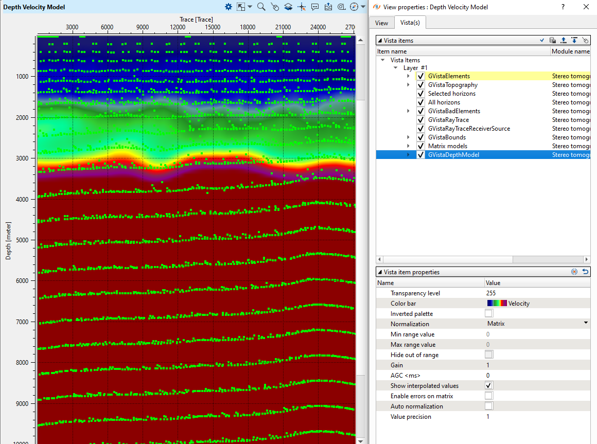
Go to the Depth Velocity Model:
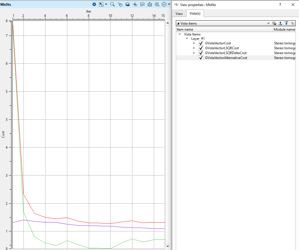
Analyze the misfits graphs of cost function to understand how many iterations would be enough for velocity updating:
5) Create time table module calculates time table for depth migration. This table contains information about all possible wave travel times from one model cell to neighboring. These tables are calculated based on the velocity model and are required to calculate depth migration.
Get Depth velocity item from the Stereo tomography module and define an output file name for time table 0220-tt-itr1:
Input data:
Define the parameters for time table calculation as shown below:
Parameters:
Execute this module.
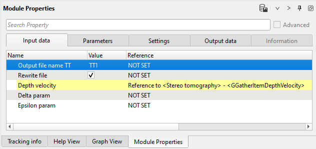
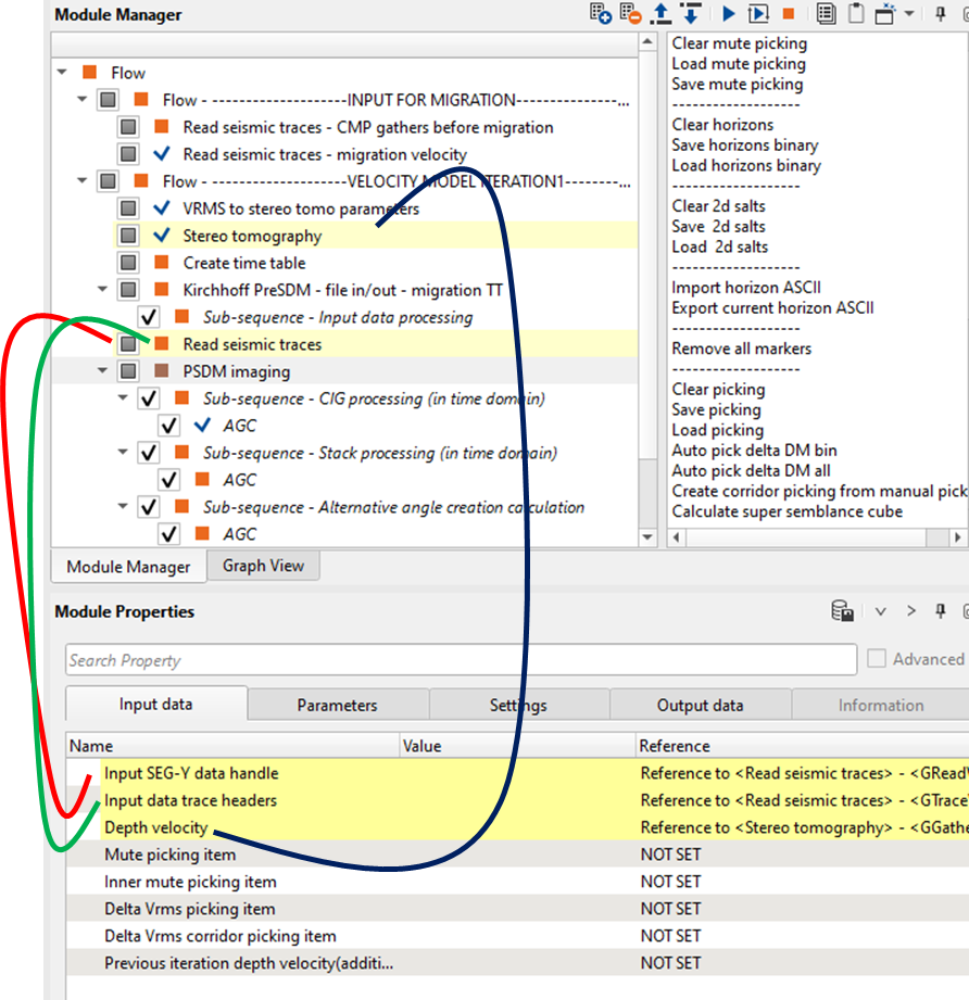
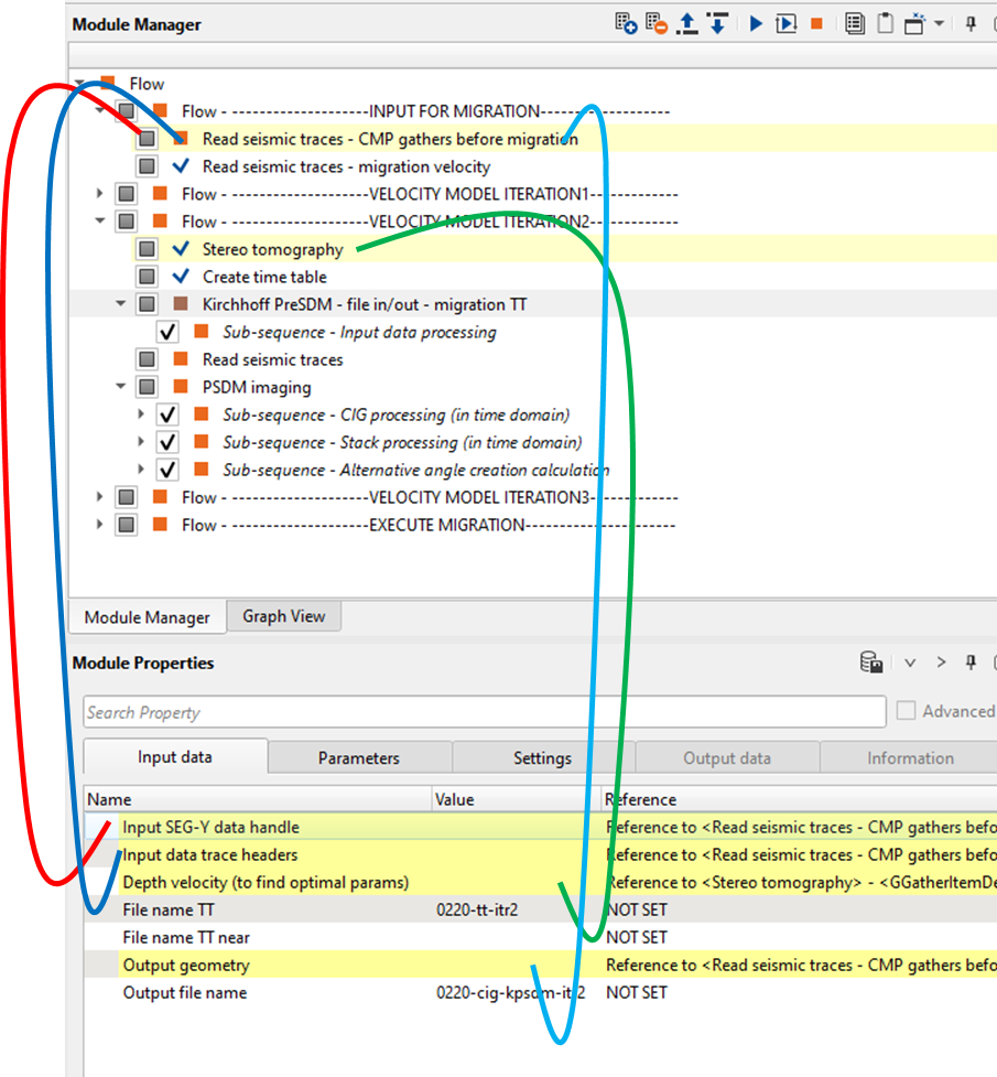
6) Kirchhoff PreSDM - file in/out - migration TT. This module performs depth migration by using depth velocity model from Stereo tomography and time tables from the Create time table. Define an input data and parameters:
Input data:
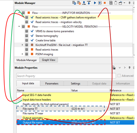
In the above image, we need to select the File name TT from drop down menu. We must provide the Output file name also which is shown in dotted red rectangle.
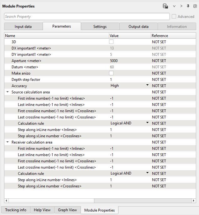
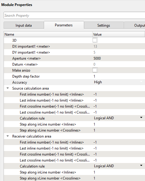
Parameters:
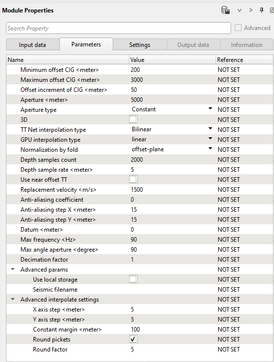
Basic parameter's definition:
Input (what we need to provide):
1. Input to the PreSTM gathers or COMF enhanced gathers for generating the PreSDM CIG (Common Image Gathers)
2. Stack or velocity volume for mapping the trace headers
3. Travel time table
4. File name TT near (If the user chooses the option "Use near offset TT"). This is not mandatory but the rest are mandatory.
Output (what we get): PreSDM CIGs.
Minimum offset CIG
Provide the minimum offset for generating the CIG output.
Maximum offset CIG
Maximum offset for generating the CIG output.
Offset increment of CIG
Step size of offset increment.
Aperture
Migration aperture.
Aperture type
Select either Constant or Depth variant (If the user chooses Depth variant then they should provide different apertures at different depth intervals).
3D
In case of 3D, check this option.
TT Net interpolation type
Travel time net interpolation type. We have two options. Bilinear and Nearest.
If there are two traces within a constant grid spacing and if any bin falling in between these two traces then the user can select Bilinear option to do the interpolation. The interpolation is simply a linear one.
If the user chooses Nearest then the trace which is nearest to the bin will be considered in the interpolation.
Normalization by fold
Depending on the option, normalization of the amplitudes takes place. For example if the user selects the "trace", then it will calculate the number of curves/wavefronts intersect that particular trace and accordingly it will normalize the amplitude of that particular trace. Similarly if the user chooses "sample" then for each sample how many wavefronts intersected that particular trace at that particular sample and normalizes the amplitude.
Depth samples count
Specify the number of depth samples. i.e. up to what depth the user wants to migrate the data with respect to depth sample.
Depth sample rate
Mention depth sample rate.
Use near offset TT
In case the user wants to image the near offsets only then they can check this option. For this, the user should provide the near offset Time travel tables in the input (File name TT near). In such cases, the user should calculate the travel times for near offsets only.
Replacement velocity
Provide the replacement velocity information.
Anti-aliasing coefficient
Choose between 0 and 1. Zero means no anti-aliasing.
Datum
Provide the datum information. As we mentioned at the beginning of this manual, unlike the PreSTM where we migrate the data from the topography, here we need the datum information in order to do the depth imaging.
Max frequency
Provide the maximum frequency to include the imaging process.
Max angle aperture
Provide the maximum angle.
Decimation factor
This will be helpful while doing the testing to optimize the parameters and for quick turn around time.
Use local storage
This option is useful when the work flow executed in a cluster environment where we can assign save the output in local disk for better I/O.
Seismic filename
Provide the file name in the local disk.
Execute this module. There is no any output vista windows, so you need just execute this module to get data after 1st iteration of depth migration (CIGs).
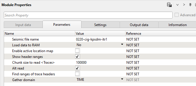
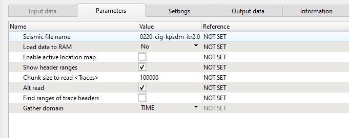
7) Read seismic traces. Read migrated CIGs after Kirchhoff PreSDM - file in/out - migration TT.
Parameters:
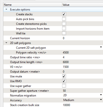
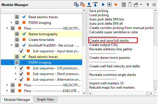
8) PSDM Imaging performs various functions like updating the velocity model, picking the delta Vrms via the Delta Vrms semblance for correcting/flattening the gathers, mute picking on the CIG gathers, creating output CIGs, building final stacks and so on.
Firstly, we need to get already prepared seismic data set (migrated CIGs).
Inputs:
1. PreSDM CIGs
2. Velocity model
Outputs:
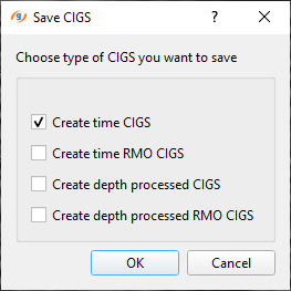
1. Time CIGs
2. Time RMO CIGs
3. Depth processed CIGs
4. Depth processed RMO CIGs
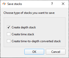
5. Depth stack
6. Time stack
7. Time to depth converted stack
8. Angle stack
Input data:
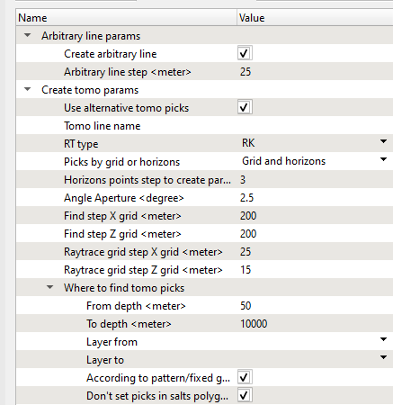
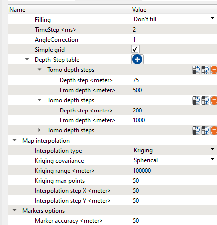
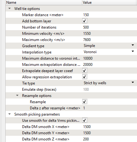
Parameters:
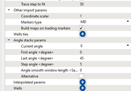
---------------------------------------------------------------------------------------------------------------------------------
![]() This module can work with geo-bodies like salt, i.e. we are able to create a polygon for salt body, define velocity for it and use this information during migration process. See module's doc.
This module can work with geo-bodies like salt, i.e. we are able to create a polygon for salt body, define velocity for it and use this information during migration process. See module's doc.
---------------------------------------------------------------------------------------------------------------------------------
Execute the module and open vista groups and remove some windows that we are not going to use here. You should have the following list of visual windows. Make all visual setting and window configuration as you wish or try to make the same setup as shown below:
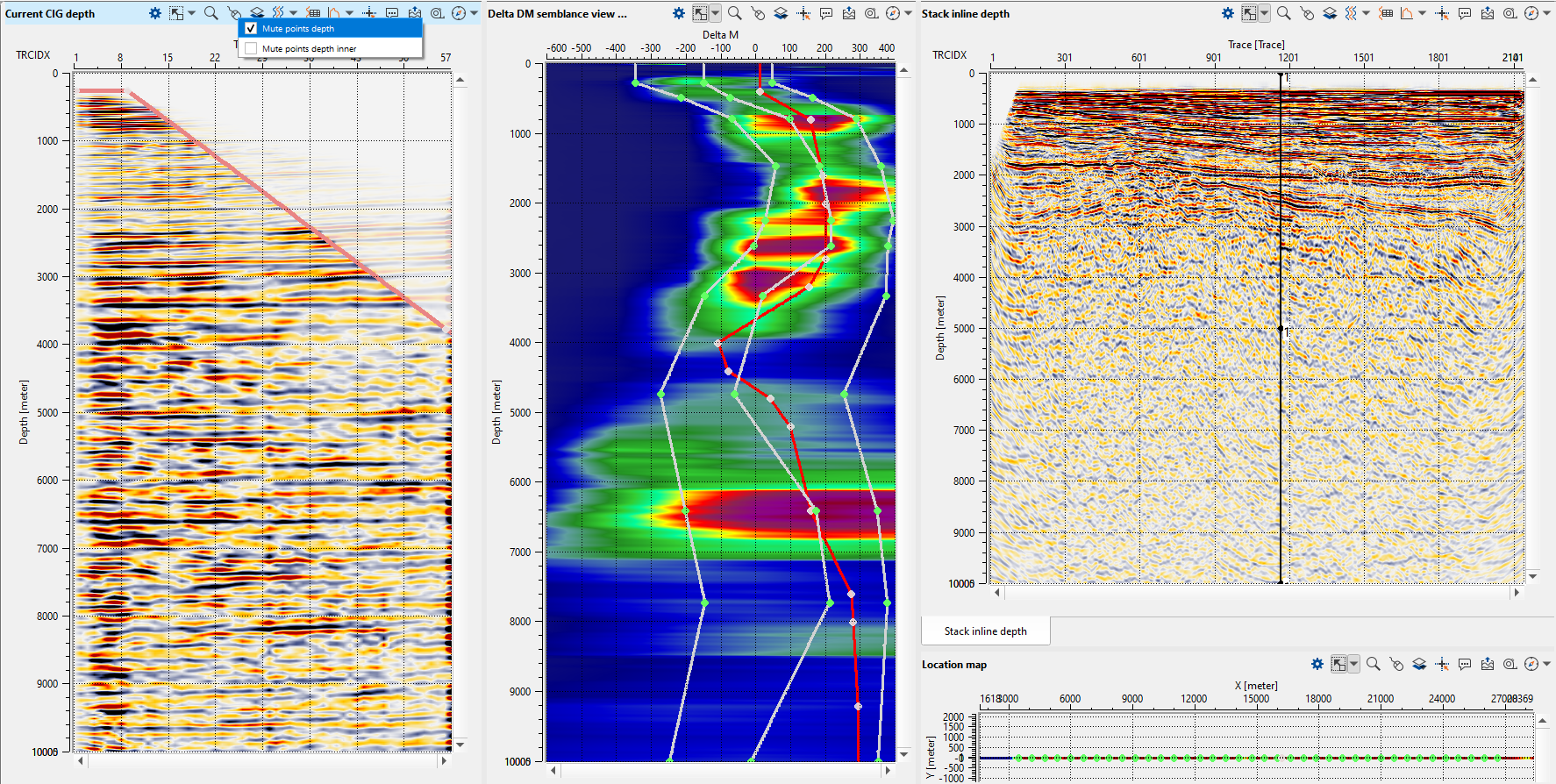
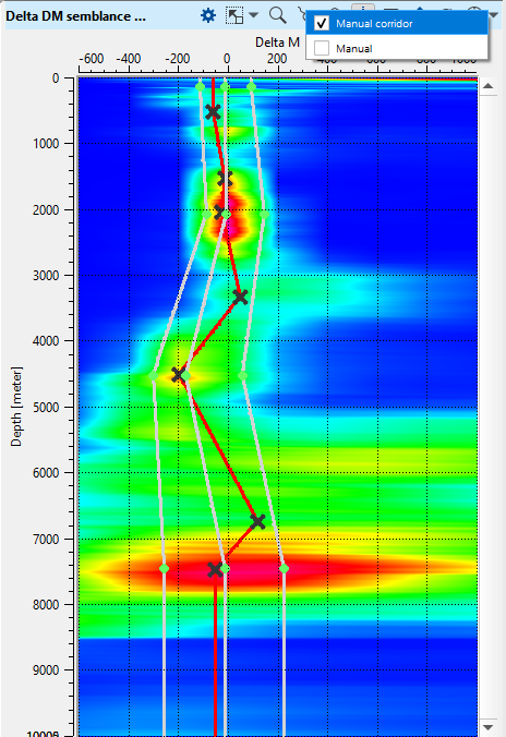
Use Current CIG depth vista to pick outside mute and rerun the module. Now you should get a depth stack without migrations stretching. Now we can begin velocity picking, choose any CIG point on the location map and other windows will be updated automatically. So, activate Delta DM semblance view, choose Manual corridor in set control item and pick it along a line.
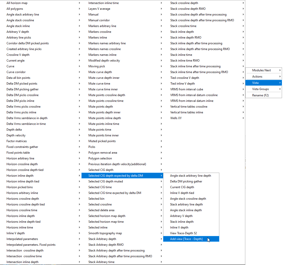
Use Selected CIG depth expected by delta DM for on-fly picking QC: you will see gather after correction. Is you don't have this vista, just add it manually: click RMB on the module and select the Vista:
Now we can see the result of picking without re-run PSDM. gather before and after. Pick all the line as you prefer, for example we can pick every 60-th CIG point (1500 meters step).
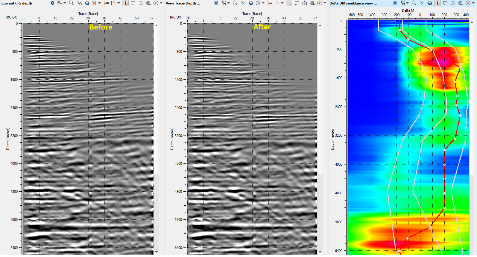
In case of one 2D line we a manual velocity picking is reasonable, but the module provers a auto picking as well. So, we will do a manual picking for the 1-st iteration and auto picking for further iterations.
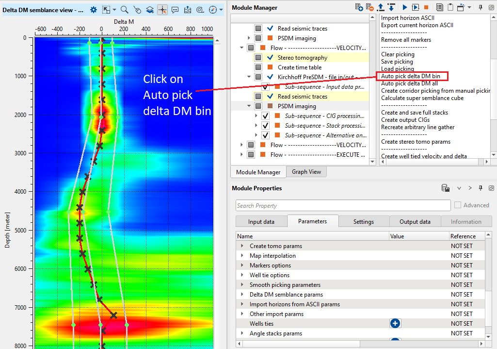
Now we have Delta DM picking and it is possible to calculate the tomo parameters which are used for velocity model updating on the next step. Run tomo params calculation in action menu:
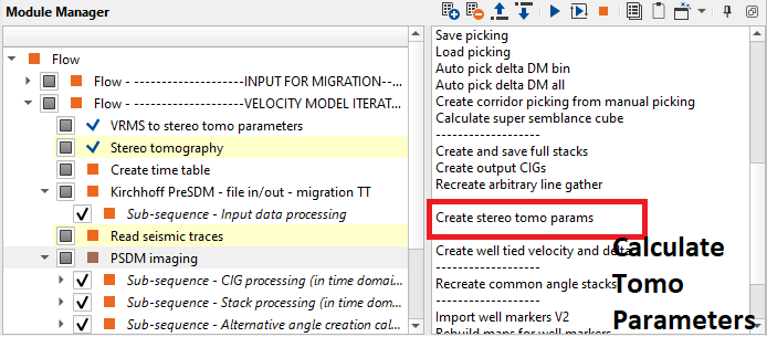
VELOCITY MODEL ITERATION 2..n
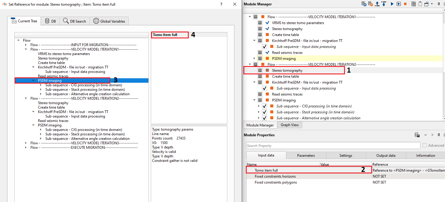
9) Stereo tomography. The second iteration of the depth migration uses a depth velocity model from the first PSDM imaging module.
Connect the Tomo item full from the PSDM imaging:
Input data:
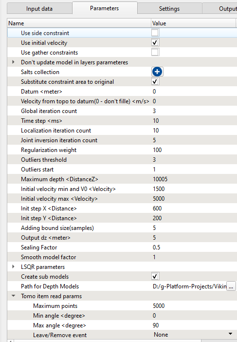
Get Tomo item full from the VRMS to stereo tomo parameters, define the parameters and execute the module:
Parameters:
Execute the module and check the result, if updated velocity model is acceptable we can continue.
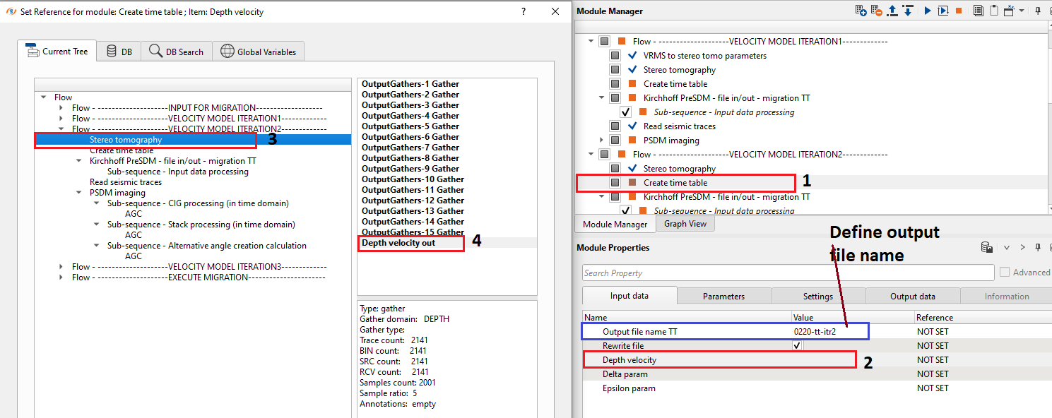
10) Create time table. Use Depth velocity from the second Stereo tomography. Get Depth velocity item from the Stereo tomography module and define an output file name for time table 0220-tt-itr2:
Input data:
Define the parameters for time table calculation as shown below:
Parameters:
Execute this module.
11) Kirchhoff PreSDM - file in/out - migration TT. Define input data as show on picture, use same parameters as the first iteration and run the module:
Input data:
Use the same parameters from the previous iteration.
12) Read seismic traces. Read DCIGs after Kirchhoff PreSDM - file in/out - migration TT.
Parameters:
13) PSDM imaging. At the second and next iterations of depth migration you just need to repeat all steps from the fist iteration to get updated velocity model and Tomo item. Next, use this model for further iteration in the same manner as the previous step. After each depth migration iteration you should get CIG data set with more flattered events and better image of a stack. Stop depth velocity updates after receiving CIG with flat events and DM semblances spectra close to zero value. Usually, we need to run 3-4 iterations if there is a simple geology, in case of complex geology it is required to apply more iterations to get accurate velocity model.
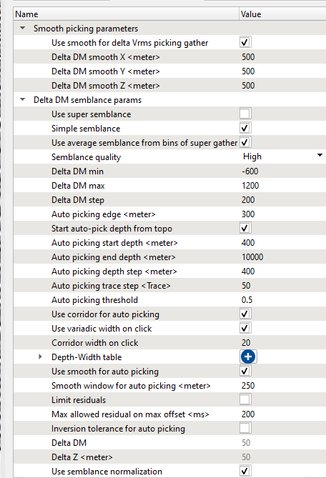
We will use auto picking (Delta DM).
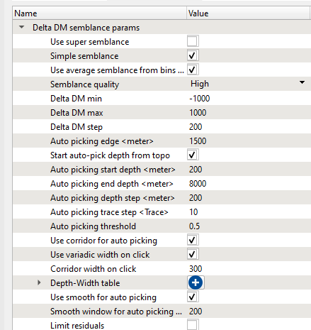
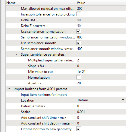
Change parameters that are responsible for auto picking and smoothing as shown below, other parameters are the same as previous:
Parameters:
Open necessary vista windows, usually CIG gather (before and after) and Delsta DM spectrum. Make a corridor picking for auto-picking constraining:
Run 1 bin auto picking:
If you satisfied with the test result for 1 bin/CIG, you can run auto picking for the entire data set by clicking on Auto pick delta DM all option in action menu.
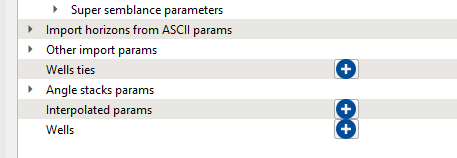
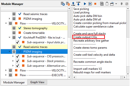
At any point, the user wants to create the CIGs or Stacks, we can do it by simply go to Action items menu of PSDM Imaging module and select the respective options provided to us as shown below.
There are QC of CIGs and depth stack sections after 3 iterations
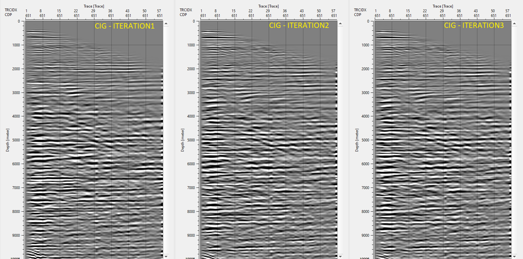
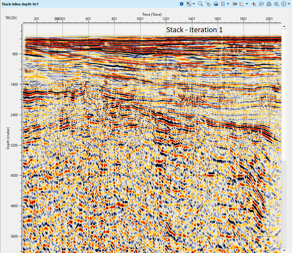
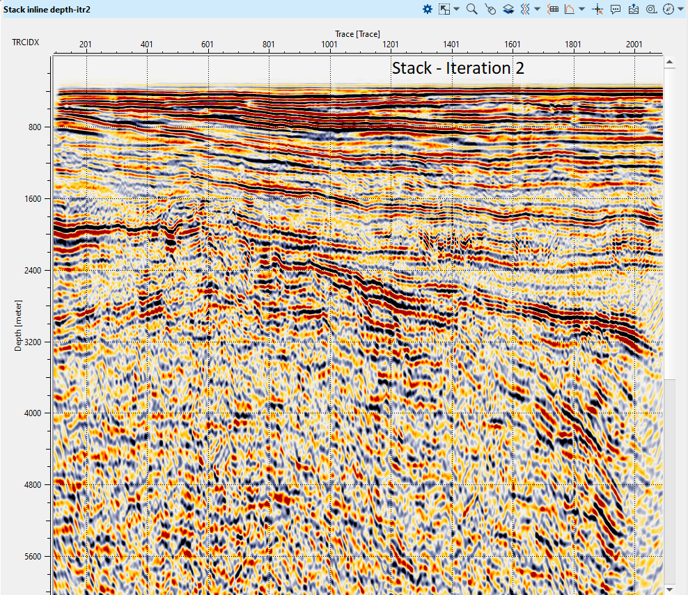
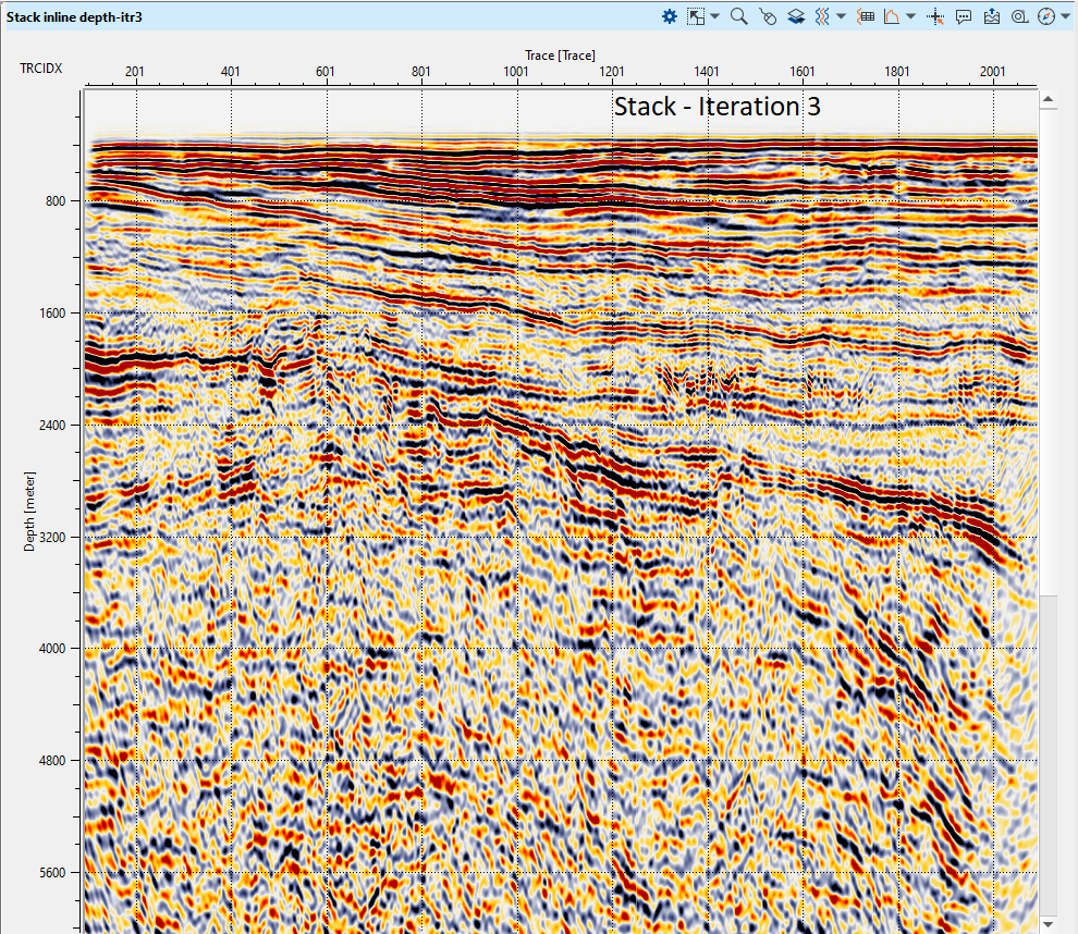
Repeat a few iteration of velocity model building and execute final PSDM process. Review the results from the different iterations and choose the best among them and execute the final PSDM to generate the CIGs.
 If you have any questions, please send an e-mail to: support@geomage.com