 | MULTIPLE ATTENUATION (ITERATION 1) |
|
<< Click to Display Table of Contents >> Navigation: Tutorials > Seismic Processing 3D LAND >
|
The first iteration of multiple attenuation should be not very harsh, because the second iteration will be after migration step due to the fact that multiples are focused after PSTM/PSDM process. g-Platform provides several radon modules and we are going to use Radon multiple attenuation by velocity.
Keep in mid that you have several radon modules with a bit different functionality and results:
•Radon multiple attenuation: input, output, difference gathers, user-defined time curves on gather;
•Radon - TauP - High resolution: input, output, difference gathers, Tau-P domain, interactive curve on gather;
•Radon - TauP: input, output, difference gathers, Tau-P domain, interactive curve on gather;
•Radon multiple attenuation by velocity: input, output, difference, NMO-corrected gathers, interactive velocity spectrum for constrain-polygon picking;
•Radon - by picking: input, output, difference gathers, interactive Tau-P domain for constrain-polygon picking.
If you are not happy with one result, try another module or mix them, create a complex workflow.
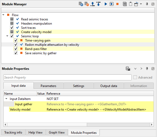
Create a new workflow 0110_Multiple_attenuation_(iteration_1):
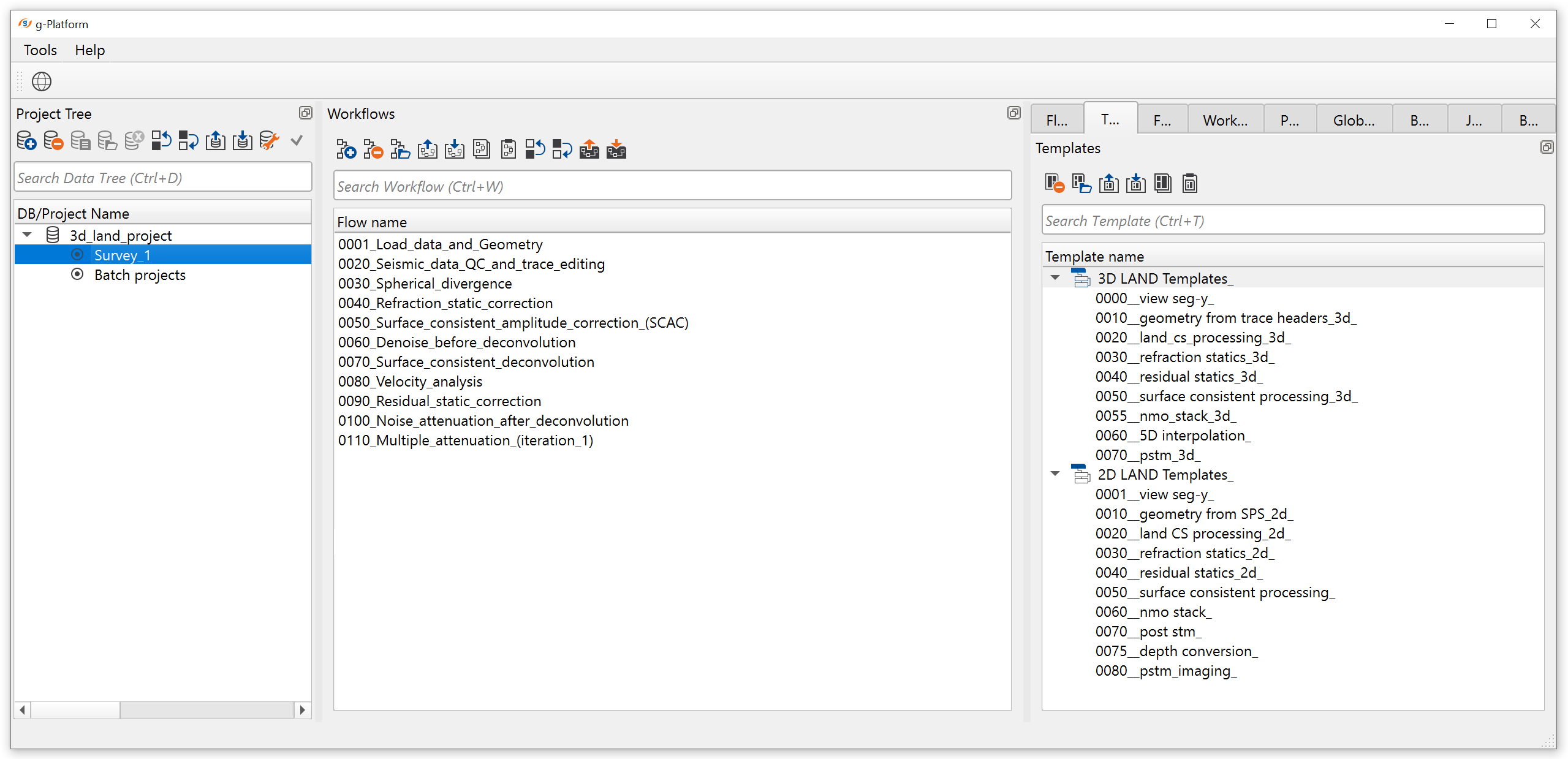
Add all necessary modules to the workflow:
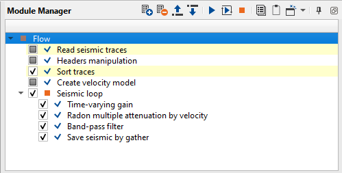
1. Read seismic traces
2. Header manipulation
3. Sort traces
4. Create velocity model
5. Seismic loop
6. Time-varying gain
7. Radon multiple attenuation by velocity
8. Band-pass filter
9. Save seismic by gather
1) Read seismic traces. Load date set from the previous step on multiple attenuation 0100_Denoise_after_decon_02.
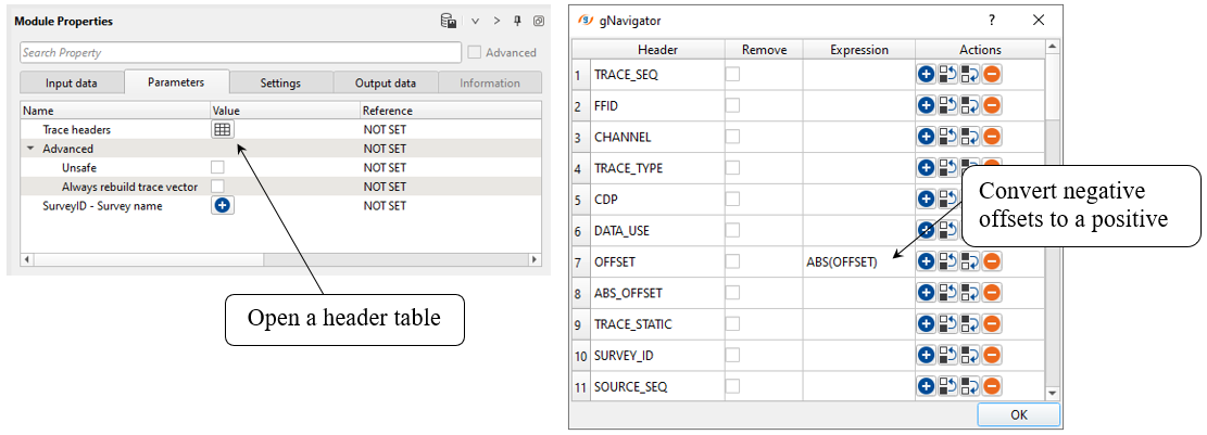
2) Headers manipulation. We can modify trace headers: make offsets only positive (+values). Headers Manipulation module can be useful in doing all sorts of mathematical operations by means of mathematical expressions for changing/manipulating trace headers.
We can use any of the following mathematical operations to create our own equation/expression.
g-Platform uses following mathematical expressions in designing your equation.
• Mathematical operators (+, -, *, /, %, ^)
• Functions (min, max, avg, sum, abs, ceil, floor, round, roundn, exp, log, log10, logn, root, sqrt, clamp, inrange)
• Trigonometry (sin, cos, tan, acos, asin, atan, atan2, cosh, cot, csc, sec, sinh, tanh, d2r, r2d, d2g, g2d, hyp)
• Equalities, Inequalities (=, ==, <>, !=, <, <=, >, >=)
• Assignment (:=, +=, -=, *=, /=)
• Boolean logic (and, nand, nor, not, or, xor, xnor, mand, mor)
• Control Structures (if-then-else, ternary conditional, switch case)
• Loop Structures (while loop, for loop, repeat until loop, break, continue)
Modify OFFSET header -> covert negative values to positive:
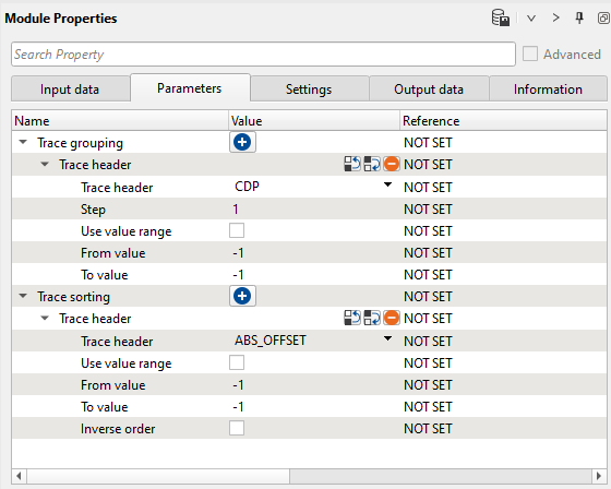
2) Sort traces. Sorting by CDP - ABS_OFFSET (or INLINE, CROSSLINE, OFFSET):
Execute those modules.
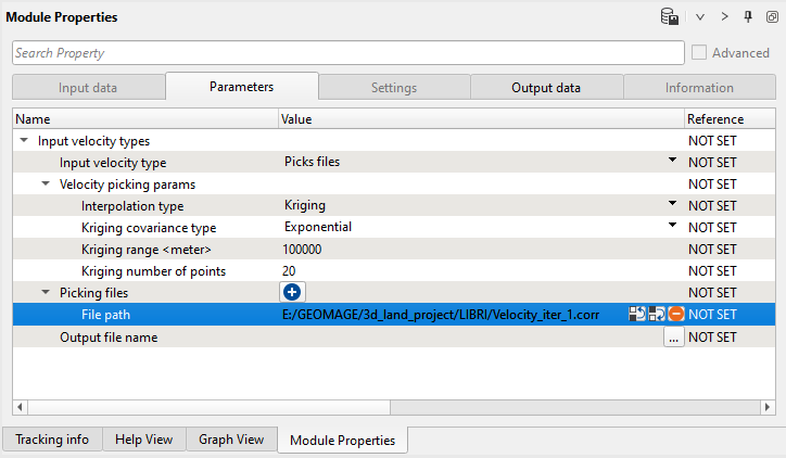
2) Create velocity model. Load stacking velocity (library) from file:
4) Sort traces. sorting by CDP - OFFSET:
Execute those modules.
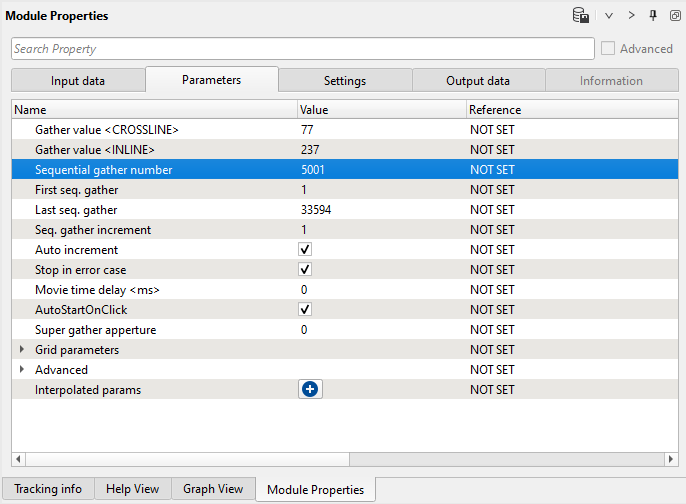
5) Seismic loop. Put two modules inside: Radon multiple attenuation by velocity and Save seismic by gather. Choose some full-fold CMP gather for testing via seismic loop map or set the number manually:
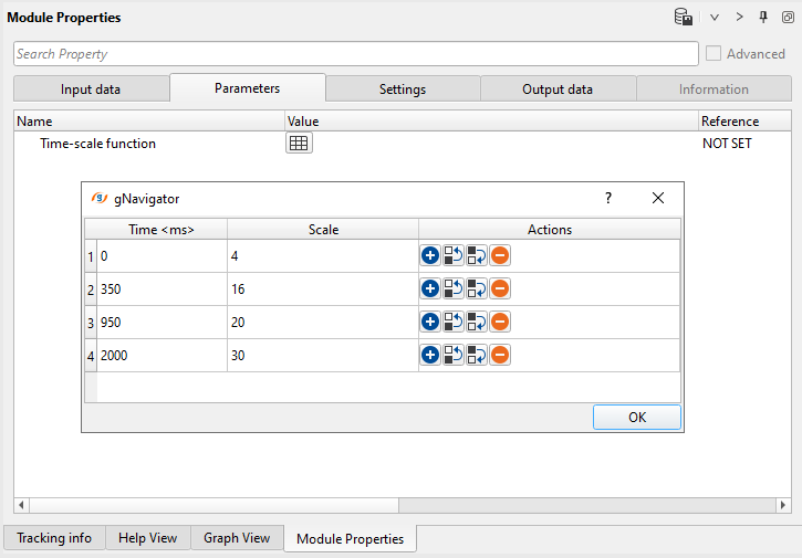
6) Time-varying gain. Usually it is necessary to apply additional time-amplitude compensation to increase amplitudes in the deeper parts of traces. Test different Scale values in Time-scale function table to find best value for correction. Define parameters and execute one CMP gather:
Parameters:
Check results:
7) Radon multiple attenuation by velocity.
This module transforms seismic traces into Tau/P (intercept time and slowness dt/dx = p) domain where we can easily separate multiples and primaries. Such separation allows to attenuate energy of multiple waves before reverse transformation into time domain (T-X). Basic idea is separation primaries and multiples by their velocity (moveout) using velocity percent of primary events. Input traces are decomposed so hyperbolic events map to elliptical curves in Tau-P domain.
Input seismic gather must be sorted by Common Middle Point (CMP) – Offsets. A primaries flatten by applying Normal Move Out correction by input velocity model inside a module before Radon transform. In this case the primary energy will be near P=0, which produces difference in moveout makes it possible to flatten the primary reflections while leaving the multiples under-corrected with a moveout approximately parabolic.
Slowness = 1 / Velocity
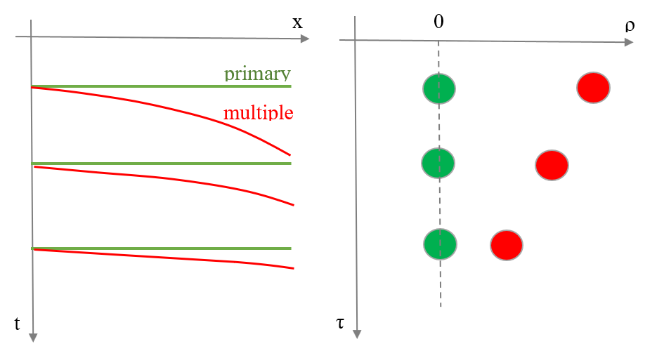
Model of CMP gather: 1) Time domain (T-X): Primaries+Multiples;
2) Tap-P domain: Primaries+Multiples:
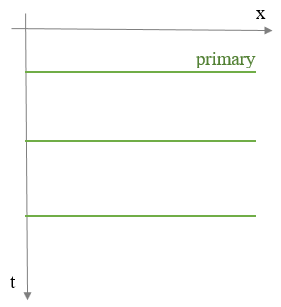
3) Time domain (T-X): Primaries.
The module performs a model of primary and multiple events. This computation is based on data decomposition into user-defined percent of primary velocity and calculated by high-resolution algorithm, de-aliased least-squares method in the frequency space domain for every frequency of the pass-band which is defined by frequency min (Hz) and frequency max (Hz) parameters. Events corresponding to parabolas with a bigger curvature are considered as multiples. Events corresponding to parabolas smaller than this constrain are primary events. The area limits between primaries and multiples is user defined parametrization.
The input data is not NMO-corrected, therefore we should provide velocity model as input data. The module applies velocity before attenuation and reverses NMO corrections on output.
Input data:
Parameters:
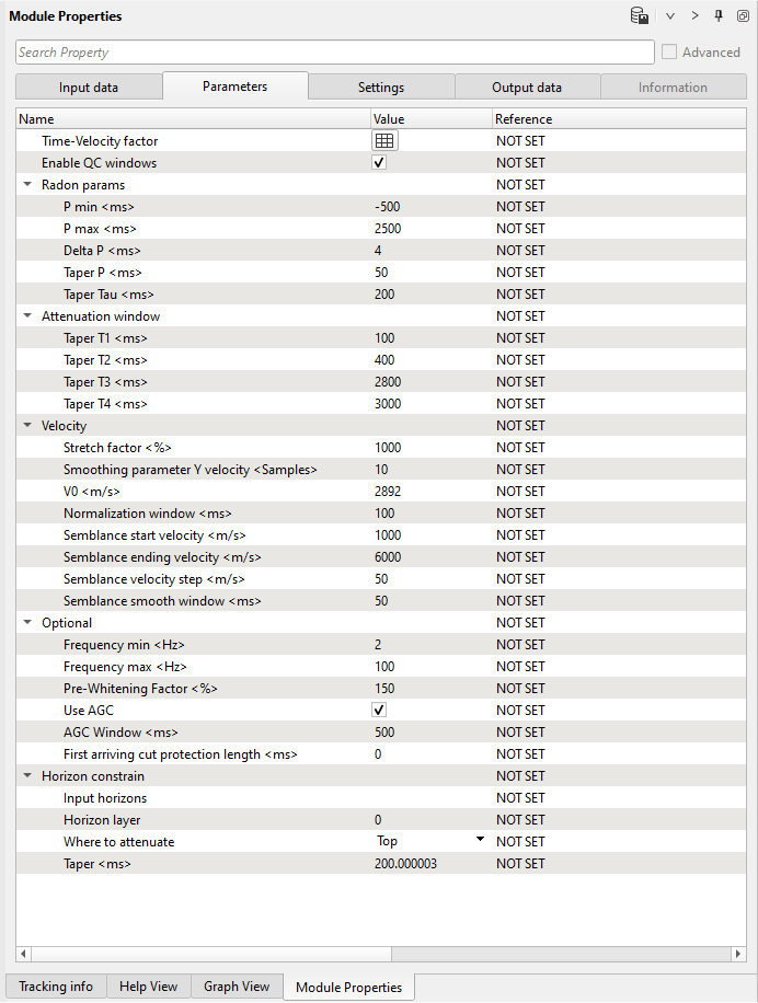
Time-velocity factor (table):
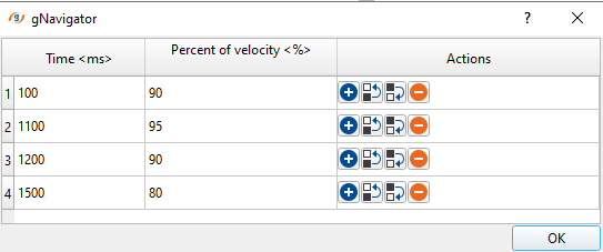
Time-velocity factor
A table with time and percent of velocity columns. Percent means at what velocity we would like to make a limitation for rejection left side of the Radon spectrum.
Enable QC windows
| Switch on/off quality control windows (vista windows). |
Radon params:
Minimum p-value for transform data from t-x into tau-p domain.
Middle p-value for transform data from t-x into tau-p domain.
This parameter is start for modeling multiple waves.
Maximum p-value for transform data from t-x into tau-p domain.
(Choose this parameter with care because run time for this process increases with the square of the number of P-values).
Amount of modeling waves.
Should be approximately equal signal response time interval.
Taper zone between P min/mid/max-values.
Taper zone between start time - filtered - end time.
Taper T1 <ms> - start time for attenuation.
Taper T2 <ms> - end taper zone between T1 and T2.
Taper T3 <ms> - start time zone between T2 and T3.
Taper T4 <ms> - end time for attenuation.
Group of parameters for velocity spectrum building.
Stretch factor <%>
Cutting far offset/near surface stretches.
Smoothing parameter Y velocity <Samples>
Smooth velocity.
V0 <m/s>
Velocity of weathering zone.
Normalization window <ms>
Averaging sample value of velocity spectrum.
Semblance start velocity <m/s>
Start velocity for velocity semblance calculation.
Semblance ending velocity <m/s>
End velocity for velocity semblance calculation.
Semblance velocity step <m/s>
Step for velocity semblance calculation.
Semblance smooth window <ms>
Smooth for velocity semblance calculation.
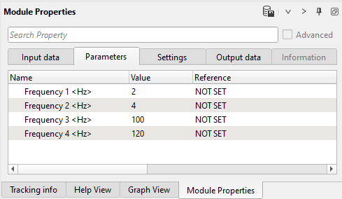
Minimum frequency for filtering
Maximum frequency for filtering
Pre-whitening factor for stabilizing tau-p to t-x transformation.
Apply automatic gain control pre radon filtering and remove after radon filtering.
Window for automatic gain control.
First arriving cut protection length <ms>
Option for using horizons as bounds for spectrum calculation:
Input data item with horizons.
Number of horizon
Mute zone: top or bottom.
Taper zone.
Execute the module and open the following vista windows: NMO Gathers, Velocity Analysis, other windows it is up to you.
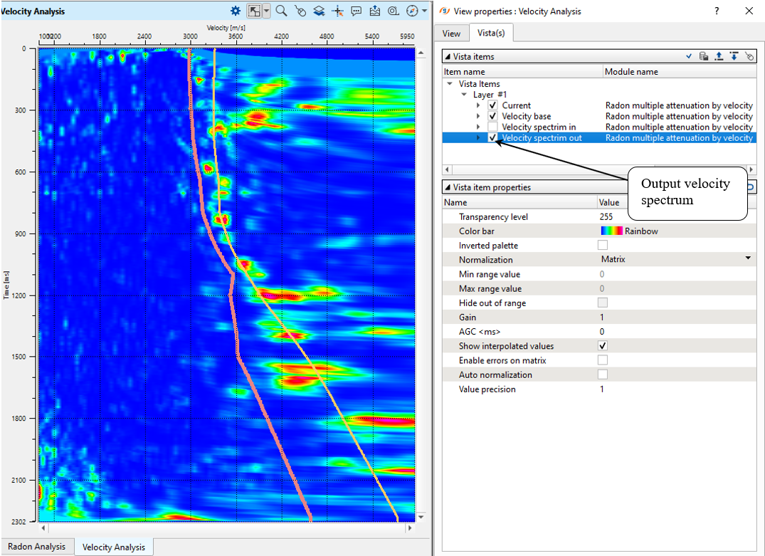
Check input velocity spectrum and change percentage of the input velocity for multiple attenuation:
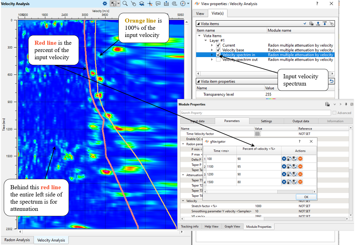
Check an output spectrum after attenuation:
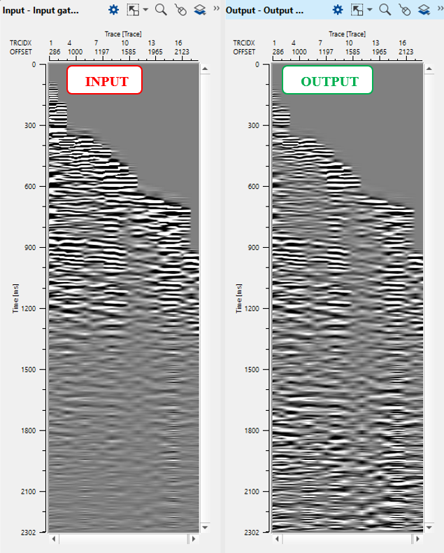
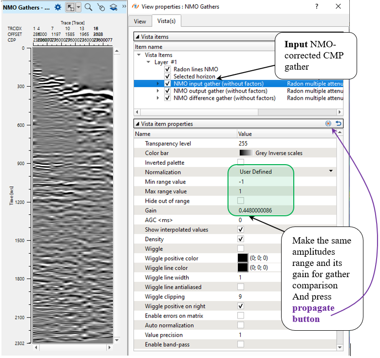
Check the INPUT gather with NMO corrections:
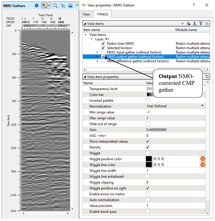
Check the OUTPUT:
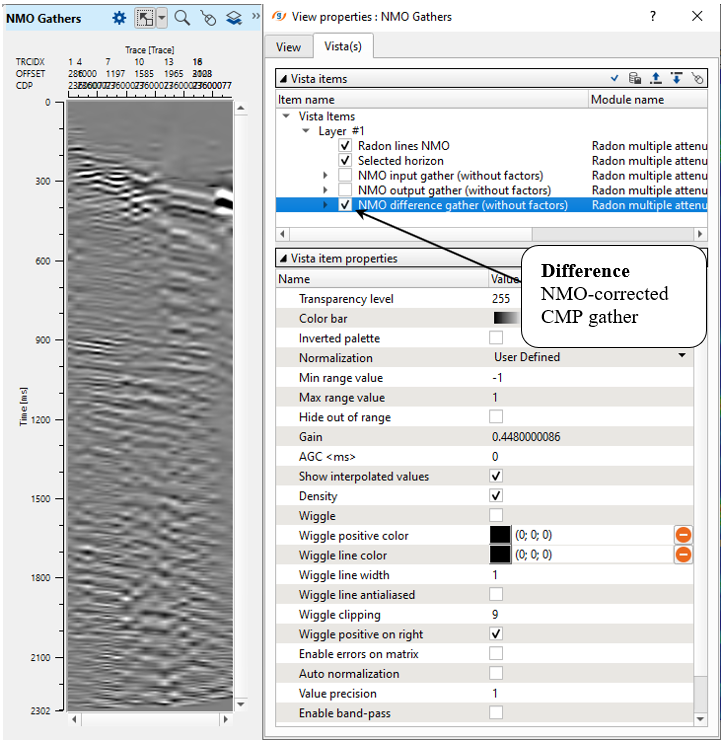
Check the DIFFERENCE:
8) Band-pass filter. Limit the range of an output frequencies, because radon transform may generate low frequency artifacts.
Parameters:
9) Save seismic by gather. Define an output file 0110_Demultiple1 name and execute calculations for the entire data set.
 If you have any questions, please send an e-mail to: support@geomage.com
![]() Frequency Dependent noise attenuation (FDNA) - Geomage g-Platform - YouTube
Frequency Dependent noise attenuation (FDNA) - Geomage g-Platform - YouTube