 | NOISE ATTENUATION AFTER DECONVOLUTION |
| | NOISE ATTENUATION AFTER DECONVOLUTION |
|
<< Click to Display Table of Contents >> Navigation: Tutorials > Seismic Processing 3D LAND >
|
The second iteration of noise attenuation after deconvolution is one of the main part of signal processing sequence before migration step. Here we should apply more intensive parameters and algorithms for removing noise part from seismic data. We need to calculate and apply three of four interations of SCAC, because of the changes in amplitude distribution during the noise attenuation process. Therefore, we will repeat de-noise from the first iteration, but with more harsh noise attenuation parameters and add other algorithms as well.
----------------------------------------------------------------------------------------------------------------------------------------------------
![]() There are many different modules for noise attenuation such a LNA, FK filter, Adaptive ground roll attenuation and others, so you can try to use them and make some extra tests in this step.
There are many different modules for noise attenuation such a LNA, FK filter, Adaptive ground roll attenuation and others, so you can try to use them and make some extra tests in this step.
-----------------------------------------------------------------------------------------------------------------------------------------------------
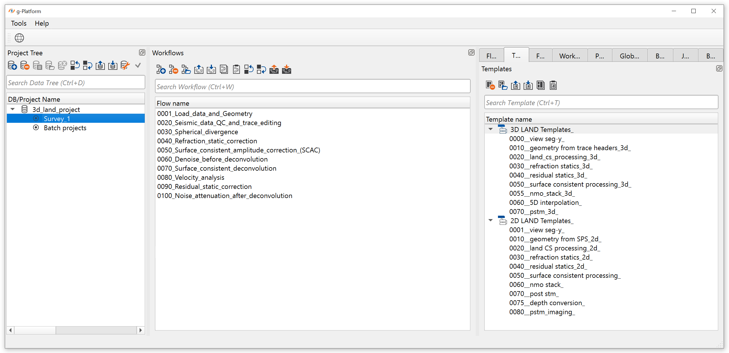
Create a new workflow 0100_Noise_attenuation_after_deconvolution and add all the following modules:
The first part of the job:
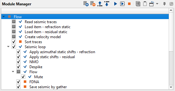
1. Read seismic traces
2. Load item - refraction static
3. Load item - residual static
4. Create velocity model
5. Sort traces
6. Seismic loop
7. Apply azimuthal static shifts - refraction
8. Apply static shifts - residual
9. NMO
10. Despike
11. Mute
12. FDNA
13. Save seismic by gather
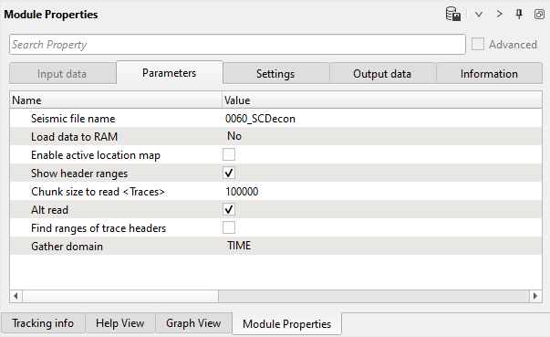
1) Read seismic traces. Load seismic data set 0060_SCDecon.
Parameters:
2) Load item - refraction static. Load refraction static library from data base into current workflow.
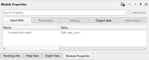
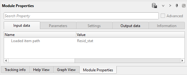
3) Load item - residual static. Load residual static library from data base into current workflow.
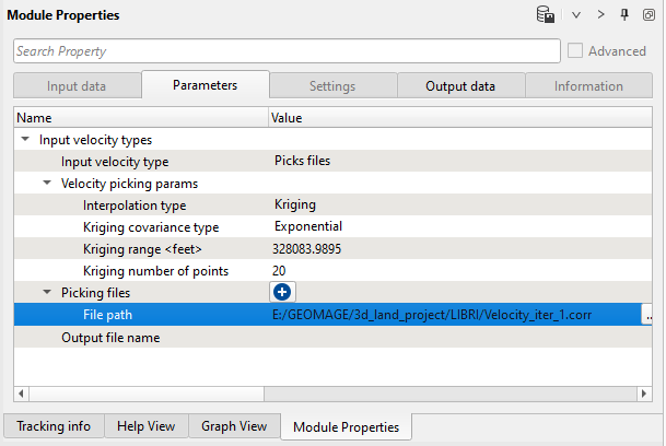
4) Create velocity model. Load velocity library.
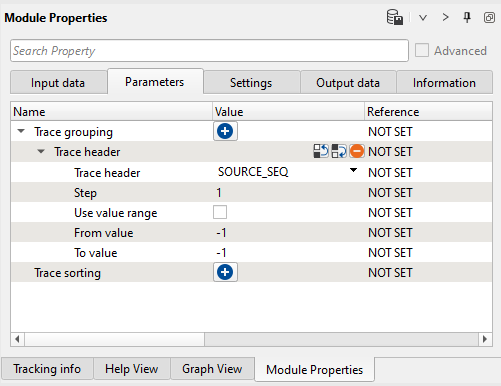
5) Sort traces - by SOURCE. Here we need to sort seismic traces for Seismic loop, not for SCAC (no sort is required for it). Therefore, add Sort traces module and set SOURCE_SEQ, SOURCE_LINE in Trace Grouping and RECEIVER_LINE as Trace sorting header (or just one header for sorting SOURCE_SEQ) for sorting as it is shown below:
Parameters:
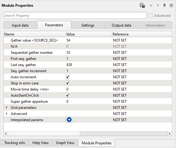
6) Seismic loop. Connect trace headers vector (Input sorted headers) from the Sort traces module output and seismic (Input SEG-Y data handle) from Read seismic traces. Select some source point for testing, let's take Sequential gather number = 555 (or different, it is up to you) as shown in the parameters:
Parameters:
7) Apply azimuthal statics shifts - refraction. This module is used to apply azimuthal refraction statics calculated by Refraction FB picking - Azimuthal solver guide/phase/aperture module. We should make appropriate reference to the statics correction item in Apply azimuthal statics shifts module by connecting Load item (refraction static) and select GAzimuthalRefractionStaticsCorrectionItem as shown below.
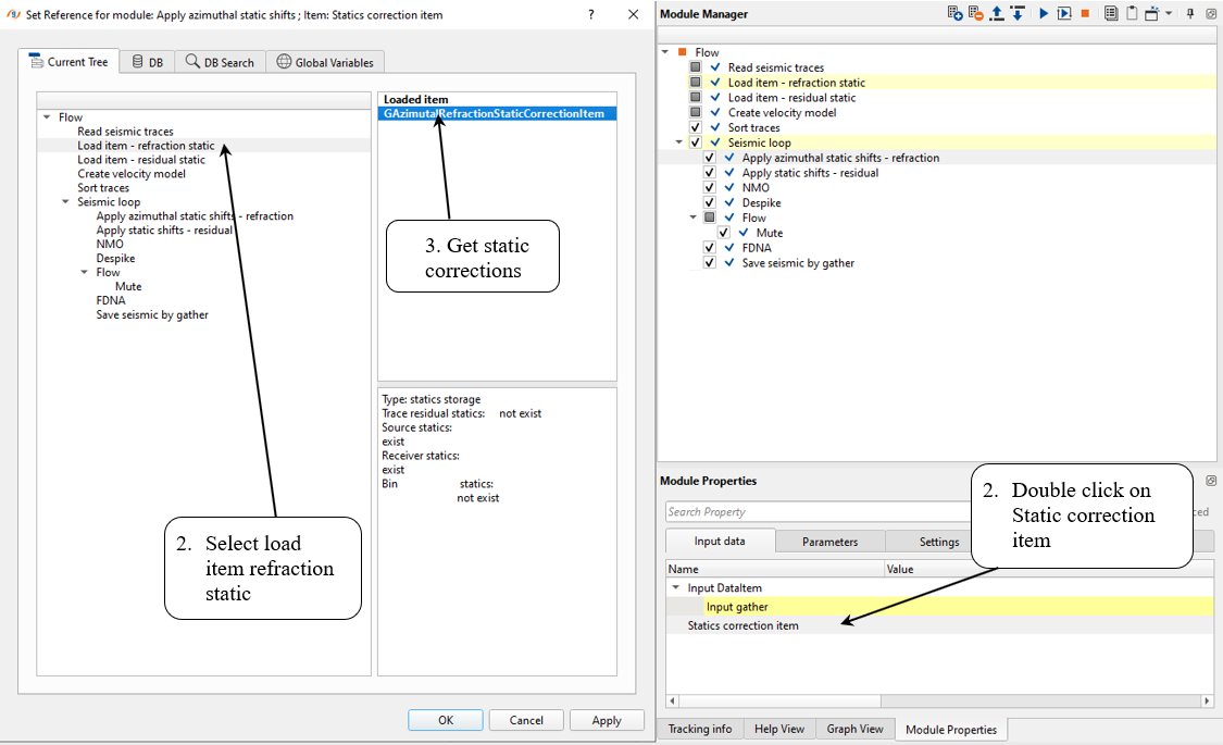
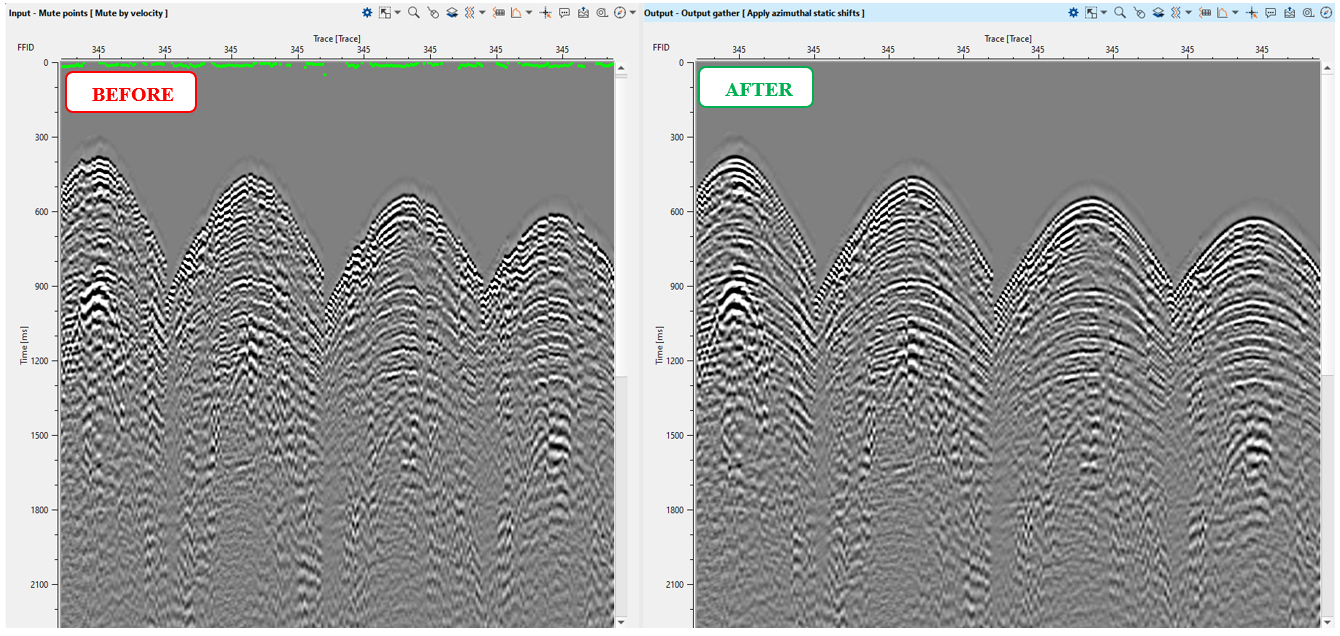
This will apply the refraction statics to the input data. We can see the gather before and after refraction statics by comparing the Vista items.
On the top of the Input gather, we can observe the refraction statics plot. If the user wants to turn them off, go to View properties and uncheck Statics curve option.
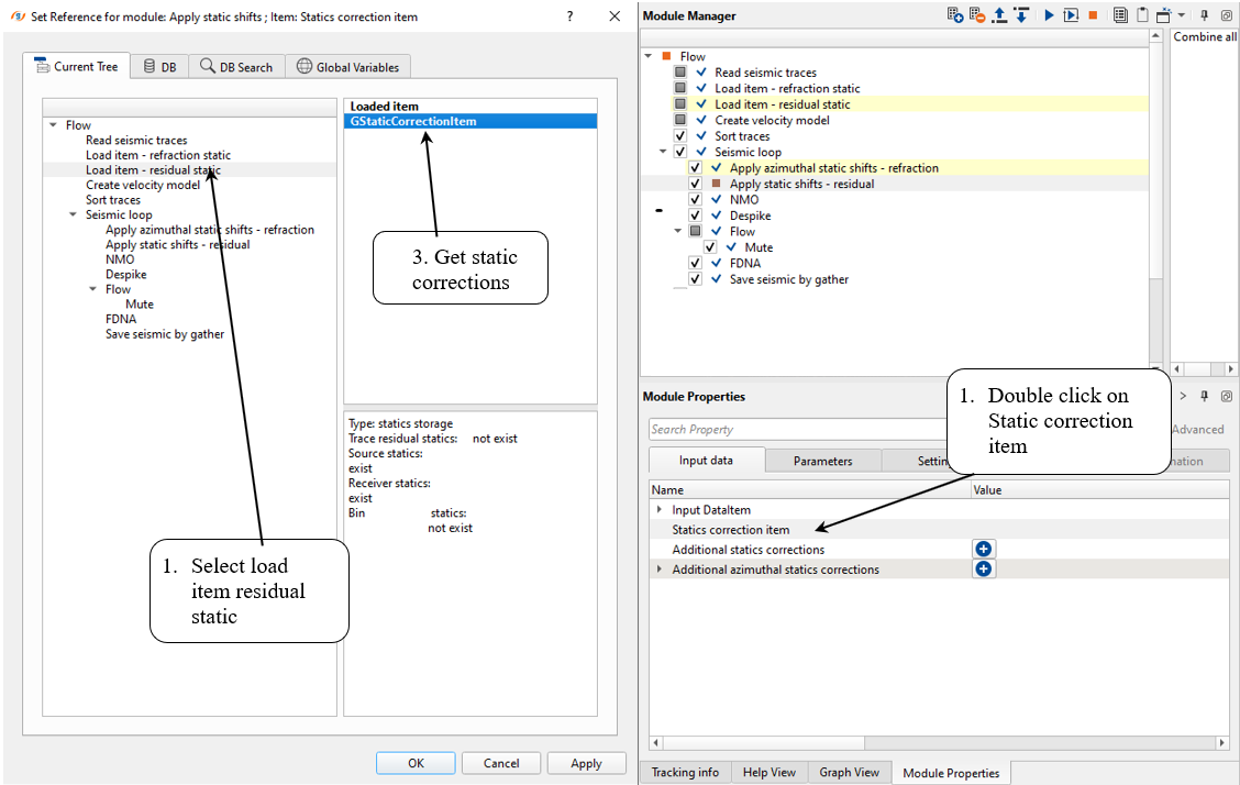
8) Apply statics shifts - residual. This module is used to apply residual statics (or previous module, which allow to apply both type of statics, see input data paramters). Get statics correction from module:
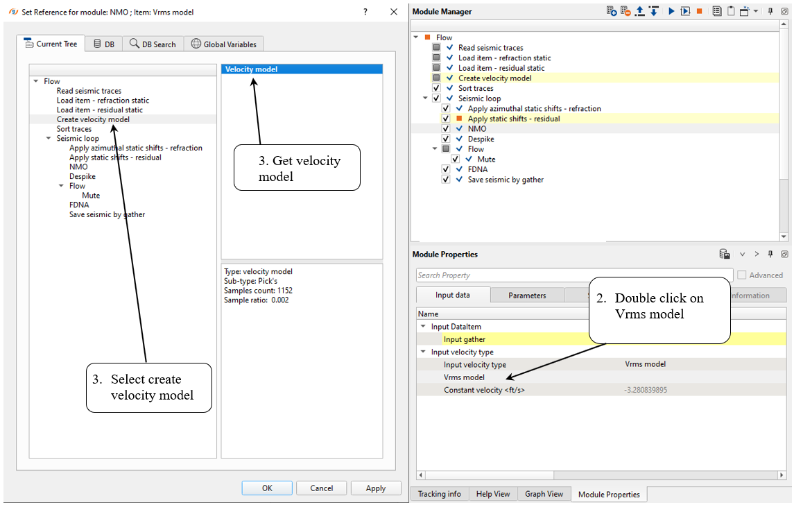
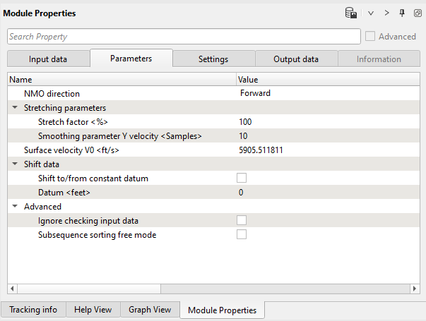
9) NMO. This module is used to apply normal move out corrections:
--------------------------------------------------------------------------------------------------------------------------------------------------------------------------
![]() IMPORTANT! We must apply NMO corrections on gather which was sorted by CDP. But in this case of denoise task by source gathers we can apply NMO and remove it after denoise (2nd part of the workflow).
IMPORTANT! We must apply NMO corrections on gather which was sorted by CDP. But in this case of denoise task by source gathers we can apply NMO and remove it after denoise (2nd part of the workflow).
--------------------------------------------------------------------------------------------------------------------------------------------------------------------------
10) Despike module allows the user to remove amplitude spikes (high amplitude values that are many times larger than adjacent values) from seismic traces. Spikes are not normal seismic signal, they are usually created by the recording equipment and hence should be removed. Spike identification and removal is based on the average (depending on the chosen parameter) amplitude calculated in a time window and spatial window for each sample of the seismic trace in accordance with chosen threshold coefficient.
Parameters:
Execute Despike and check the result:
11) Mute. This module is useful in creating the model gather for next module FDNA which requires two input dataset. One is input data and the second one is model gather. To create the Model gather, we are using Mute. In this instance, we would like to attenuate the remnant ground roll noise using FDNA module. For that reason, we are designing an inner mute by using Mute by velocity module. The output from Mute by velocity will act as a Model gather to FDNA.
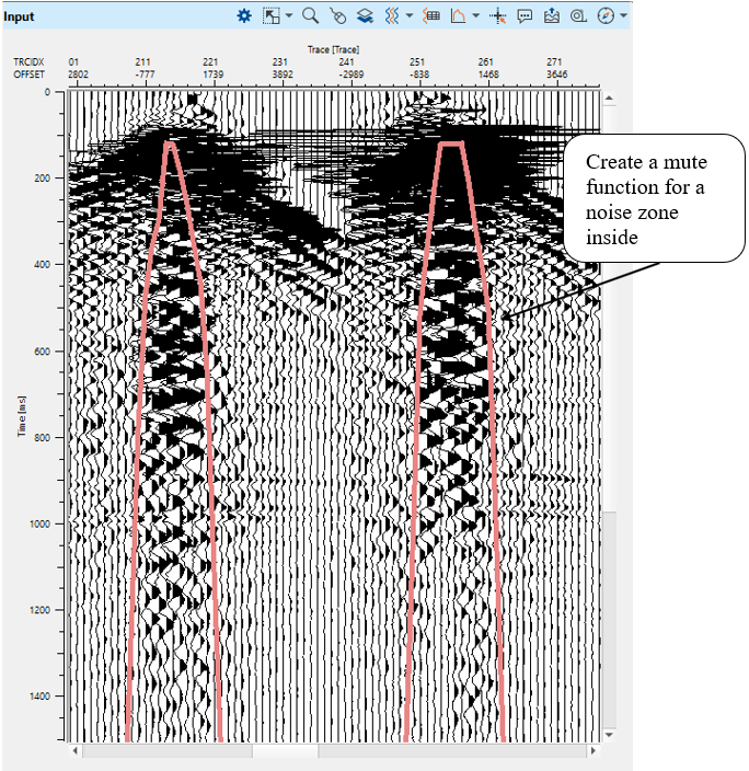
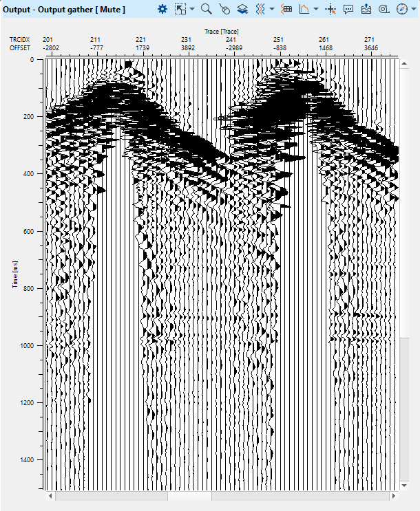
Execute the Mute module to see the model for FDNA:
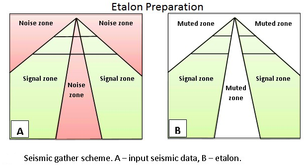
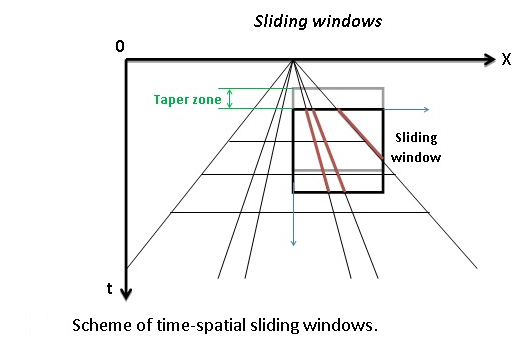
12) FDNA (Frequency Dependent Noise Attenuation) module uses frequency-dependent and time-variant algorithm where an amplitude threshold values are defined in a trace neighbor area (T-X) for detecting and noise attenuation according to different frequencies and different time windows. The attenuation process consists of two steps – First prepare the etalon (model) and noise attenuation data sets. The etalon should contain only the signal zones, with the noise zone muted (see Pic.1). The module estimates the median value of the amplitude spectrum in the sliding windows of the etalon data set, and for each window computes an operator using the threshold value. The procedure attenuates amplitudes whose values exceed the specified threshold.
Input data – Two seismic data sets are input to the FDNA module.
The Input gather are 2D/3D seismic gathers in source or receiver sort order. It is better if they are NMO corrected and static corrections have been applied, but for this step we can apply denoise sequence in a soft mode without NMO correction.
The Model gather is the etalon of 2D/3D seismic gathers in source or receiver sort order. The same idea: it is better if they are NMO corrected and static corrections have been applied, but for this step we can apply denoise sequence in a soft mode without NMO correction.
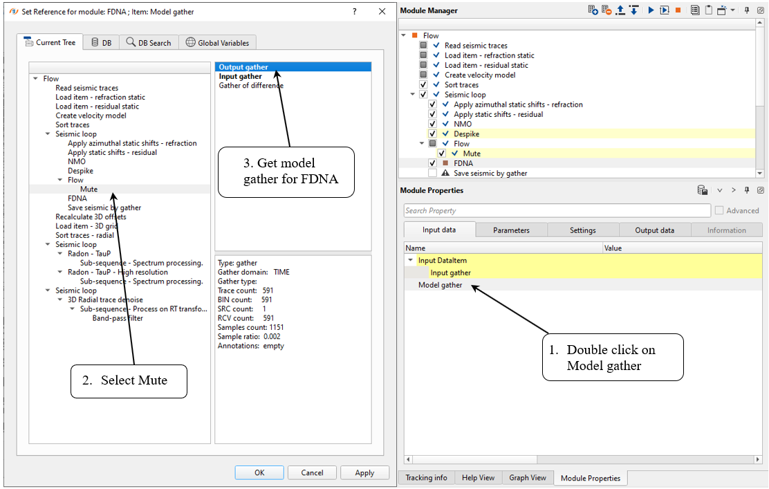
Seismic loop makes automatic connections between all modules in a sequence under that seismic loop and the user cannot disconnect them. In this case, we need to use an additional Flow module inside of the Seismic loop for etalon preparation. Put the mute modules into a Flow inserted into the Seismic loop and then connect the output muted data to the Model gather field of the Input data tab of the FDNA module. The Input gather on the Input data tab will be automatically connected to the previous module in the Seismic loop processing flow.
Firstly, we need to create an etalon for FDNA by using Mute by velocity module:
Next, we need to connect input Model gather (etalon) with output from the Mute module and Input gather from Despike (which will automatically connect within the Seismic Loop module)
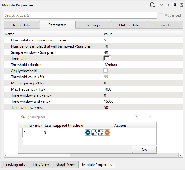
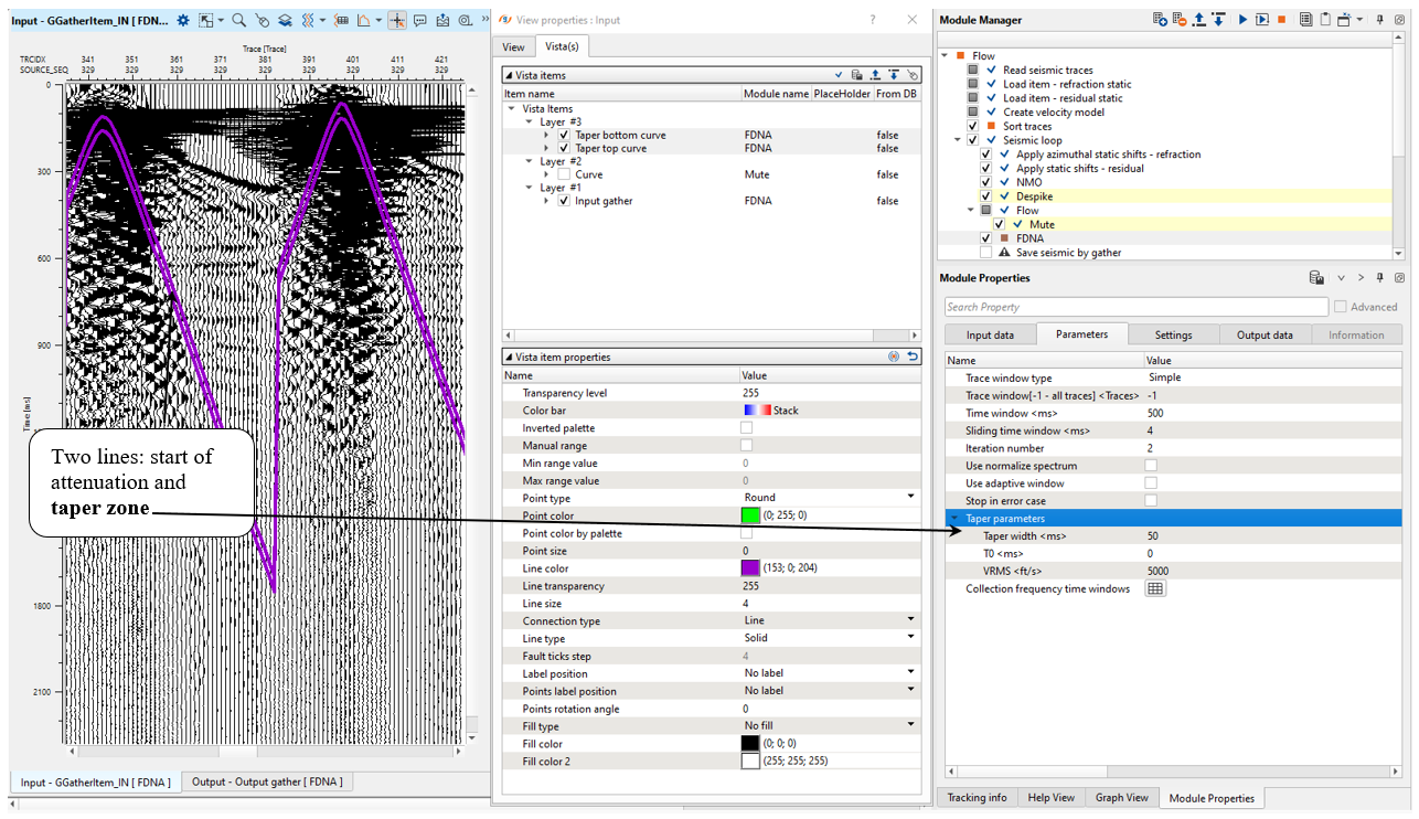
Parameters:
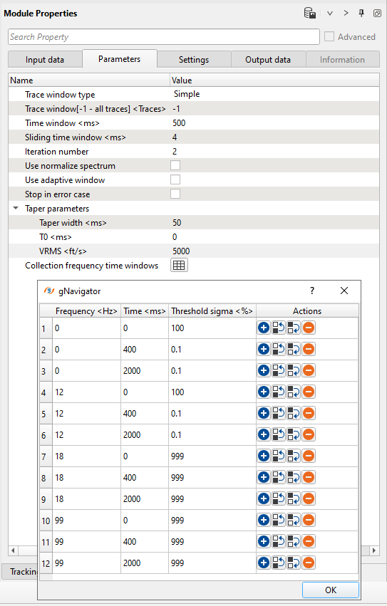
Parameter definition:
Number of traces to use for the sliding window. This window is used for local attenuation.
Default: -1 (all traces)
Range: from 1 to max traces in the input gather
Time in milliseconds for sliding window. This window used for local attenuation. The taper zone between sliding windows is ¼ of time window length default 200ms.
Sliding time window - Amount to advance the sliding time window each shift
Three parameters of basic control noise attenuation:
• Frequency– frequency for attenuation;
• Time– time value for threshold;
• Threshold– the limiting parameter for calculating threshold values to attenuate excessive amplitudes.
Carefully prepare the etalon (model) data, try to mute the high amplitude zones and include the signal zones.
Control the noise attenuation by using the threshold parameters and the ability to specify the thresholds in a time variant manner and by frequency.
This procedure is more effective in the first steps of the seismic data processing flow when noise zones still have high amplitudes. The input seismic data should not be amplitude normalized.
Also, look at Input gather vista view and check a zone for removing, which is set by module's parameters:
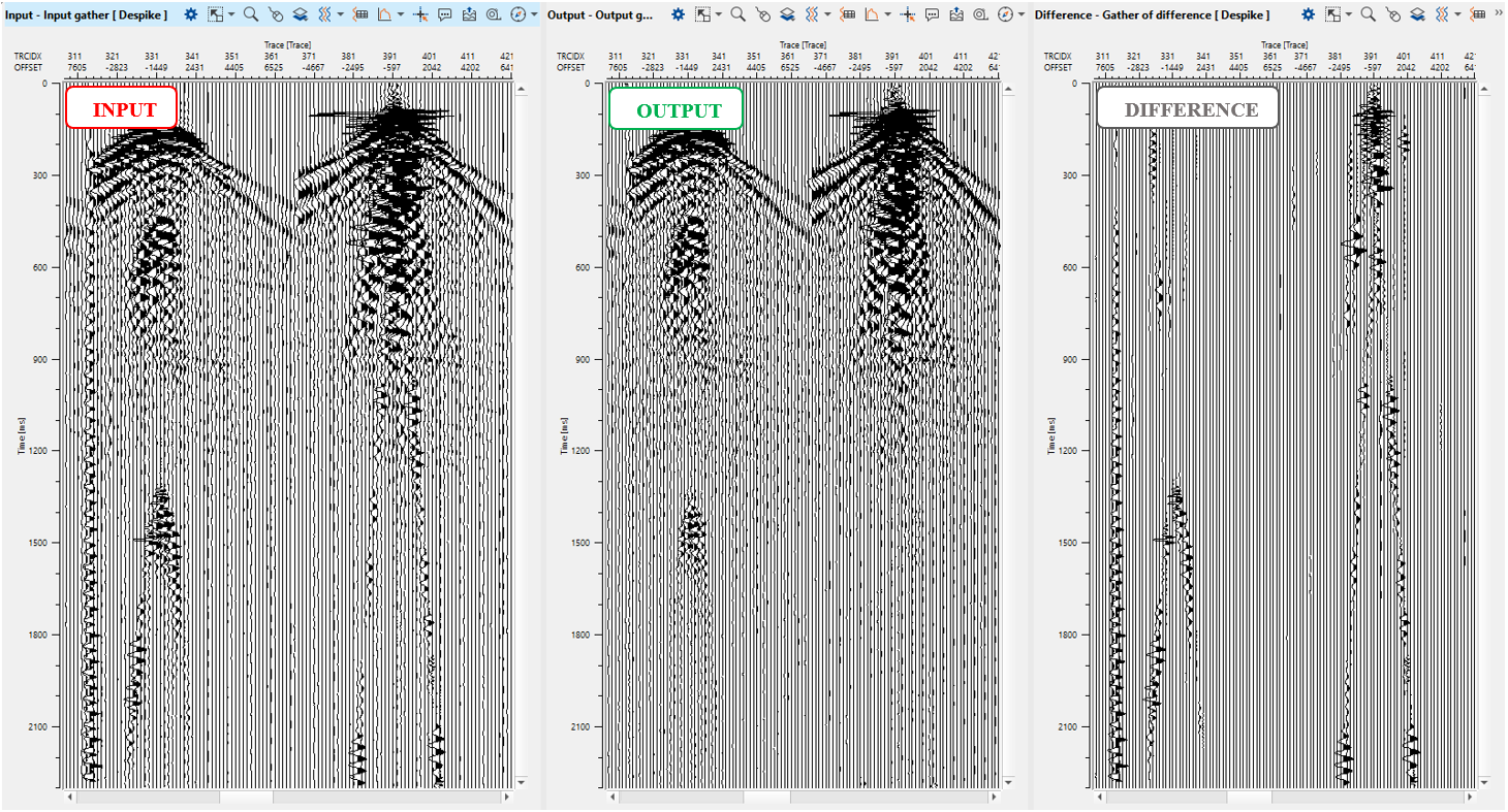
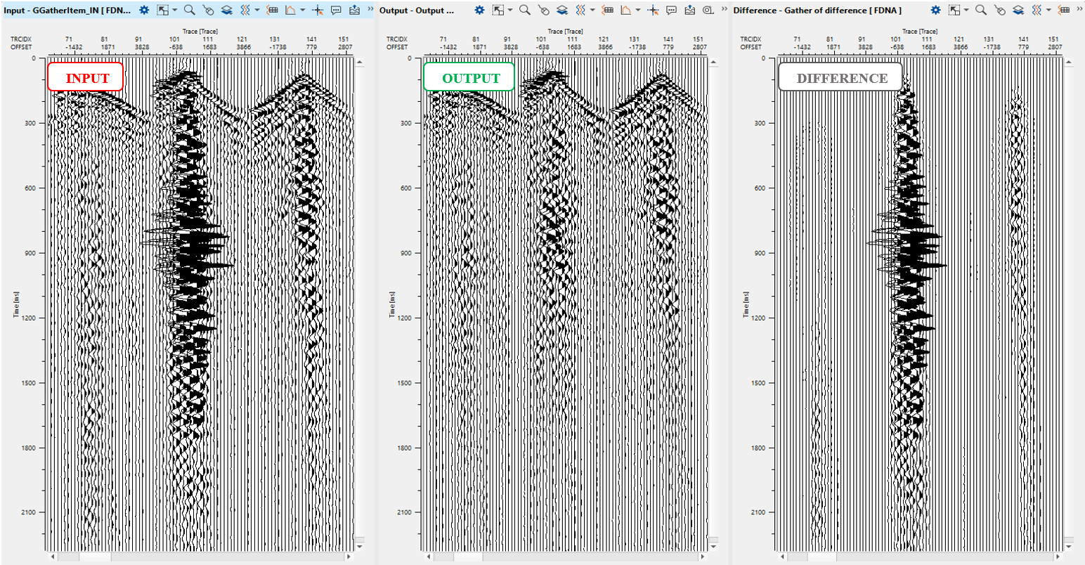
Execute FDNA and check the result:
-----------------------------------------------------------------------------------------------------------------------------------------
![]() Pay attention that in g-Platform system we are able to execute workflows with using many threads and nodes in parallel mode. For example, Distributed Seismic loop module may be used in case of large 3D data set.
Pay attention that in g-Platform system we are able to execute workflows with using many threads and nodes in parallel mode. For example, Distributed Seismic loop module may be used in case of large 3D data set.
------------------------------------------------------------------------------------------------------------------------------------------
13) Save seismic by gather. We have to save seismic on disk, because the next part of the flow uses different sorting. Define a name for output data set 0100_Denoise_after_decon_P01 . Execute Seismic loop for the entire data (press ![]() button from upper menu). Don't forget to switch off difference option in modules!
button from upper menu). Don't forget to switch off difference option in modules!
SECOND PART

14. Read seismic traces
15. Load item - 3D grid
16. Recalculate 3D offsets
17. Sort traces
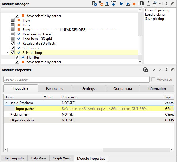
18. Seismic loop
19. FK Filter
20. Save seismic by gather
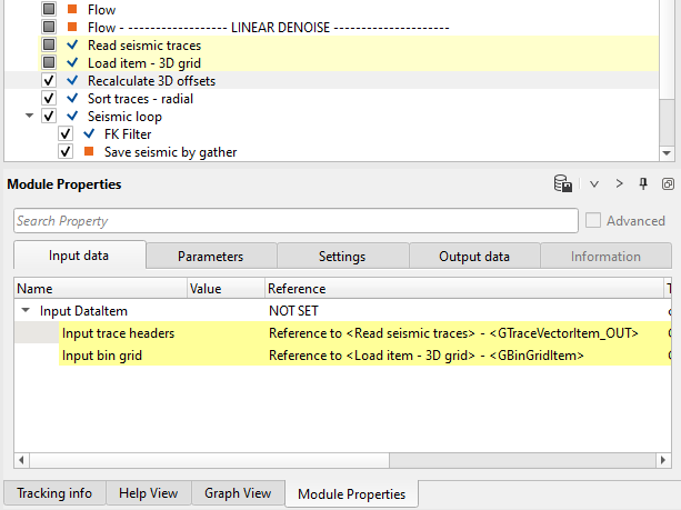
14) Read seismic traces. Load seismic data set 0100_Denoise_after_decon_P01.
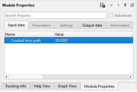
15) Load item - 3D grid. Load 3D grid library from data base into current workflow for recalculate offsets (split it to negative and positive).
Input data:
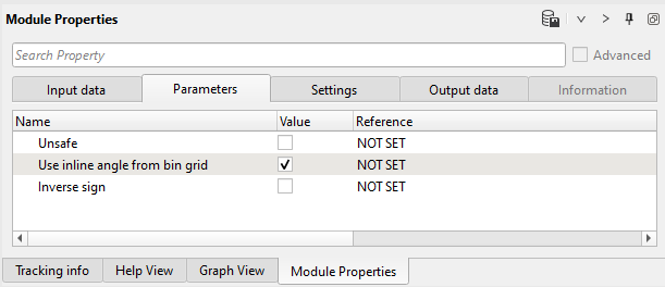
16) Recalculate offsets. We need to recalculate offsets for the next processing in a loop due to the fact that we have 3D data set (some modules requires splitting).
Input data:
Parameters:
We will check offsets by seismic loop.
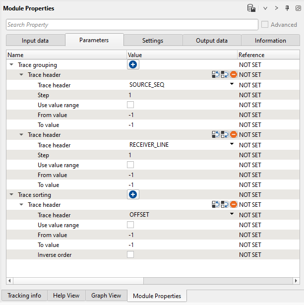
17) Sort traces. Here we need to sort seismic traces for Seismic loop, add Sort traces module and set SOURCE_SEQ, SOURCE_LINE in Trace Grouping and Offsets as Trace sorting header for sorting as it is shown below:
Parameters:
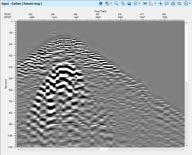
18) Seismic loop. Connect trace headers vector (Input sorted headers) from the Sort traces module output and seismic (Input SEG-Y data handle) from Read seismic traces. Check offsets (negative and positive), open input gather vista view. Add offset trace header on the top of gather and check it:
19) FK Filter. The same module that we already used in previous steps: this module applies an FK filter. FK transforms 2D data to frequency-wave number space. The user can then define a mute zone in that space to apply an FK filter. There are several modules for linear denoise we can use: FK Filter, LNA, Radon Tau-P modules. All this modules can produce similar results, so what to use depends on geophysicist or client preferences. We will use FK FIlter.
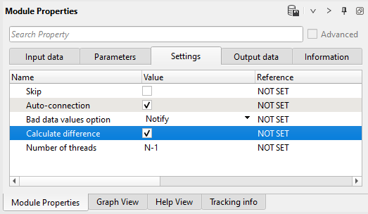
Connect input seismic data item from the first part of the workflow, define parameters, select difference calculation in the Settings tab:
Input data:
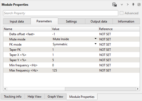
Parameters:
Settings:
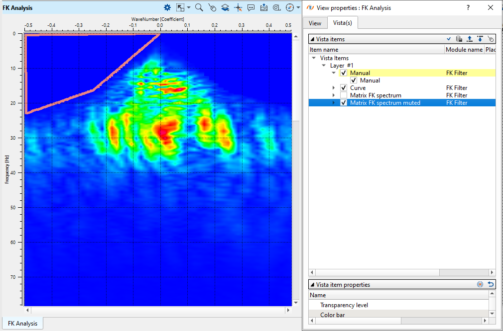
Open FK vista window and draw a mute polygon as shown below:
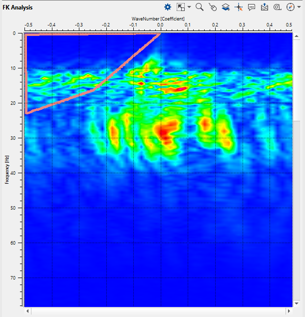
Check muted spectrum, we use symmetric mode (look at the Parameters tab):
Execute the module and check result:
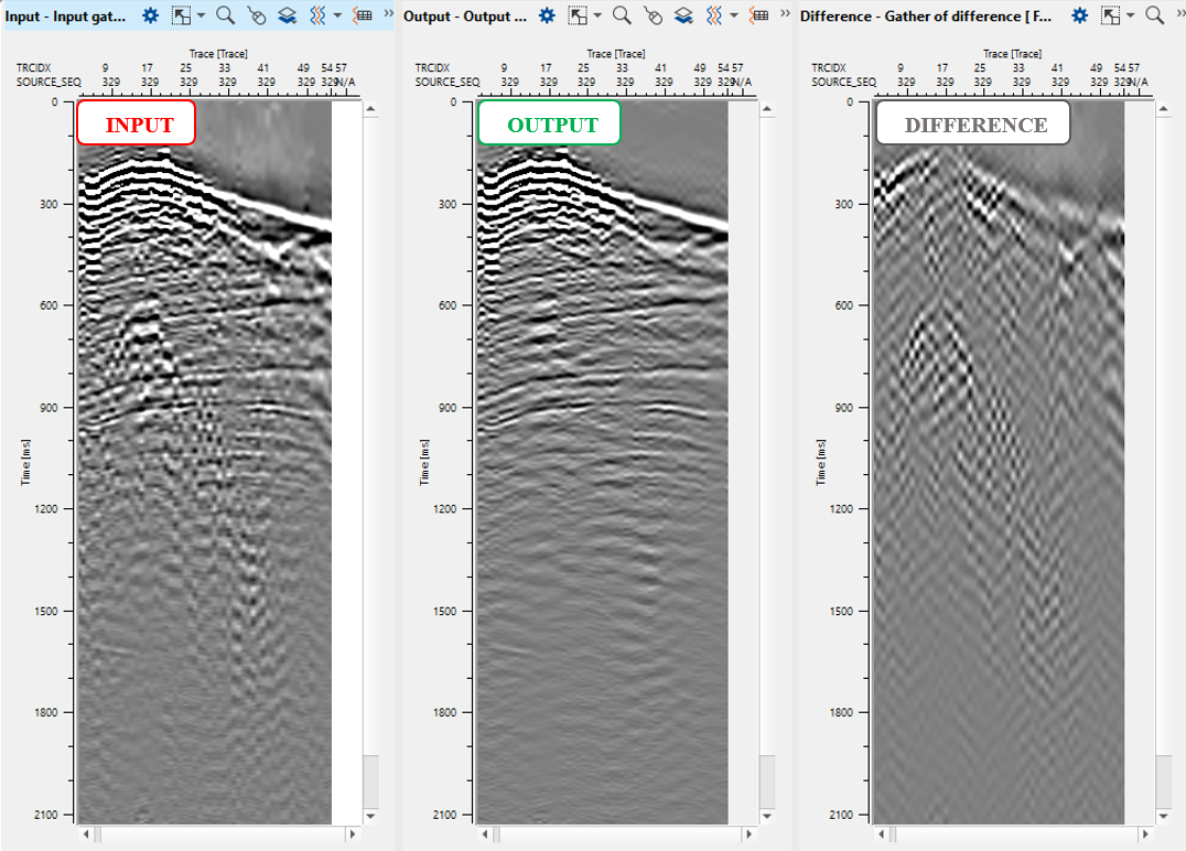
The result quite harsh in terms of de-noising, but for training reasons it is enough, but we can try make parameters softer and re-run the job.
20) NMO - reverse. Remove NMO-correction.
21) Save seismic by gather. We have to save seismic on disk, because the next part of the flow uses different sorting. Define a name for output data set 0100_Denoise_after_decon_P02 . Execute Seismic loop for the entire data (press ![]() button from upper menu). Don't forget to switch off difference option in modules!
button from upper menu). Don't forget to switch off difference option in modules!
STACKS QC
 If you have any questions, please send an e-mail to: support@geomage.com
![]() Frequency Dependent noise attenuation (FDNA) - Geomage g-Platform - YouTube
Frequency Dependent noise attenuation (FDNA) - Geomage g-Platform - YouTube
![]() Linear Noise attenuation (LNA) - Geomage g-Platform - YouTube
Linear Noise attenuation (LNA) - Geomage g-Platform - YouTube
![]() Despike - Geomage g-Platform - YouTube
Despike - Geomage g-Platform - YouTube