 | SURFACE CONSISTENT DECONVOLUTION |
| | SURFACE CONSISTENT DECONVOLUTION |
|
<< Click to Display Table of Contents >> Navigation: Tutorials > Seismic Processing 3D LAND >
|
The surface-consistent minimum-phase deconvolution procedure represents a seismic trace as a composition of a source, receiver, offset, and CMP components. The earth response includes reverberation, attenuation, and ghosting effects that we are going to remove from the signal part of the seismic data. The main goal of deconvolution is to measure these undesirable effects and describes them as filters, create and apply inverse filters. Onshore seismic processing sequence usually all four components normally are used in the decomposition, but usually only the shot and receiver portions are applied. This module is the statistical deconvolution (spike or predictive) where the autocorrelation function is computed from the input seismogram, so you should transform the input seismic data to a min-phase type before applying the SC deconvolution process, for example if source is vibro (zero-phase signal).
A single operator calculated for all traces that have the same surface point location in common. Surface consistent deconvolution assumes that a seismic trace consists of the convolution of a number of components which go together to produce the seismic trace. For example, each shot, each receiver position, each CMP and each trace offset (or channel number) contributes its own spectral modification to the seismic trace.
Surface consistent deconvolution attempts to reverse this process by extracting the original log spectra (for each shot, each receiver) from all of the original input data. This is done by averaging the log spectra for each shot, each receiver, each CMP and each offset (channel) and then using a Gauss-Seidel iterative technique to isolate the individual components.
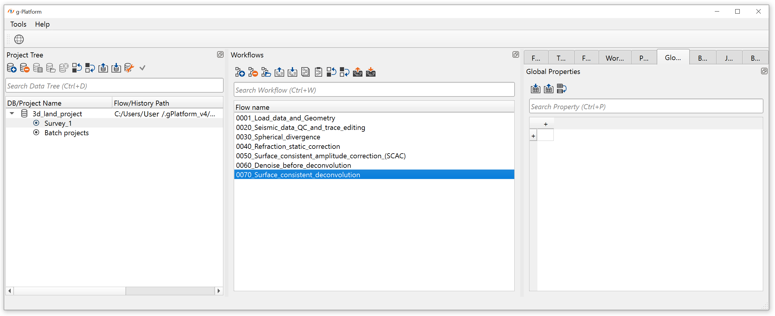
Create a new workflow 0070_Surface_consistent_deconvolution:
The deconvolution step is usually spitted in tree parts:
•Min.phase conversion, if necessary (in case of using spike decon + zero phase/vibro input data)
•Deconvolution (step 1 - calculation): Autocorrelation, spectrum and filter calculation - SC Deconvolution - calculate;
•Deconvolution (step 2 - applying): Filter applying - SC Deconvolution - apply:
Min.phase conversion will be in separated part of the flow, so you can split you job into two parts via Flow modules. Add all modules for min.phase conversion as it is shown below:
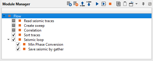
1. Read seismic traces
2. Create sweep
3. Correlation
4. Sort traces
5. Seismic loop
6. Min Phase Conversion
7. Save seismic by gather
MINIMUM PHASE CONVERSION
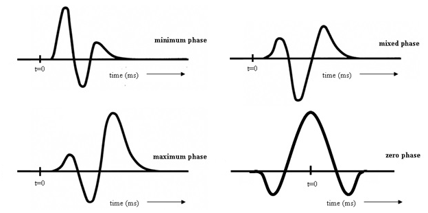
For that task we are able to use different modules like Create sweep, Min Phase Conversion and others. The input seismic data is vibro, so according to the theory the signal is zero-phase and real recorded traces is some kind of mixed phase data. But min.spike deconvolution requires a min-phase data as input. Therefore, we need to transform a seismic data set from zero-phase to min-phase type by using the following steps: create a model sweep wavelet (autocorrelation) which is a representation of the original impulse and perform minimum phase conversion of the input seismic data.
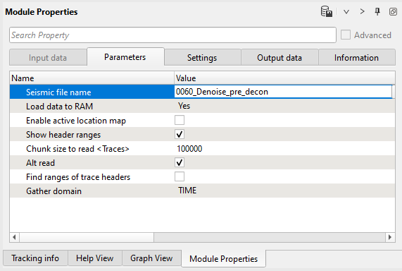
1. Read seismic traces. In this module use load to RAM option, because we are not going to put Min Phase Conversion inside the Seismic loop, so we have to upload traces to RAM. Notice, that we do it only in this flow just to see how we can work with seismic data in g-Navigator. Use seismic data set from the previous step 0060_Denoise_pre_decon.
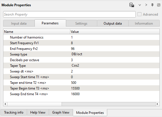
2. Create sweep. Create a model sweep wavelet. Definition for a sweep you can find in the field documentation. Define parameters for the module:
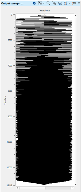
Execute a module Create sweep, open a vista view and check a sweep response:
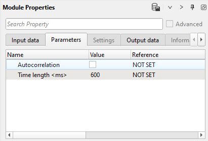
3. Correlation. Add the next module Correlation for creation a auto correlation function of the sweep response. Get sweep wavelet as input for autocorrelation. There are two option for autocorrelation: use option Autocorrelation or use two sweeps as input 1 and input 2, then perform correlation. Define parameters of Correlation module:
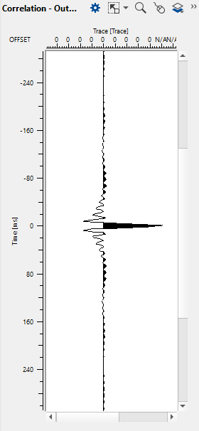
Execute the module and you get auto correlation function of the sweep response:
4. Sort traces - by SOURCE. Here we need to sort seismic traces for Seismic loop. Therefore, add Sort traces module and set SOURCE_LINE, SOURCE_SP, RECEIVER_LINE, RECEIVER_SP (or just SOURCE_SP, because the input seismic data set was sorted by source sequence) for sorting as it is shown below:
Parameters:

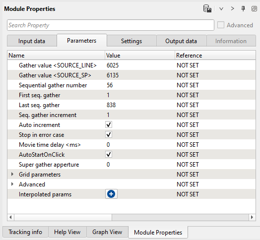
5. Seismic loop. Connect trace headers vector (Input sorted headers) from the Sort traces module output and seismic (Input SEG-Y data handle) from Read seismic traces.
Parameters:
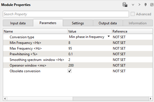
6. Min.phase conversion. The next module is Min Phase Conversion, it performs creation a minimum phase operator from the input model (in our case it is a AFC of sweep) and apply this operator to the input seismic data set.
Connect input data data items:
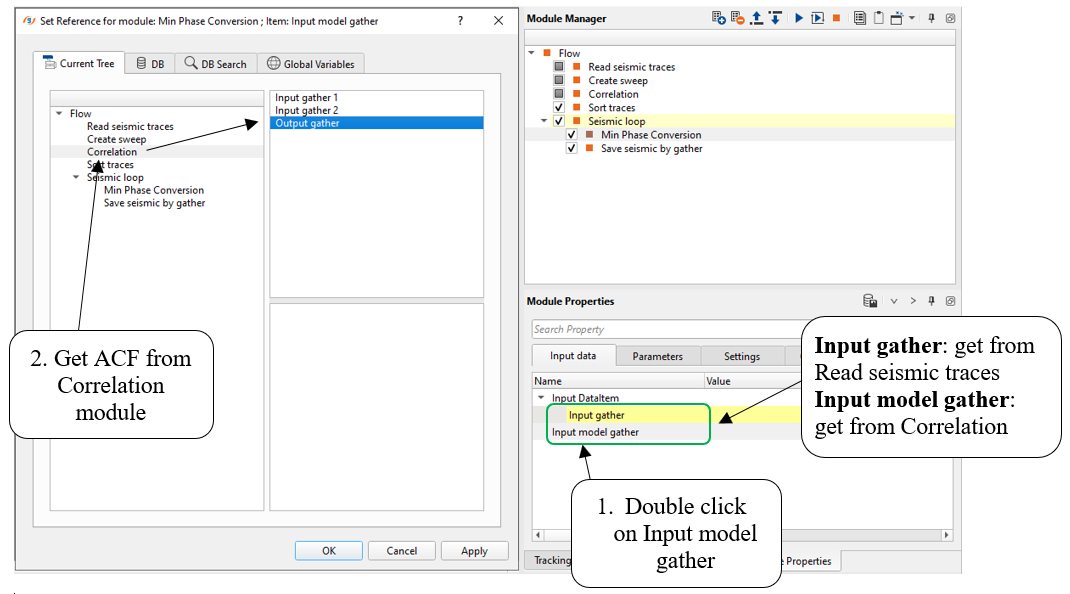
Define its parameters and execute the module:
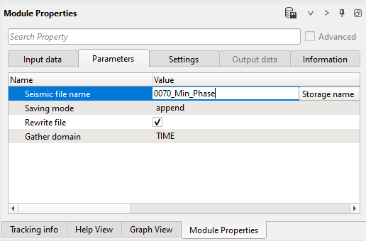
7. Save seismic by gather. Define and output file name 0070_Min_Phase and execute the seismic loop for the entire data set. Input seismic data was converted to a minimum phase type, so we can go the the min phase spike deconvolution process.
DECONVOLUTION [STEP 1 - CALCULATION]
The second part of the workflow is deconvolution that is also splitted two parts: the first step in deconvolution is calculation of Autocorrelation, spectrum and filter calculation. Pay attention that decon module does not have window parameters, therefore we have to apply mute function for input seismic data. The entire workflow look like that:
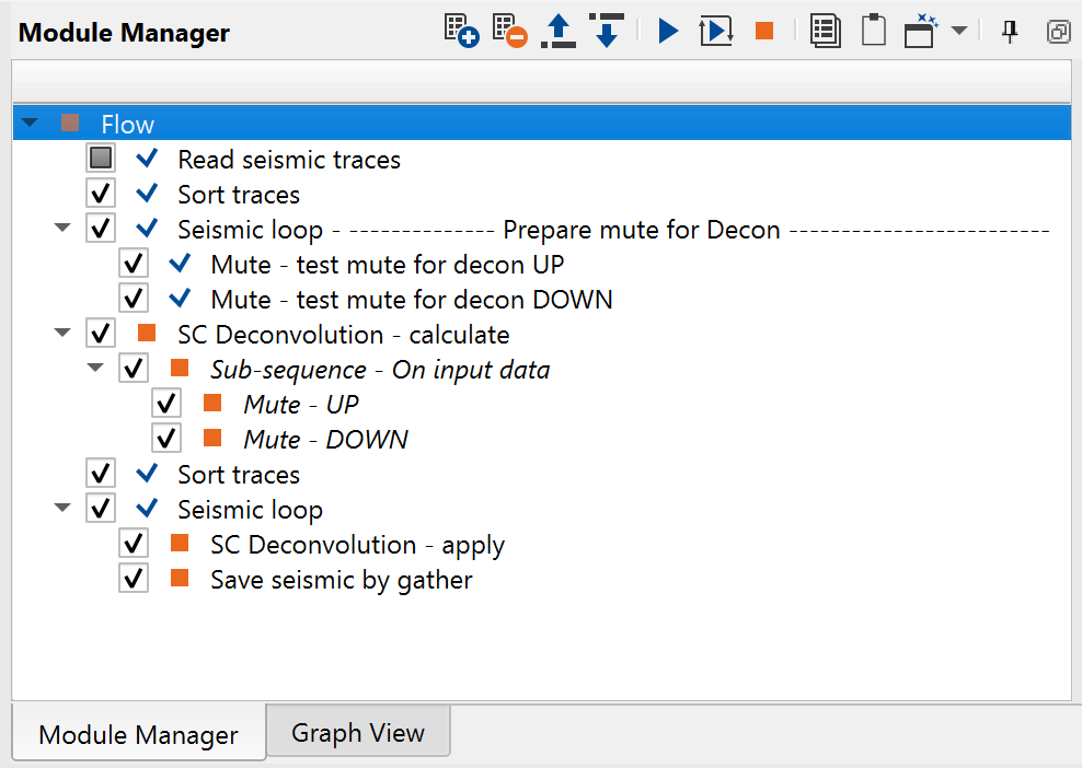
1. Read seismic traces
2. Sort traces
3. Seismic loop
4. Mute - test mute for decon UP
5. Mute - test mute for decon DOWN
6. SC Deconvolution - calculate
7. Sort traces
8. Seismic loop
9. SC Deconvolution - apply
10. Save seismic by gather
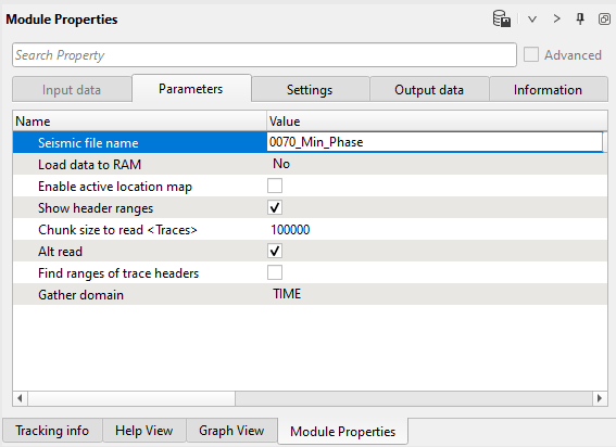
1) Read seismic traces. Load seismic data set 0070_Min_Phase.
Parameters:
2) Sort traces - by SOURCE. Here we need to sort seismic traces for Seismic loop, not for SCAC (no sort is required for it). Therefore, add Sort traces module and set SOURCE_LINE, SOURCE_SP, RECEIVER_LINE, RECEIVER_SP (or just SOURCE_SP, because the input seismic data set was sorted by source sequence) for sorting as it is shown below:
Parameters:
3) Seismic loop. Connect trace headers vector (Input sorted headers) from the Sort traces module output and seismic (Input SEG-Y data handle) from Read seismic traces. Select some source point for testing as shown in the parameters:
Parameters:
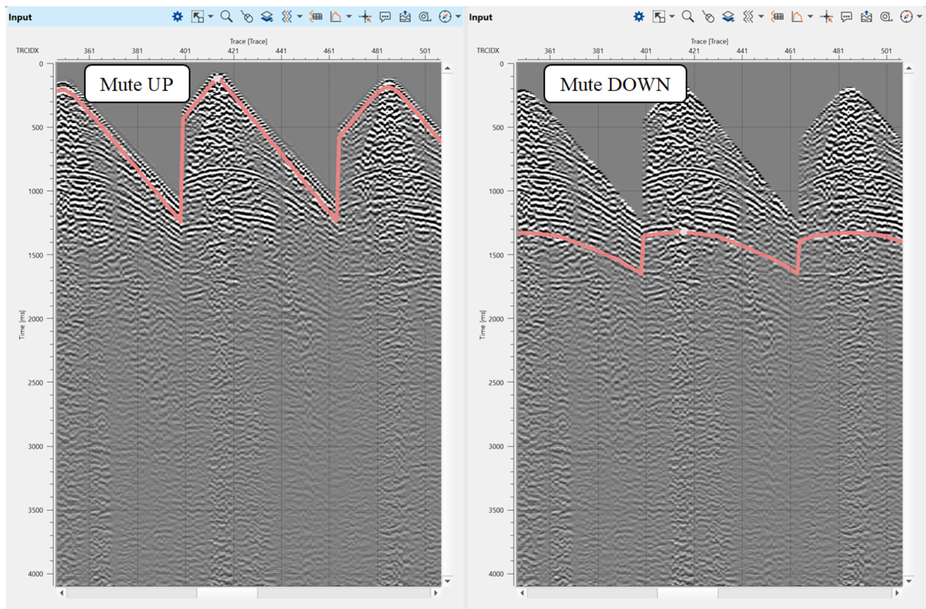
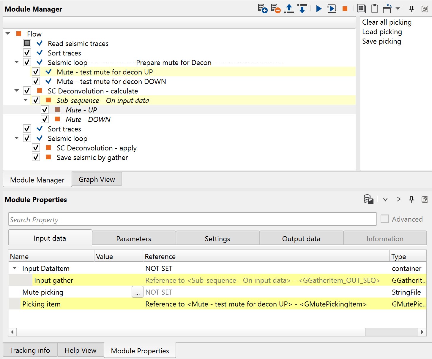
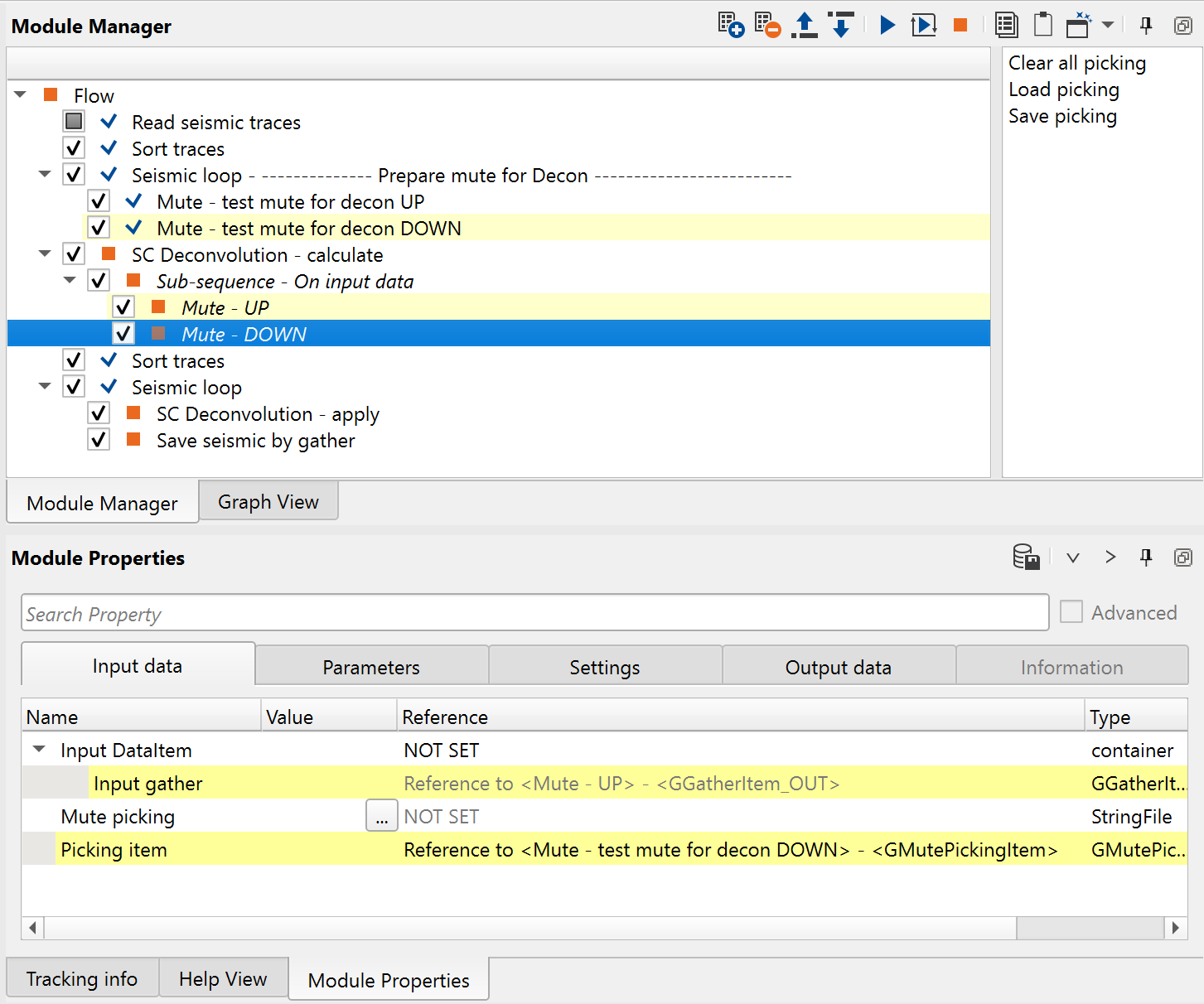
4-5) Mute - test mute for decon UP/DOWN. How to define windows for calculation: use Sub-sequence process in SC Deconvolution - calculate for cutting unwanted parts of the gather and save only signal area for spectrum calculation. Put two Mute modules into Seismic loop and create UP mute and DOWN mute to remove unnecessary part of the traces for deconvolution filter calculation:
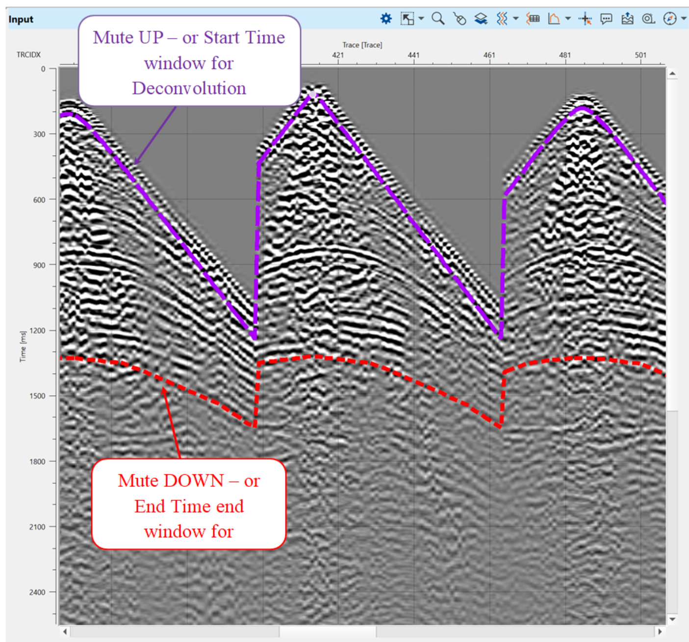
Or you can merge two mute function and show them on the one seismic gather. Use drag'n'drop function and get/drag Curve from the Mute module and put it on the gather. Change visual settings of the mute curves and you will have this view:
6) SC Deconvolution - calculate. The first step in deconvolution is calculation of autocorrelation, spectrum and filters. Add SC Deconvolution - calculate module and define all necessary inputs items and parameters. Add 2 Mute modules into sub-sequence and use mute functions from the previous tests:
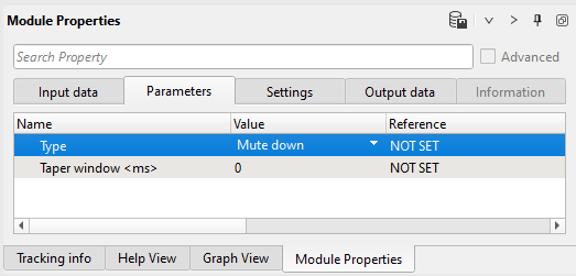
Change type of muting (Mute down):
Parameters:
Next, define decon calculate parameters as it is shown below and execute this procedure:
Parameters:
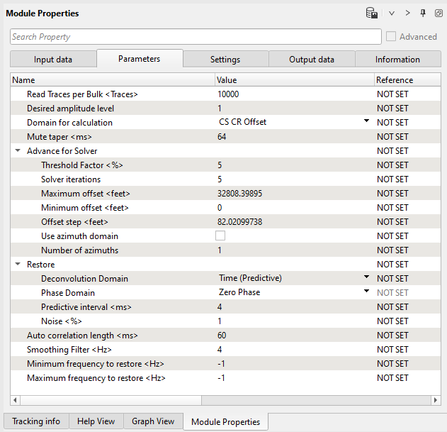
Mandatory decon parameters:
We have three different domains for calculation:
Common Shot Common Receiver
Common Shot Common Receiver and Offset
Common Shot Common Receiver Offset and Bin
Time (Predictive)
Frequency
If the user select the Time then, the Phase domain will be Zero Phase Only else it will be either Zero Phase or Minimum Phase
---------------------------------------------------------------------------------------------
![]() Notice that SC Deconvolution modules may be used for SCAC as well
Notice that SC Deconvolution modules may be used for SCAC as well
----------------------------------------------------------------------------------------------
| DECONVOLUTION [STEP 2 - APPLYING] |
6) SC Deconvolution - apply. The second step is filter applying. Add SC Deconvolution - apply inside the Seismic loop module, add all vista groups to the work area and run one source gather in a loop just for testing. We are going to apply only deconvolution without amplitude correction, because it is already have been done on a SCAC step (1 iteration). Add SC Deconvolution - apply inside the Seismic loop module, add all vista groups to the work area and run one source gather in a loop just for testing. We are going to apply only deconvolution without amplitude correction, because it is already have been done on a SCAC step (1 iteration).
Connect FrequencyResponseSpectrumItem from the SC Deconvolution - calculate module:
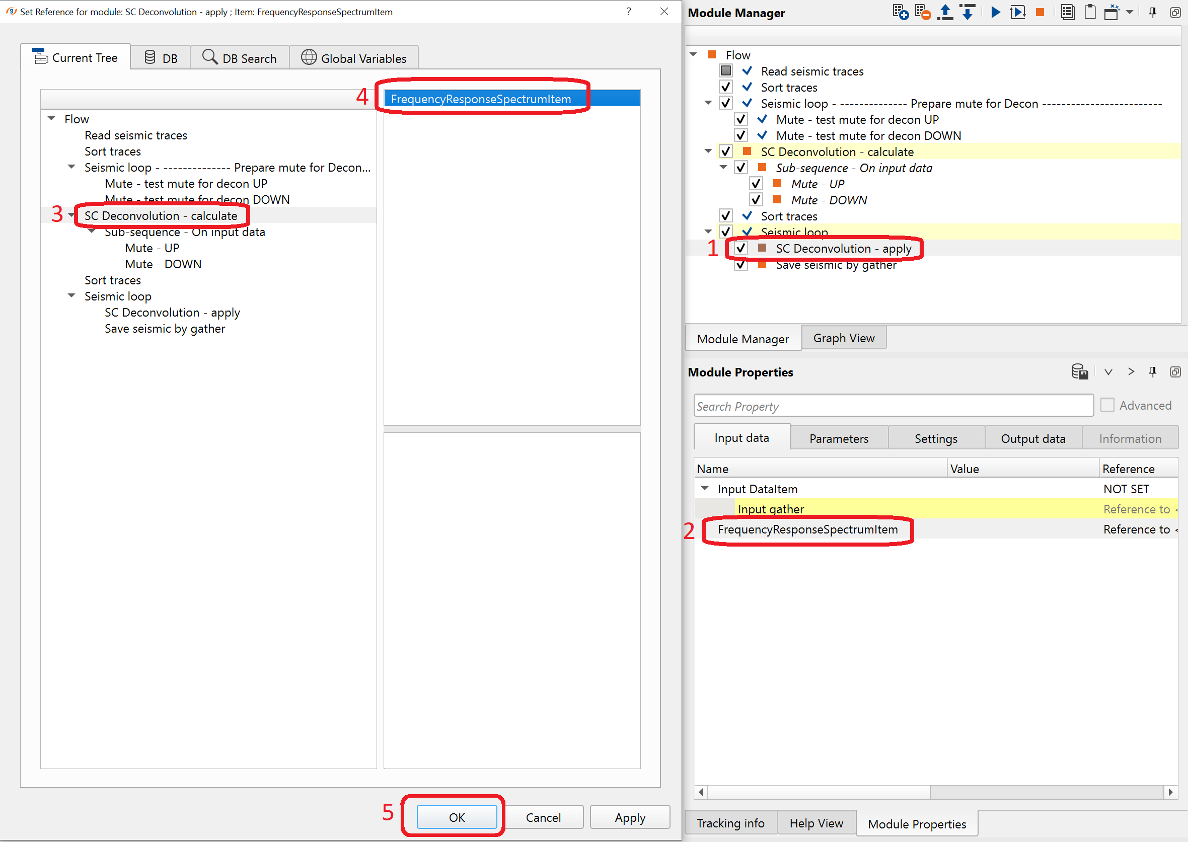
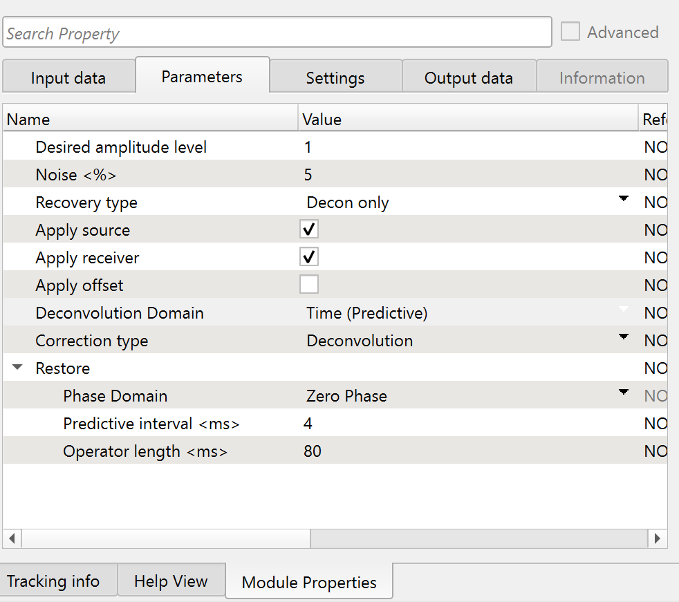
Define the following parameters and run one gathers again, do some tests, for example try to change Noise <%> (pre-whitening factor): please make a note of it that the recovery type has two options: Decon only & Decon and amplitude recovery. Since we are working on SC Deconvolution, we proceed with Decon only option.
Parameters:
The calculated operators from the SC Deconvolution - calculate module will be applied on the individual shot or receiver based on the application domain we choose.
In the SC Deconvolution - apply module, we have Common Shot (CS) Common Receiver (CR) and Common Shot (CS) Common Receiver (CR) Offset domains are available. Based on the option we selected during the calculation we select the same domain to apply the calculated operator values.
In the input data tab, connect the appropriate Frequency Response Spectrum Item from the SC Deconvolution Calculate module.
Main decon parameters definition:
Noise: % white noise, pre-whitening.
Frequency
If the user select the Time then, the Phase domain will be Zero Phase Only else it will be either Zero Phase or Minimum Phase
Spectral Equalization
Deconvolution
Select the appropriate domain: Zero Phase or Minimum Phase
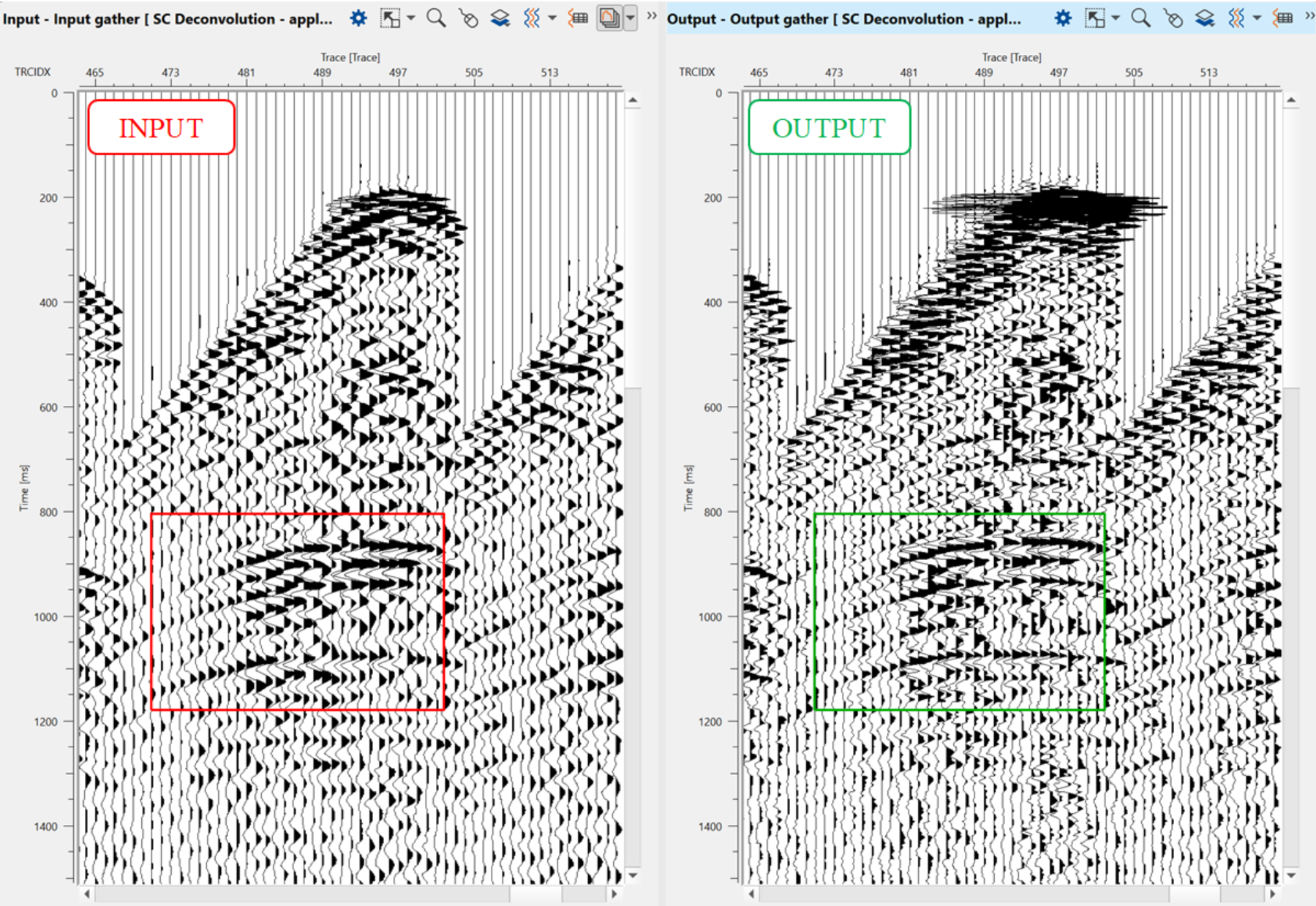
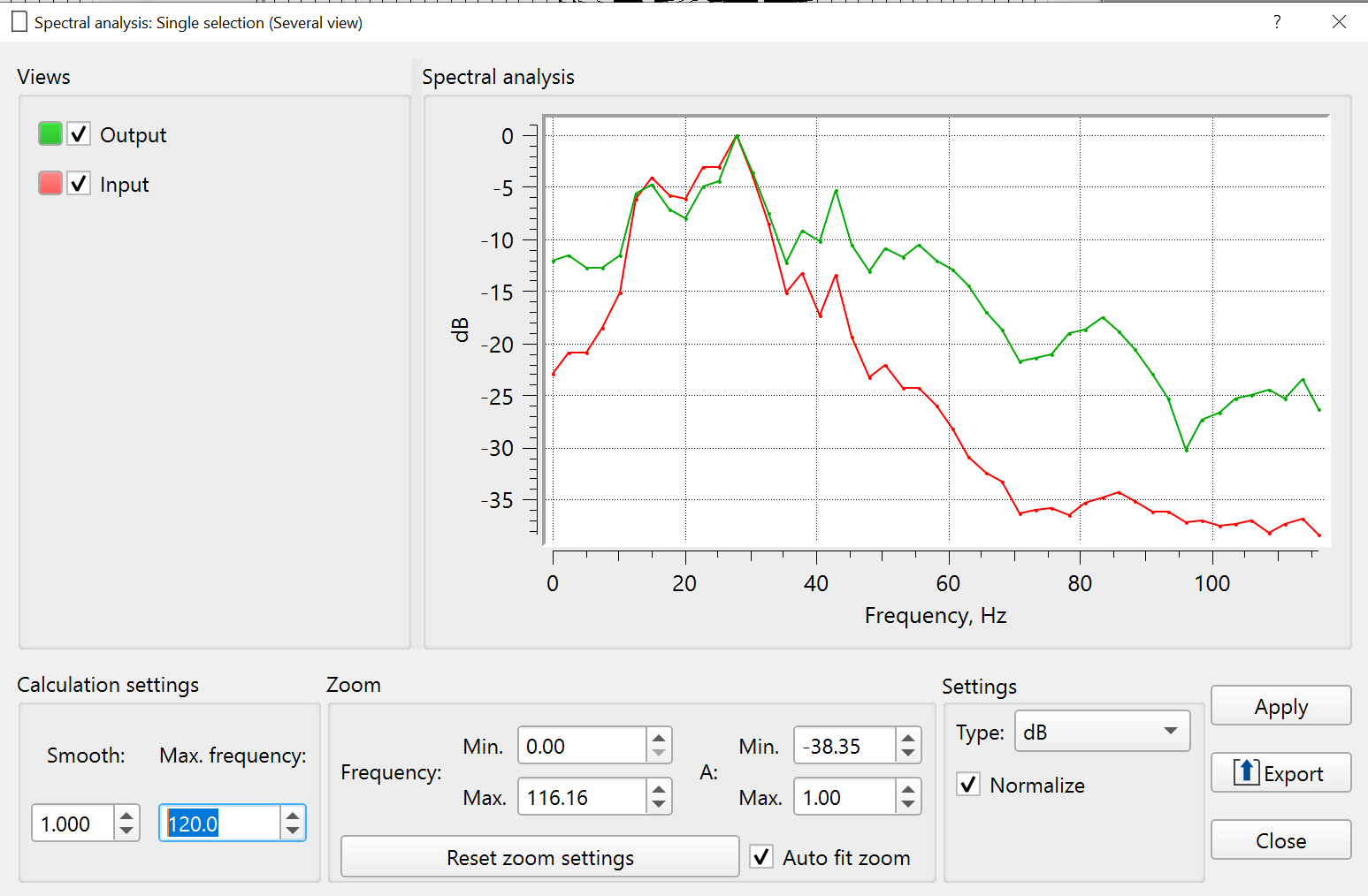
Execute a module SC Deconvolution - apply, open a vista view and check gather before and after deconvolution and its spectrums:
7) Save seismic by gather. Define a name for output data set 0060_SCDecon in Save seismic by gather module . Execute Seismic loop for the entire data (press ![]() button from upper menu).
button from upper menu).
 If you have any questions, please send an e-mail to: support@geomage.com
![]() Surface Consistent Deconvolution: Calculate and Apply - Geomage g-Platform - YouTube
Surface Consistent Deconvolution: Calculate and Apply - Geomage g-Platform - YouTube