 | VELOCITY ANALYSIS (MANUAL PICKING) |
|
<< Click to Display Table of Contents >> Navigation: Tutorials > Seismic Processing 3D LAND >
|
In seismic processing one of the key steps is velocity analysis which is used for compensation of distance between source and receiver. This distance or offset has unwanted influence on travel time, so we need to apply normal move out (NMO) corrections to bring reflections on zero-offset, to make reflection's hodograph flat. Seismic wave speed is usually called velocity, and the estimation process is called velocity analysis. In time processing, we estimate the stacking or migration velocities and in the case of depth imaging, we need to build the velocity model with using different kinds of methods like tomography, FWI and so on.
Create a new workflow 0080_Velocity_analysis_(iteration 1, manual picking):
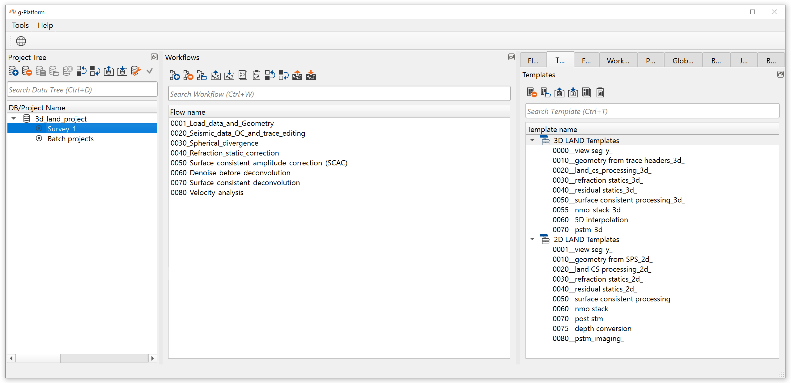
Add all necessary modules:
1. Read seismic traces - load traces after deconvolution step
2. Load item - load refraction static
3. Stack imaging - stacking velocity estimation, muting, CMP trace stacking
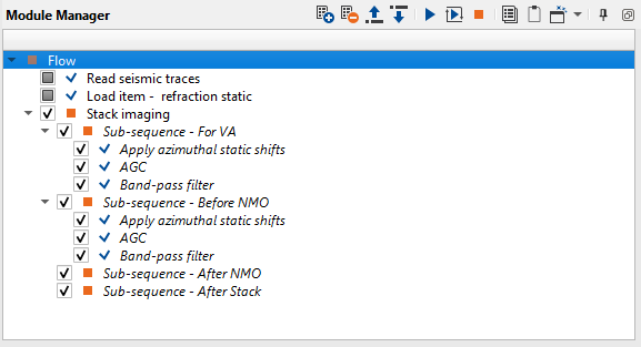
1) Read seismic traces. Define the input seismic file parameter 0060_SCDecon:
Parameters:
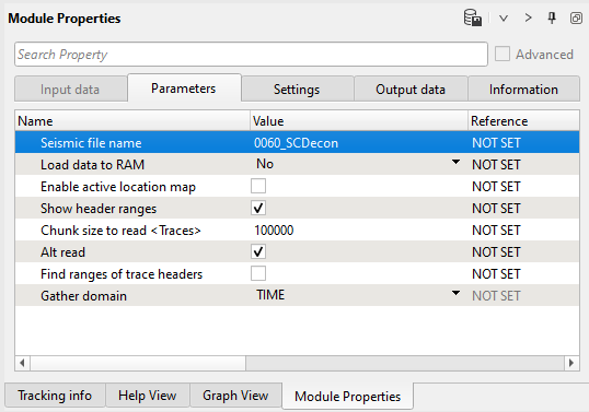
2) Load item - refraction static: load refraction static library from DB. Define an input file name Refr_stat_conv:
3) Stack imaging. This module is complex interactive application for velocity analysis, creating mute function, stacking CMP gathers. Input data is gathers in any sorting, without NMO corrections. Get input data items from Read seismic traces.
Input data:
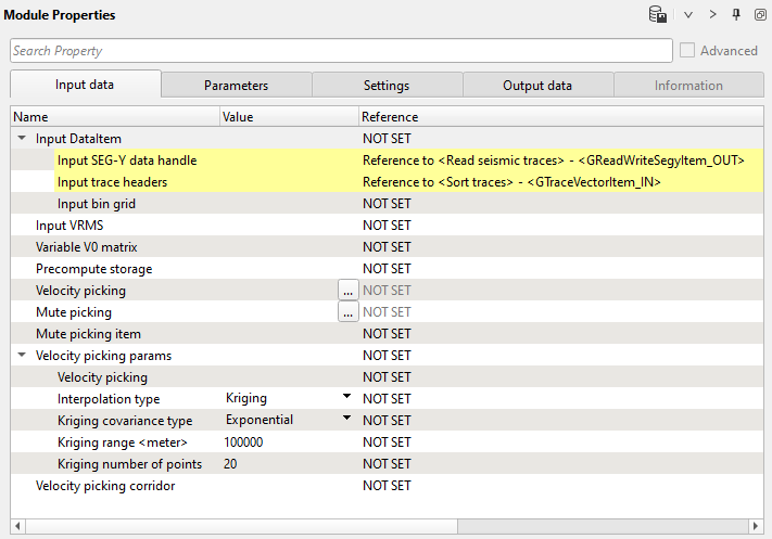
Input data definition:
| Input Data item |
| Make a reference to the Read seismic traces or any other module which has prestack seismic data as an input. This is the only mandatory reference input data requirement for Stack Imaging. Other input data items are optional. |
Input VRMS
Provide the Input VRMS in case we have an external velocity model or using a velocity model as an input gather. In case we provide the input VRMS then the we should change the Velocity usage option in the Parameters accordingly.
Variable V0 matrix
In case the replacement/near surface velocity V0 is variable then the user should provide the velocity matrix as an input. Accordingly, we should check the option in Velocity Analysis parameters.
Precompute storage
Provide a storage name for precomupting the velocities. Use in case of large surveys.
Velocity picking
Provide the previously picked internal velocity file (if available) otherwise ignore it. Once we finished picking the velocities and saved them, then the saved path is displayed here.
Mute picking
Provide the previously picked internal mute file.
Mute picking item
Reference to any mute picking module and using mute function in current module.
Velocity picking params
parametrization for velocities interpolation.
Velocity picking corridor
This is mandatory in case the user wants to pick the velocities automatically. The user must provide the velocity corridor file.
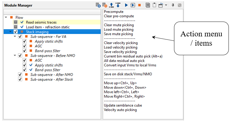
Pay attention on what is inside Stack imaging module, it is sub-sequence. Sub-sequence helps to avoid creating a separate workflow to apply an AGC or Deconvolution or other processing modules, we just simply insert those modules in the sub-sequence inside the main module. Put modules inside the sub-sequence as shown below:
•Sub-sequence - For VA: processing for velocity analysis, i.e. apply some procedures like band-pass or AGC, and then velocity spectrum is calculated;
•Sub-sequence - Before NMO: processing before applying NMO corrections to gathers, for example we can apply static corrections;
•Sub-sequence - After NMO: processing before applying NMO corrections to gathers, for example we can apply denoise procedures;
•Sub-sequence - After Stack: processing after stacking CMP gathers, for example we can apply denoise procedures or spectrum balancing.
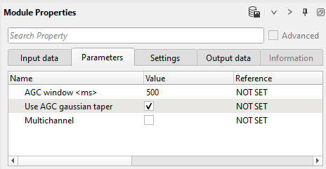
AGC parameters:
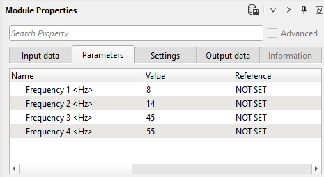
Band-pass filter parameters:
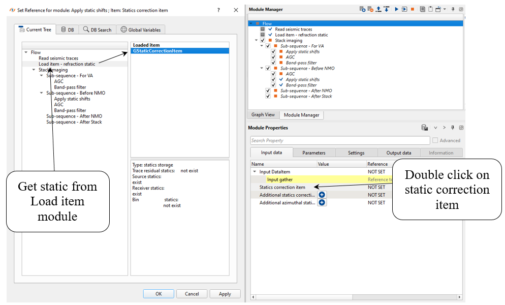
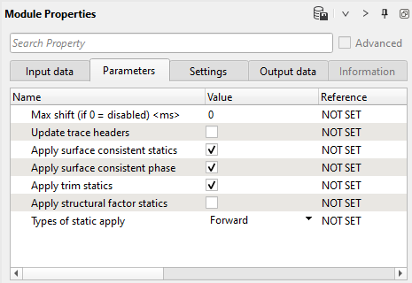
Apply azimuthal static shifts input data and parameters:
If we look at the action items menu on the right hand side of the Stack Imaging module, there are many options like loading, saving and clear libraries (velocity, mutes), auto-picking mode and other. Of course some functions are optional and we don't need to use all of them, but some of them are often used:
Read parameters definition below just for common understanding:
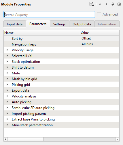
Sort by:
This parameter defines how to sort the input data. Default: by offset. Upon expanding the menu, we have few options:
Offset - This option sorts the data in offset domain.
Absolute Offset - This sorting method considers the absolute offset.
As is - It sorts the data as per the input data.
Navigation keys:
It determines how the user wants to navigate inside Stack Imaging to pick velocities or mutes. Here we have two options:
Net - If the user selects this option, the user have the limited ability to navigate through the data i.e., the user can go to a particular defined point only.
| All bins - This option allows the user to navigate through all the bins that are available. It means, the user can select any random location( in this case bin) and pick | either the velocities or mute. |
Velocity usage:
It determines what kind of velocity we can use:
| Consider only picks on current line - By default, it is unchecked. If checked, it will consider consider the velocity picks only to that particular inline/xline and | update the stack accordingly. |
| Use External VRMS - In case the user have the velocity information in an external format like SEGY, then the user can use this option to consider the external | velocity information in stack creation. If the user chooses this option, they must provide the Input VRMS at the Input data tab. |
Use pickets - The velocities are interpolated along the stack line/crooked line. Otherwise, the velocities are interpolated using X, Y coordinates.
Selected IL/XL:
Here we can define or choose a specific inline/xline.
Selected inline - Specify the inline number which needs to be created
Selected crossline - Specify the crossline number to be created and/or pick velocities. In case of 2D data, it will be crossline.
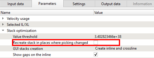
Stack Optimization:
Inside this, we can determines how to optimize the stack:
Value threshold - By default it calculates from the input data and the user doesn't need to provide anything here. Ignore this parameter.
Recreate stack in places where picking changed - It will ONLY creates the stack where the velocity picks were changed/edited. Rest of the stack will remain the same.
GUI stack creation - We can choose whether we want to generate only an inline or crossline or both.
Show gaps on the inline - By default, it is checked. If there are any data gaps in inline/crosslines it will display them.
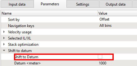
Shift to datum:
We can shift the data to final datum or keep it as it is (at topography). As we mentioned earlier, in g-Platform, we estimate velocities from the topography level. In Binning 2D module, we provided created a smoothing topography which is representation of the floating datum. Here we are smoothing the CMP elevations only. The source and receiver elevations remain same:
Shift to Datum - By default unchecked. If the we would like to shift the data to datum then we need to check this option and provide Datum value.
Datum(meter) - If the previous option is checked, then we should provide the Datum value to shift the data from current datum to the final datum.
Mute:
This parameter determines the mute taper value in case we have mute function.
Taper window (ms) - Tapering between muted and saved zones.
Mask by bin grid:
This is helpful in case of 3D to crop some of the minimum and maximum offsets while creating the inline/crosslines or the volume.
Min offset mask apply - If checked, define the minimum offset for all the CMPs to crop them, means it won't be used in the final stack.
Max offset mask apply - By default, unchecked. It is similar to the Min offset mask. If checked, define the maximum offset to crop.
Picking grid:
We can define at what interval we should pick the velocities. In case of 2D, if we want to pick the velocities at 2 km interval and the CMP
interval is 12.5 m then we need provide 160 (2000/12.5 = 160) as inline/cdp increment value or step size.
Inline/CDP increment - Provide the inline increment step size. In case of 2D, provide the CDP increment step size as explained above.
Crossline increment - Provide the crossline increment step size.
Export data:
This parameter is purely reading the data while exporting the data.
Read bins bulk size(Bins) - Define the number of bins to read in a bulk. By default 200.
Velocity analysis:
This is the main component of creating the semblance display. Inside the Velocity analysis, the user should define various parameters to generate the semblance, Common Offset (CO) gather, NMO stretch factor etc.
Use variable V0(matrix) - In case the near surface/replacement velocity is varying and not constant the user can check this option to consider Variable V0. If this option is checked, the user must provide the Variable V0 matrix at the Input data tab.
Replacement velocity (m/s) - Specify the replacement or near surface velocity value for datum shift.Set this value prior to beginning of the velocity picking.
Start velocity (m/s) - Define the starting velocity value for creating the semblance.
Ending velocity (m/s) - Define the ending velocity value for creating the semblance.
Velocity increment (m/s) - Specify the the velocity increment step size. By default 50 m/s.
Semblance smoothing window (ms) - This value defines the smoothing of the semblance display. Higher window makes the semblance more smooth which is not ideal an ideal scenario but it depends on the input data quality. Default parameter value of 50ms works good.
Stretch factor (%) - This parameter determines the NMO stretch factor. By default 50. If the user changes this value then the user can to observe the changes in the Velocity analysis window (Semblance display), Current NMO Seismogram display. Once the user executes the Stack Imaging module with the updated Stretch factor then the stack will be created using user defined NMO stretch factor.
Smoothing parameter Y velocity (Samples) - Default value is 10. Define the number of vertical samples to define the velocity smoothing.
Normalization window (ms) - Default 100 ms. This parameter is used for normalization of the semblance display.
Semblance resolution - Select the type of resolution. We have 3 options, Normal (By default), Low and High. By meaning of the Low and High, it decreases/increases the semblance resolution. Depending upon the input data quality the user can select the appropriate semblance resolution.
Show CO gather - By default unchecked. If the user wants to display the Common Offset (CO) gather then check this option.
Semblance improvement type - By default Average. Select the appropriate type from the available options to adjust the semblance calculation to improve the semblance display.
Super gather radius inline (VA and CO) - Define the super gather radius in inline direction
Super gather radius crossline (VA and CO) - Define the super gather radius in crossline direction
Show CO gathers - If this option is checked, it will display the Common Offset gathers with different options.
CO with constant step - Displays the CO gathers with a constant CO offset step size. The step size should be defined at CO radius (meter).
CO with original geometry - It will display the CO gathers at original geometry.
CO radius (meter) - Define the Common Offset step size.
CO gather abs offset sort - By default unchecked. If checked, it will sort the CO gathers in absolute offset.
----------------------------------------------------------------------------------------------------------------------------------------------------------
![]() The next two groups of parameters are used for auto-picking, so don't use it on current step (manual picking).
The next two groups of parameters are used for auto-picking, so don't use it on current step (manual picking).
We will discuss it in the second iteration of velocity analysis (automatic picking).
----------------------------------------------------------------------------------------------------------------------------------------------------------
Auto picking:
This part of Stack Imaging module provides auto picking. We should provide the following parameters.
Use semiautomatic picking - by default it is unchecked. If it is checked, it will adjust the user picked velocities to the maximum semblance value.
Min velocity deviation (%) - percentage of minimum velocity deviation from the input 100% velocity.
Max velocity deviation (%) - percentage of maximum velocity deviation from the input 100% velocity.
Max time deviation (ms) - maximum acceptable time deviation. It's time window for single auto-picking.
Inline/cdp start autopick - starting inline (in case of 3D) or CDP (in case of 2D) number for auto-picking.
Crossline start autopick - starting crossline number to auto-picking.
Inline/cdp step autopick - this parameter is for residual auto picks only. Provide the inline/CDP step size.
Crossline step autopick - crossline step size for residual auto pick.
Detect points sensitivity - spectrum sensitivity for auto-picking.
Semblance threshold - when semblance calculation is done, it is either 1 or 0. If the correlation between any two given points is 1 then we have a very good semblance otherwise we have no semblance which means 0. In the case of automatic velocity picking, when the user provides a semblance threshold value of 0.5, then it will ignore picking the velocities anything below 0.5 semblance threshold.
Semb. Cube 2D auto picking:
This is used for auto picking the velocities based on velocity corridor.
Inline/CDP step autopick - this is the main parameter at what interval the automatic velocity picking should be done. If user provides the Inline/CDP auto-picking step a= 25, then it will automatically pick the velocities at every 25-th Inline/CDP.
Aperture - number of neighboring BINs to analyze the semblance for the current picking location.
Slope (%) - this parameter relates to the reflectors. If the reflectors are straight then the slope can be less otherwise the slope can be a higher value.
Multiplied super gather radius inline - It is number of bins used to analyze the semblance and multiplied by the user defined factor. Higher multiplication factor means less events for auto picking. The higher multiplication factor stabilizes the semblance laterally.
Time smoothing window (ms) - Provide the smoothing window smoothing velocity function. The larger smoothing window the smoother velocity function.
Time step (ms) - Provide the time step at what interval the automatic picking should take place.
Corridor width (m/s) - Define the velocity corridor width.
| Import picking params: |
Magnet picking points to geometry - By default, it is checked. The main objective of this parameter is to detect or select the exact Inline/CDP/Cross line location in the location map or location map inline/crossline. In case the user picks somewhere on the location map but not exactly at the desired position, based on the
Magnet max distance, it will automatically searches and selects that position on the location map. Magnet max dist (meter) - Define the magnet maximum distance to search for the point.
Extract base Vrms to picking
This parameter is directly related to Input VRMS in Input data tab. When the user reads the external velocity or internal velocity by gather, it will extract the information based on the following parameter values.
Geometry step (meter) - Provide the geometry step size to convert/extract the input Vrms into internal velocity format.
Detect points sensitivity - velocity point sensitivity.
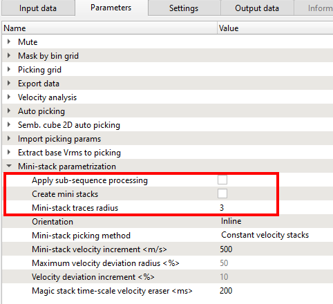
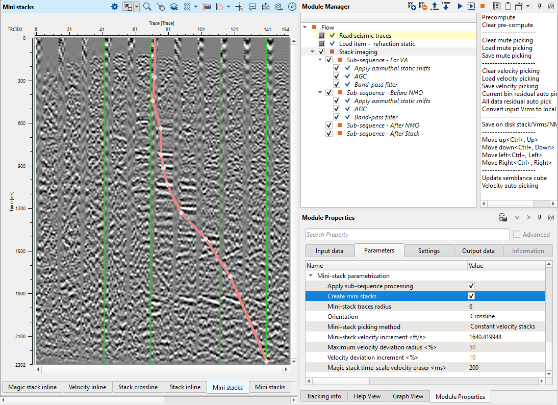
Mini-stack parametrization:
Mini-stacks are also knows as CVS (Common Velocity Stacks). These are very useful in helping the user to get an idea about the overall velocity range and it's trend. There are few parameters needs to be filled to create these Mini-stacks in g-Platform. By default, the Mini-stacks display is not available in Vista Groups-> 2D groups or 3D groups. The user must separately add them.
Apply sub-sequence processing - By default unchecked. If checked, it will automatically apply the sub-sequence processing steps involved in VA/Before NMO.
Create mini stacks - By default unchecked. In order to create the Mini-stacks, the user must check this option to generate the Mini-stacks.
Mini-stack traces radius - Define the number of traces (CMPs) are considered in creation of the Mini-stacks.
Orientation - Choose the Mini-stack orientation. By default, Inline. The user can choose inline or crossline from the drop down menu.
Mini-stack picking method - When the user wants to pick the velocities on Mini-stacks, the user have two options to choose from.
Constant velocity stacks - By default, this is the option wherein the stacks were created using a constant velocity defined by user at Velocity analysis parametrization.
Current interpolated stacks - The user can to pick the velocities on interpolated stacks.
Mini-stack velocity increment (m/s) - Provide the velocity increment. From one Mini-stack panel to another Mini-stack panel, the velocity varies from the user defined value. This option is active when the Mini-stack picking method is Constant velocity stacks.
Maximum velocity deviation radius (%) - Define the maximum velocity deviation. This option is active when the Mini-stack picking method is Current interpolated stacks.
Velocity deviation increment (%) - percentage of minimum velocity deviation from .
Magic stack time-scale velocity eraser (ms) - interactive velocity eraser.
------------------------------------------------------------------------------------------------------------------------------------------------------
![]() Velocity picking within the Stack Imaging module is not corrected to final datum. In g-Platform, we pick velocities on the topography and shift it to the final datum if necessary. In that case, we should use Shift to datum option inside the Parameters tab. Also we can perform this task by adding the Shift to datum module under the Sub-sequence - After stack. The velocities are still at Topography. Only the stack shifted to Final datum.
Velocity picking within the Stack Imaging module is not corrected to final datum. In g-Platform, we pick velocities on the topography and shift it to the final datum if necessary. In that case, we should use Shift to datum option inside the Parameters tab. Also we can perform this task by adding the Shift to datum module under the Sub-sequence - After stack. The velocities are still at Topography. Only the stack shifted to Final datum.
![]() During NMO application, the source and receiver elevation statics are calculated automatically by shifting to CMP (Bin) elevation, and applied to the seismic trace
During NMO application, the source and receiver elevation statics are calculated automatically by shifting to CMP (Bin) elevation, and applied to the seismic trace
-----------------------------------------------------------------------------------------------------------------------------------------------------
Since we are working on a 3D data set, we should select the 3D groups and the following Vista items will be displayed as shown below. We can arrange those Vista items as we want. In 3D groups, we have Stack inline, Crossline, Velocity inline, crossline, Velocity analysis (Semblance), Current seismogram (Before NMO), Current NMO seismogram (After NMO), Location map X, Y and Location map Inline/Crossline:
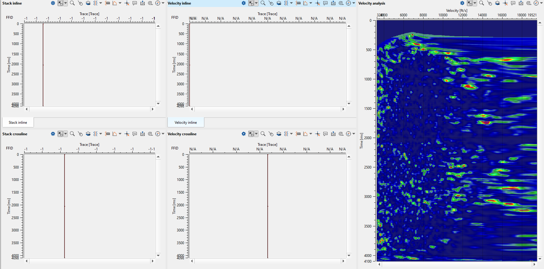
In the above image, we can see the stack inline/cross and velocity inline/crossline that are empty. We should pick the velocities and execute the Stack Imaging module to generate these displays.
----------------------------------------------------------------------------------------------------------------------------------
![]() Please make a note of it that the mini-stacks are not added to the by default.
Please make a note of it that the mini-stacks are not added to the by default.
If we need it in the current display, then we can select the Vista Groups-> Mini stacks-> Add view.
----------------------------------------------------------------------------------------------------------------------------------
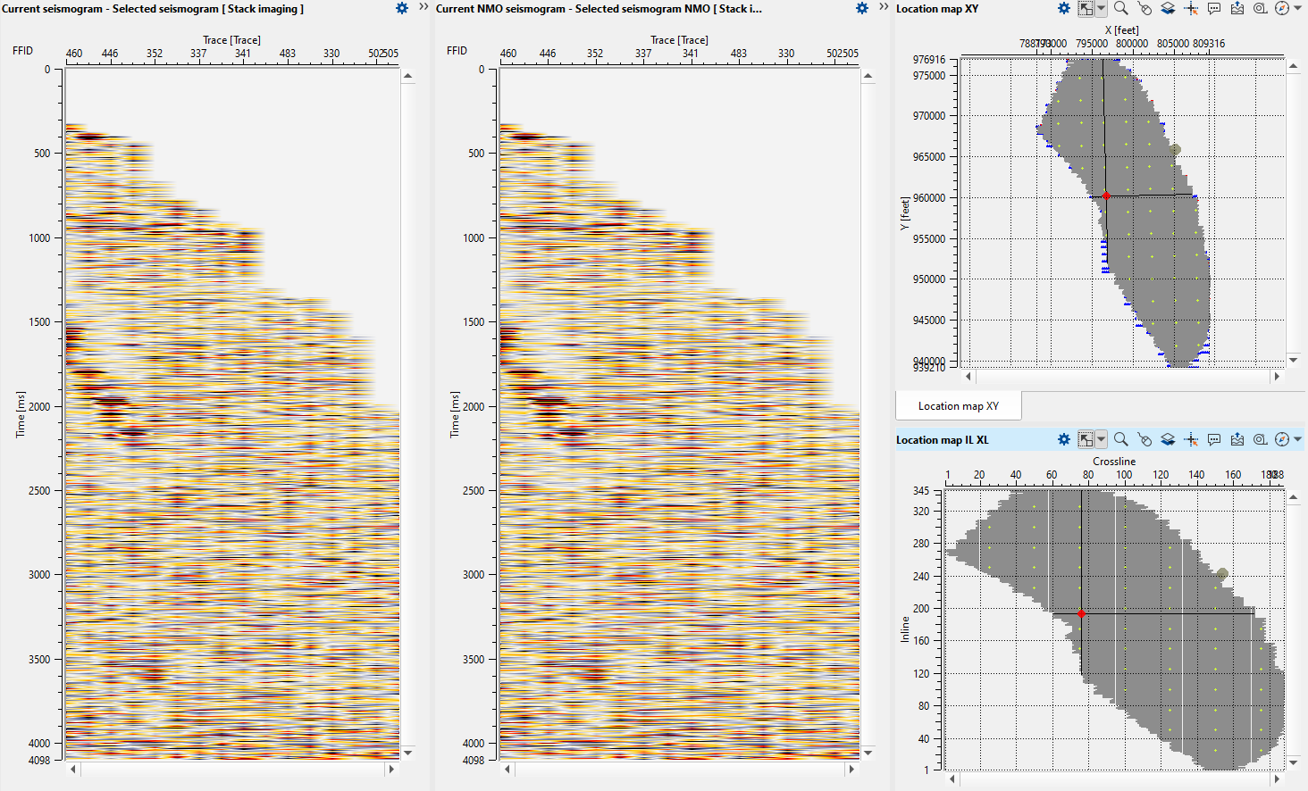
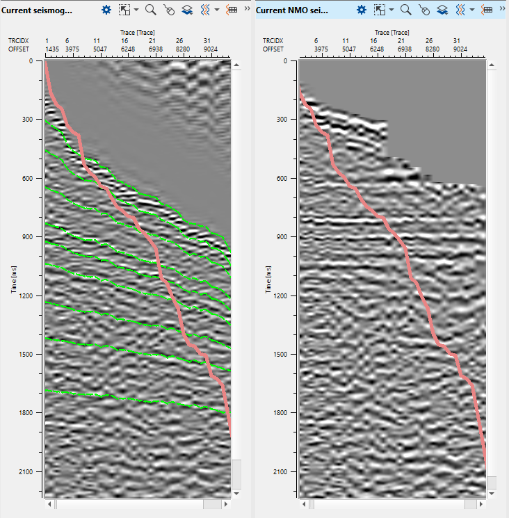
To pick velocities, we should click on the velocity analysis window panel. It will come up with three lines. The two yellow lines are basically the Velocity corridor (for auto picking) and the middle line is the Current velocity pick trend. Once we start picking the velocities, a red line appears which is the Interval velocity. In middle of the section, now we can see the gather before and after NMO correction.
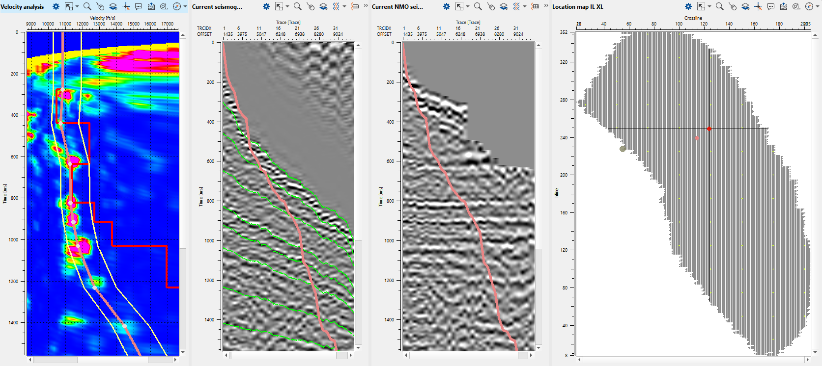
The green lines on the Current seismogram represents the travel time curves. If we want to hide them it can done from the View properties window of the Current Seismogram.
The red line on gathers is mute function for stacking (you can pick it on fly or load it).
Depending on the parameters, we can pick the velocities either randomly by selecting any point from the location map or step-grid which was defined in the Parameters tab. To move left, right, up & down, we can look at the action items menu and use the short cuts to move around.
To remove any bad picks, we should hold MB3 or RMB and draw a polygon. Whatever is in the polygon area it will be removed.
To edit any picks, hold MB1 or LMB and drag the pick to any new position.
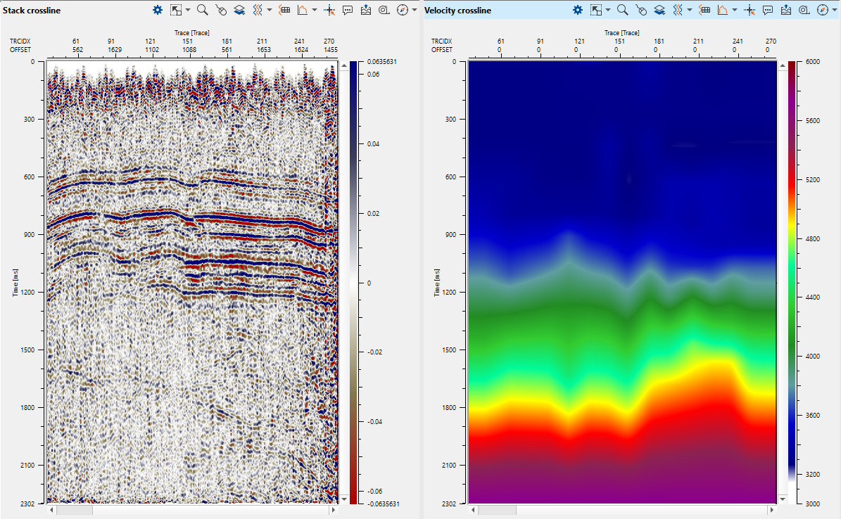
As we are picking more locations, Velocity inline keeps updating, however we still can't see the Stack inline. To generate the Stack inline, we should execute the Stack Imaging module either by double clicking on Stack Imaging module or press the Execute module ![]() icon.
icon.
Check result, for instance: stack and velocity sections.
Residual velocity picks:
------------------------------------------------------------------------
![]() These are residual auto picks only (not auto picking!).
These are residual auto picks only (not auto picking!).
------------------------------------------------------------------------
In case we want to do a residual velocity picking (bad picks corrections), then we should go to the Action items and choose the option Current bin residual autopick for the current bin position only.
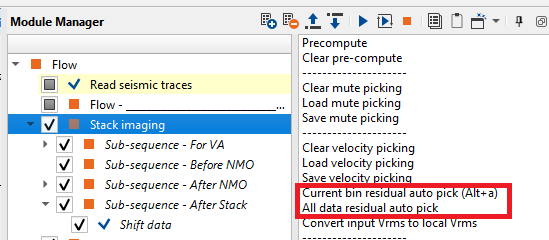
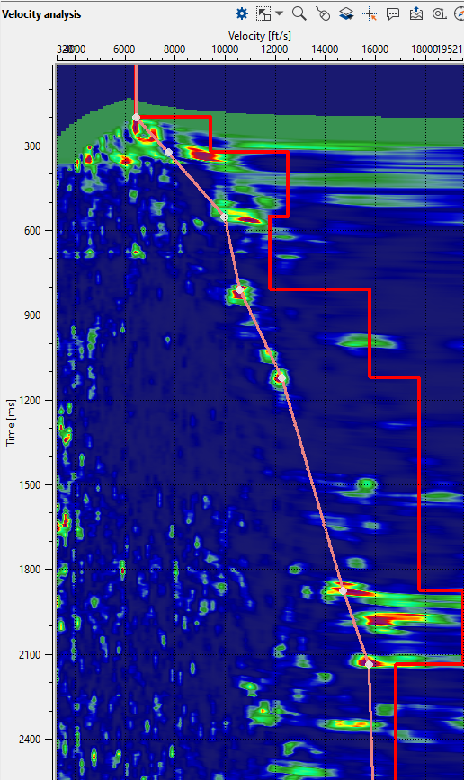

In the above image, the first velocity analysis window displays picked velocities. To the right of the velocity analysis, we have another velocity analysis window with Residual autopick velocity analysis.
Similarly, to pick the velocity residuals for the entire line then we should select the option All data residual auto pick. Select Current bin residual auto pick to automatically pick the residuals for the current bin position.
We mentioned at the beginning of the Stack Imaging module that, this module can be used to pick a mute function (CMP/CDP domain). To pick a mute on the Current NMO seismogram, click on the gather and it should come up with the mute lines. These mute lines are visible on both Current seismogram & Current NMO seismogram.
To remove the picks, it is similar to the velocity picks where we should hold MB3 or RMB and draw a polygon. As soon as you release the mouse, it will remove the pick. To move the picks, it should be MB1 or LMB.
Activate mini-stacks option for calculation a set of mini-stacks for velocity analysis:
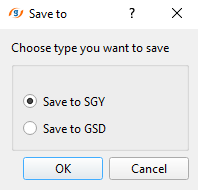
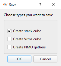
Also we can create the Stack/Vrms/NMO from the Stack Imaging module. In order to create and save it, we should choose the option Save on disk stack/Vrms/NMO from the action menu. As soon as we click the option, a pop-up window opens with the default option as Save to SGY. Click OK. Now another pop-up window opens up with the different options. Here we can select one or all of them and click OK. Finally, a file browser window opens and we should provide a name. Depending on the choice we have selected, it will suffix the names to the respective a data type with an extension of SGY to the data set.
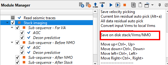
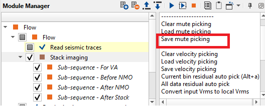
Click on Save velocity picking and/or Save mute picking options from the action items menu of Stack Imaging module to save picked velocities and/or mutes.
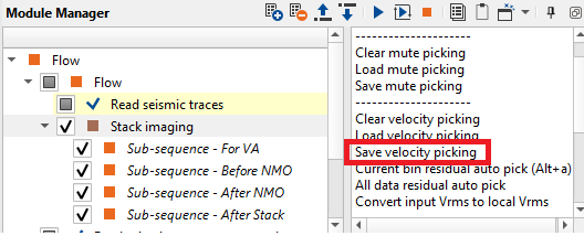
Save velocity on a disk with following name: Velocity_iter_1.
 If you have any questions, please send an e-mail to: support@geomage.com