In g-Platform software, we can do VSP processing using the module VSP Processing.
Within the module, the user can able to do pre-processing (inside the sub-sequence) without any additional pre-processing steps prior to the VSP processing. In the following sections, we are going to describe the procedure to start working on VSP data and it's processing steps .
Input : VSP data
Output: CDP stack (Depth & time converted)
Velocity model
In simple steps, the procedure is as follows.
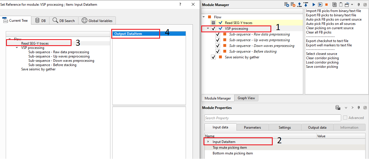
1. Read and connect the input data to VSP processing module.
2. Pick first breaks. Once the first break picking done, we can pick the corridor(top and bottom mutes).
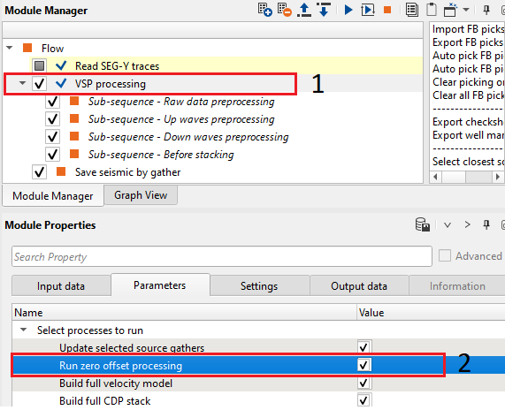
3. Double click on VSP Processing module to generate the Well stack and Well velocity model. By default "Run zero offset processing" option is selected in the "Select processes to run" parameter
4. Execute/Double click on VSP processing module to generate the final velocity model, full CDP stack(s).
This is the overall cycle of VSP processing and it's final output(s).
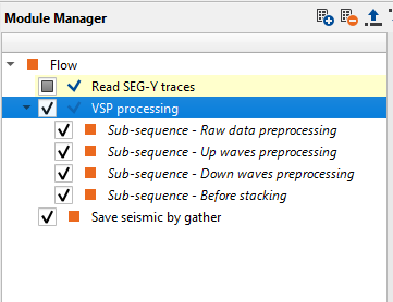
Ideally there are only three module(s) required to create the VSP workflow as shown below.
VSP Processing procedure:
Read the input data and connect the corresponding input data to the VSP Processing module.
Once the data read, the user can right click on VSP processing module and generate the vista items from the Vista Groups -> All Groups -> In a new window.
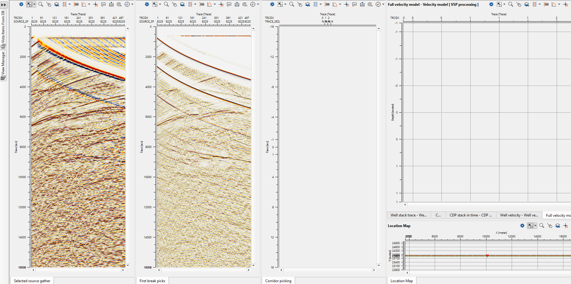
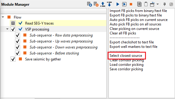
When we launch the Vista items, we can select any shot gather from the location map and it will display the selected shot gather as shown above. However, if the user prefers to pick the shot gather which is close to the well, then they can choose the option "Select closest source" from the action items and it will display the closest shot near to the well.
Now the user can able to do the first break picking. In order to do that, the user should select the "Auto pick FB picks on current source" from the action items menu. It will display the FB picks based on the user defined parameters under "First break auto picking" parameters tab. In the following images, you can see the shot before and after automatic FB picking.
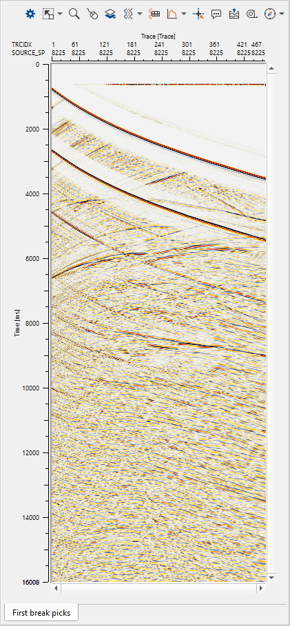

QC the quality of the first break picks and adjust the parameters if it is necessary and try again. Likewise QC FB picks and choose the option "Auto pick FB picks on all sources" to pick first breaks on all sources. QC them thoroughly before proceeding further. After this, it generates the NMO gather using the First break pick times.
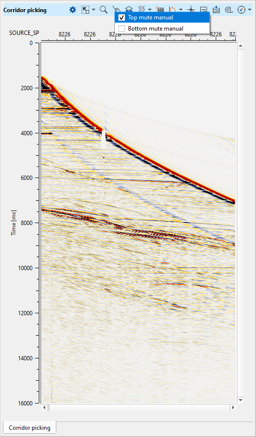
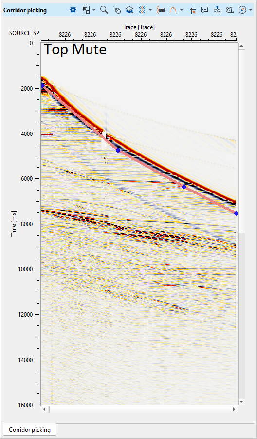
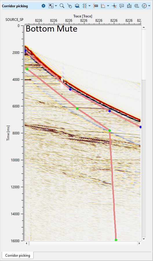
In the next stage, we are going to pick the corridor. For picking the corridor, the user should go to the Corridor picking (Top & bottom mute) shot display window and pick the corridor(Top and bottom mute) as per their requirement. To pick Top/Bottom mute, the user should go to Control item icon ![]() and select the desired options from the Control item.
and select the desired options from the Control item.
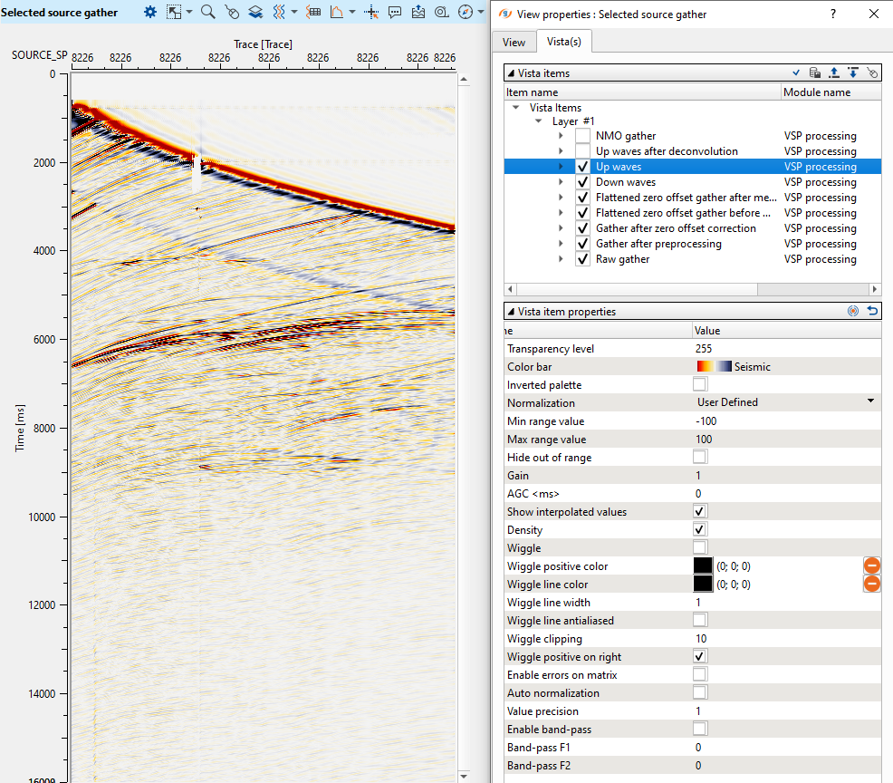
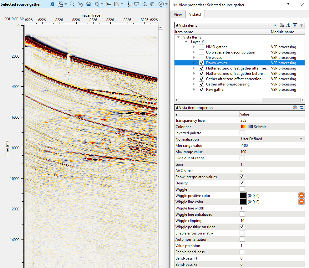
Now we can able to generate the CDP stack and velocity model. Prior to that we would like to show the down going/up going waves, NMO gathers etc. These can be found at the "Select source gather" display.
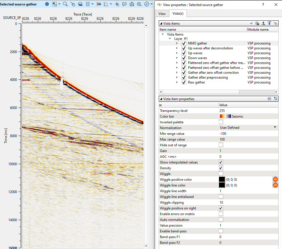
All these gathers are cascaded and we can able to see each of them by unchecking the gather one above. In above example, we see the NMO gather, when we uncheck the NMO gather, we can able to see the Up waves. Similarly the other gathers as well.
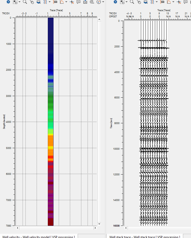
We can generate the zero offset stack (well stack ) and well velocity model from the first break picks. It calculates the slopes from the picked first break times and creates the depth interval velocity model (well velocity). To generate these outputs, we should check the Run zero offset processing option in the Select processes to run at the beginning of the Parameters section.
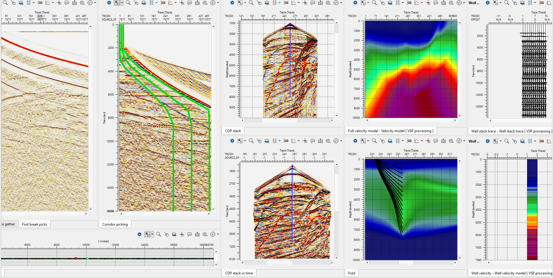
Zero offset processing generates the Well stack and Well velocity profile as shown below.
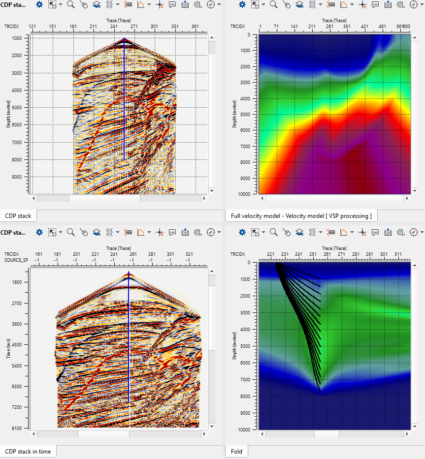
Now we are ready to execute our VSP Processing module to do the tomography updates to get the velocity model. For parametrization, please refer below in the parameters section. The final updated velocity, CDP stack and CDP stack in time displays are as shown below.
Parameters
Select Processes to run There are multiple processes to choose from and execute the VSP processing module to get the final results
Update selected source gathers By default, checked. This options updates the changes if the user made any like picking top and bottom mute and selected a different shot location on the location. Then the picked top and/or bottom mute picks will be automatically updated and showed on the new shot gather.
Run zero offset processing By default, checked. It will create the zero offset stack
Build full velocity model This will create the full and final velocity model upon execution of the VSP Processing module
Build full CDP stack It will create the final CDP stack both for time and depth.
General Provide the general parameters of the gather
V0(m/s) Specify the near surface/replacement velocity information
Shift to datum This option is unchecked by Default. Check if the user needs to shift the datum.
Datum(meter) Provide the datum value if the previous option is checked
KB (meter) Specify the Kelly Bush value.
First break auto picking
Window(ms) Define the first break picking window. We consider the time from 0 ms to the user defined value to scan and pick the first breaks. By default it is 5000 ms
Threshold Define threshold value
Pick positive phase Choose to pick the first breaks either on positive phase or negative phase. By default it is checked as positive phase.
Magnet type We have two options
Nearest We calculate the amplitudes in the up and down window of the sample we are looking for and divide the sum of amplitudes in the down window by sum of amplitudes in the up window to get the criteria to pick the first break.
Max Energy We calculate the energy in the up and down window of the sample we are looking for and divide the sum of energy in the down window by sum of energy in the up window to get the criteria to pick the first break.
Magnet window This parameter is useful when the user is editing the first breaks. The smaller the magnet window, the better it is. This will interpolate the first breaks between the already picked first breaks and the manual picks of that particular shot gather only.
NMO We are generating the NMO gather based on the first break picks. This calculates the total vertical time of the up and downgoing waves and add the first break time to get the total double vertical time.
stretch factor(%) Define the NMO stretch factor. By default 50%
Up/down separation
Separation method We can separate the up going and down going wavefields in two methods. They are "FK domain" and "Median filtering"
By default we have FK domain as the separation method.
Taper(%) This is the wave number (K) taper. Provide the taper value if the separation method is FK domain. By default it is 5%
Use FK filtering when no FB picks available This option activates when the user select the "Median filtering" as the choice of separation method. For Median filtering, we must have the "Use FK filtering when no FB picks available" option checked otherwise it will give an error message "Failed to find shot tree" when the user tries to go to a different shot gather. .
Filter window This option activates when the user selects the "Median filtering" as the choice of separation method. Provide the number of traces as the filter window. By default it is 10 traces. We are using the Median filter to attenuate the downgoing waves.
Deconvolution Provide the deconvolution parameters to apply deconvolution on upgoing waves.
Apply deconvolution to up-going waves By default unchecked. If checked, it will apply deconvolution to only on up-going waves.
Operator length(ms) Input deconvolution operator length
Lag time(ms) Provide the deconvolution gap length
Noise (%) Specify the white noise percentage added to the output
Convert wavelet to min phase By default unchecked. If the user wants to convert the wavelet to minimum phase, check this option.
Well stack trace It is the sum of all the zero offset traces within the corridor. This can be generated by choosing the option "Zero stack processing".
Number of shown traces Define number of traces should be displayed as "Well stack".
Velocity model We generate the zero offset velocity model (well velocity) once we pick all the first breaks and execute the VSP processing module. This velocity model refer to the Full velocity model in the vista items.
Velocity model grid step (meter) Grid step along the X,Y directions.
Additional aperture (meter) Adding additional aperture to avoid any edge effects to the velocity model.
Velocity model DZ (meter) Step size in the vertical direction (depth)
Correlation radius This radius uses to calculate the slope of a pilot trace. For an example, if we are defining the correlation radius as 5 that means we have to consider 5 traces on either side of the current trace. Now we calculate the slope of the current trace from the neighborhood first break pick times and use this value to calculate the velocity at the current trace receiver.
Velocity smooth radius (meter) To smooth the zero offset velocity model, define the smoothing radius.
Tomography We generate the velocity model based on the first break picks.
Number of global iterations Number of global iterations to update the velocity model.
Number of local iterations Number of local iterations to update the velocity model.
Frequency(Hz) Provide the dominant frequency value to consider in the velocity model updates.
Resolution(meter) Initial grid of the velocity model building. The bigger the resolution size the faster the tomo updates. On the downside, it will cost the resolution of the velocity model. It's user choice to go with the parameters.
Use velocity constrain Within the defined grid, we calculate the weighted averages of that particular cell depending on the number of rays passing through. This helps in updating the velocity model more accurately by means of number of rays passing through the cell. The more rays the better velocity update of that particular cell.
Velocity constrain window XY(meter) Velocity constrain grid size in X and Y directions.
Velocity constrain window Z(meter) Velocity constrain grid size in vertical(depth) direction.
Use velocity smooth By default it is checked as True.
Velocity smooth window XY(meter) Velocity smoothing window in X and Y directions
Velocity smooth window Z(meter) Velocity smoothing window in Vertical (Depth) direction.
Store time tables on disk If the user checks this option, it will store the travel time tables in the user specified directory.
Temporary storage path Provide the temporary storage path to store the travel time tables.
Threshold on update(%) By default value is 5% and works pretty good.
CDP stack When the velocity model is ready, we can able to generate the CDP stack. Here we generate the CDP stack in depth domain as well as time converted CDP stack.
Bin grid step X(meter) Radius of the bin size in X direction to combine the common depth points for that particular CDP
Bin grid step Y(meter) Radius of the bin size in Y direction to combine the common depth points for that particular CDP
Sample ratio(meter) Grid size in vertical (depth) direction.
Number of samples Total length
Aperture(meter) Maximum distance between the source and receivers.
Ray Casting To visualize the ray tracing.
Display rays By default it is checked as Yes.
Ray casting step(meter) Define the ray casting step.
Receiver decimation Provide the receiver decimation to visualize the rays on the display.