Edit velocity models: 2D and 3D (Time and Depth domains)
![]()
![]()
The module is designed to perform manual corrections to the velocity model. It allows for several types of adjustments to ensure the velocity model accurately represents the subsurface conditions. Key functionalities include smoothing of the velocity model to reduce abrupt changes and enhance continuity, as well as spike removal to eliminate unrealistic velocity anomalies and unwanted inversions. The module also supports interpolation in the velocity model where data may be edited by polygon or missing.
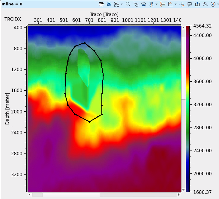
2D velocity model Before and After correction:

Additionally, the module offers the capability for replacing velocity values with constant values in specific regions, enabling users to enforce geological or physical constraints on the model. For more precise editing, the tool includes polygon-based surgical editing, which can be applied both on 2D vertical sections and 3D volume polygons. This allows for targeted adjustments to specific areas of the velocity model, ensuring high precision in the corrections. The module also provides the ability to work with 2D vertical sections and horizontal slices, facilitating localized corrections and visualizing the velocity model in different perspectives, in time and depth domains.
![]()
![]()
Input gather - input velocity model in gather format, 2D or 3D, time or depth format, load it to RAM (option in the Read seismic traces module).
![]()
![]()
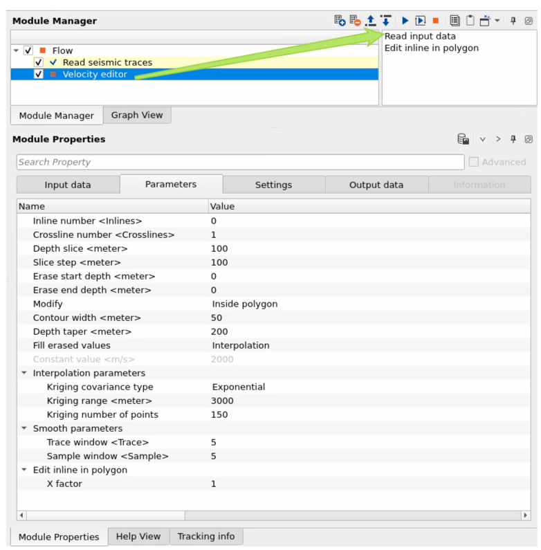
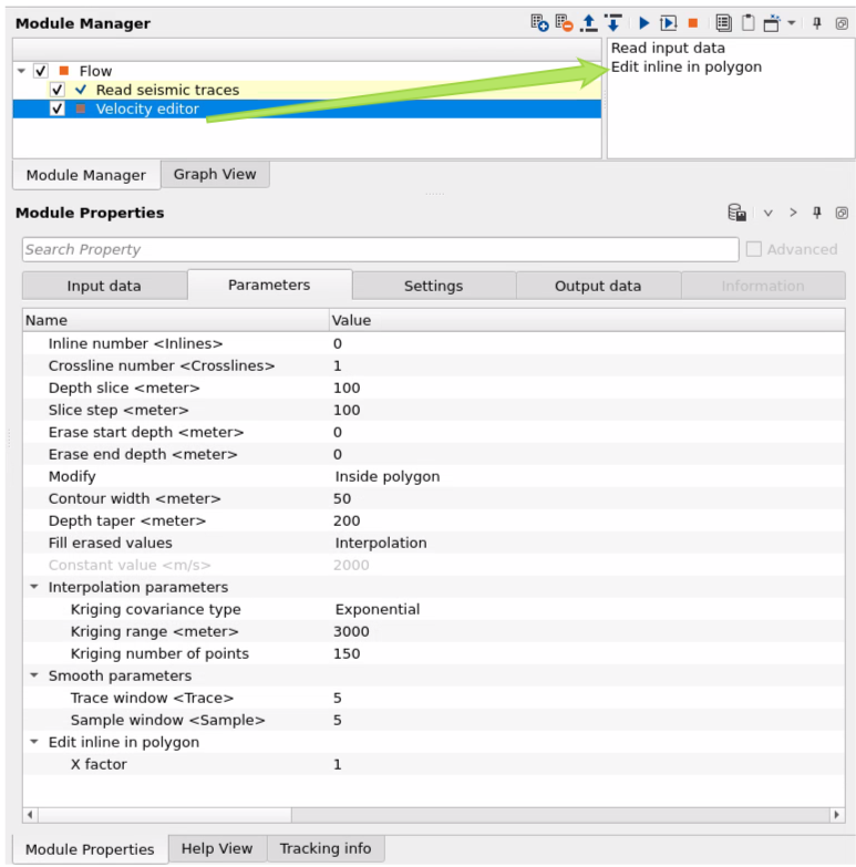
Inline number - define manually which inline section visualize in inline vertical section, or this number is defined automatically by selection on the Location map.
Crossline number - define manually which xline section visualize in inline vertical section, or this number is defined automatically by selection on the Location map.
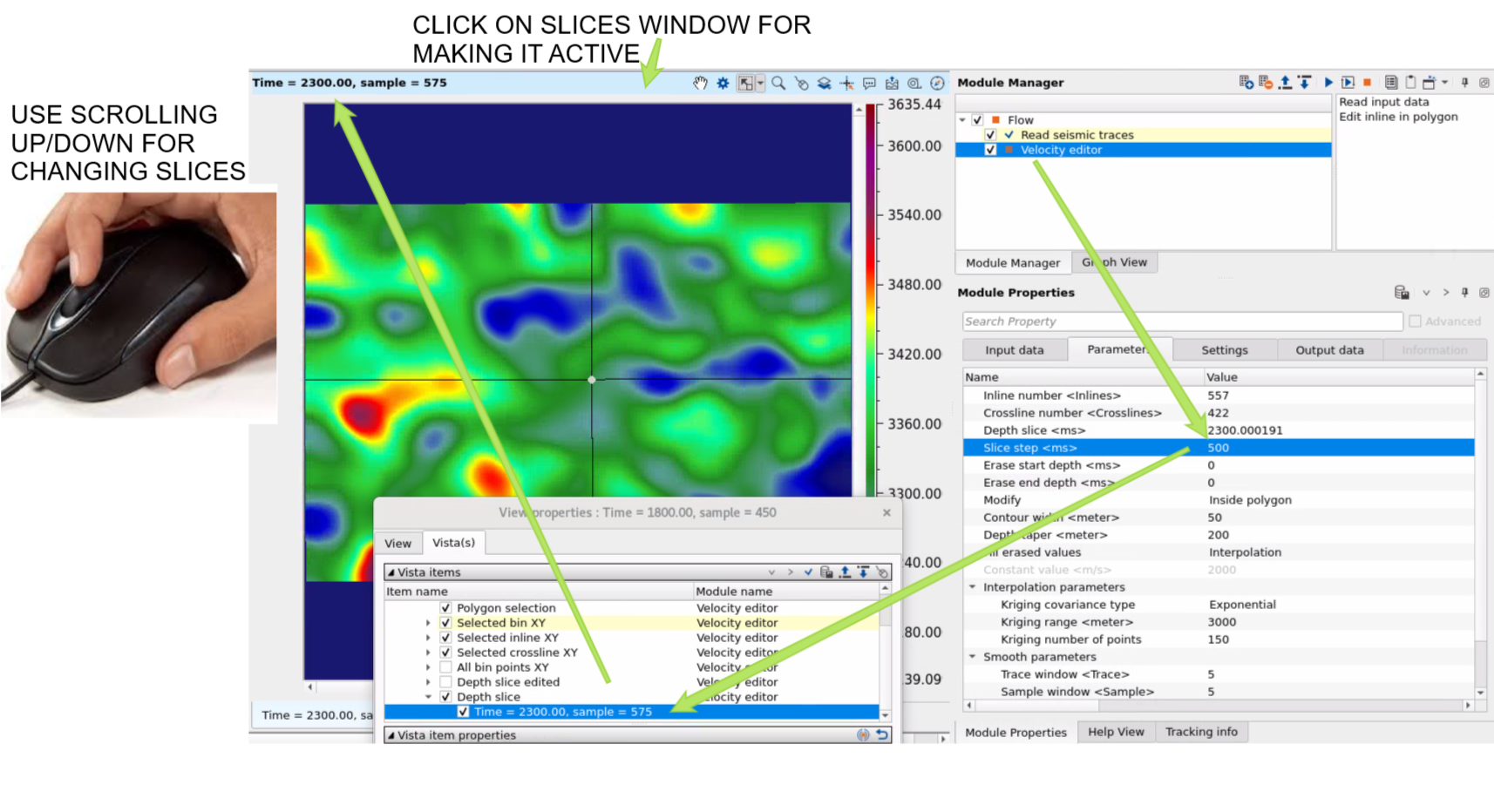
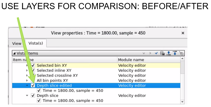
Depth slice - define manually which depth or time slice visualize on the slice section.
Slice step - define a step for slice that will b used when mouse scrolling is used on the slices window:
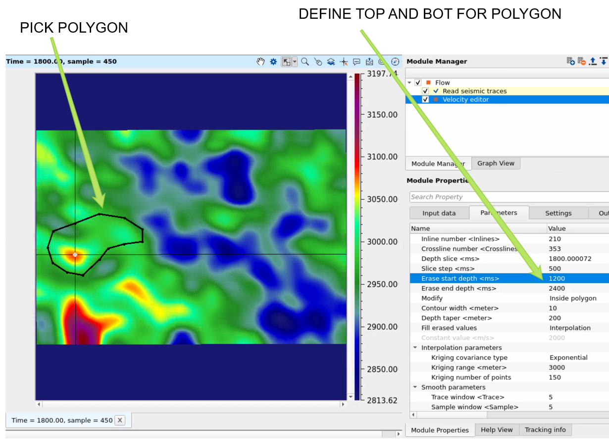
Erase start depth - for 3D polygon top limits.
Erase end depth - for 3D polygon bot limits.
Modify { Inside polygon, Outside polygon } - select option for editing: outside of the polygon or inside.
Contour width - width of contour
Depth taper - taper of merging zone between polygon and other part.
Fill erased values { Interpolation, Constant value } - select option or changing inside or outside polygon: interpolation or constant velocity value.
Constant value - define exact constant value of velocity (m/s) which will be inside or outside polygon .
Interpolation parameters:
Kriging covariance type { Exponential, Spherical, Gaussian } - choose the covariance type from the drop down menu:
Exponential - this can be used where the subsurface properties change abruptly over small distances.
Spherical - the Spherical model is useful when the data exhibits a more gradual spatial correlation up to a certain range and then behaves independently beyond that range. When subsurface structures have coherent properties within a certain distance but lose coherence at greater distances.
Gaussian - the Gaussian model is often applied in cases where there is a long-range, gradual spatial dependence between data points. It’s suitable for data where the spatial dependence does not drop off abruptly, such as when seismic properties gradually change over larger distances or in homogenous subsurface areas.
Kriging range - if two data points are closer than the kriging range, they are considered spatially correlated and will influence each other's estimated values. If the distance is greater than the range, their influence on each other will be ignored. If the distance between two data points is more than 500 then it assumes that the data beyond that limit there is no correlation.
Kriging number of points - total number of data points used to estimate/interpolate the unknown point/sample. The more the kriging points the better result however the computation time also increase with this.
Smooth parameters - determines the degree of smoothing applied to the velocity model. This parameter controls how much the velocity values are averaged or smoothed to reduce high-frequency variations or anomalies.
Trace window - defines the temporal or spatial range around each seismic trace used for interpolation. This parameter specifies the window of data points that will be considered when performing interpolation for each trace.
Sample window - specifies the range or number of samples considered for interpolation within a given window, allowing for control over the number of data points included in the interpolation process at each step.
Edit inline in polygon:
X factor - coefficient for making taper zone more consistent (equal), because of two different dimensions: traces (X) and time/depth (Y), so they have different values an we can not define accurate single taper value for both dimensions. Therefo use this factor for finding compromise for taper zone.
![]()
![]()
SegyReadParams - parameters for setting advanced parameters of reading seismic traces from disk:
Thread count (for SSD) - amount of treads for reading seismic traces from disk.
Bulk size (traces) - size of a chunk (data portion) for reading seismic traces from disk.
Execute on { CPU, GPU } - select which type of processor will be used for calculations: CPU or GPU.
Distributed execution - if enabled: calculation is on coalition server (distribution mode/parallel calculations).
Bulk size - chunk size is RAM in megabytes that is required for each machine on the server (find this information in the Information, also need to click on action menu button for getting this statistics):
Limit number of threads on nodes - limit numbers of of threads on nodes for performing calculations.
Job suffix - add an job suffix.
Set custom affinity - an axillary option to set user defined affinity if necessary.
Affinity - add your affinity to recognize you workflow in the server QC interface.
Number of threads - limit number of threads on main machine.
Run scripts - it is possible to use user's scripts for execution any additional commands before and after workflow execution:
Script before run - path to ssh file and its name that will be executed before workflow calculation. For example, it can be a script that switch on adn switch off remote server nodes (on Cloud).
Script after run- path to ssh file and its name that will be executed before workflow calculation.
Skip - switch-off this module (do not use in the workflow).
![]()
![]()
Output gather - output velocity gather.
Gather inline edited - output velocity gather.

There is no information.
![]()
![]()
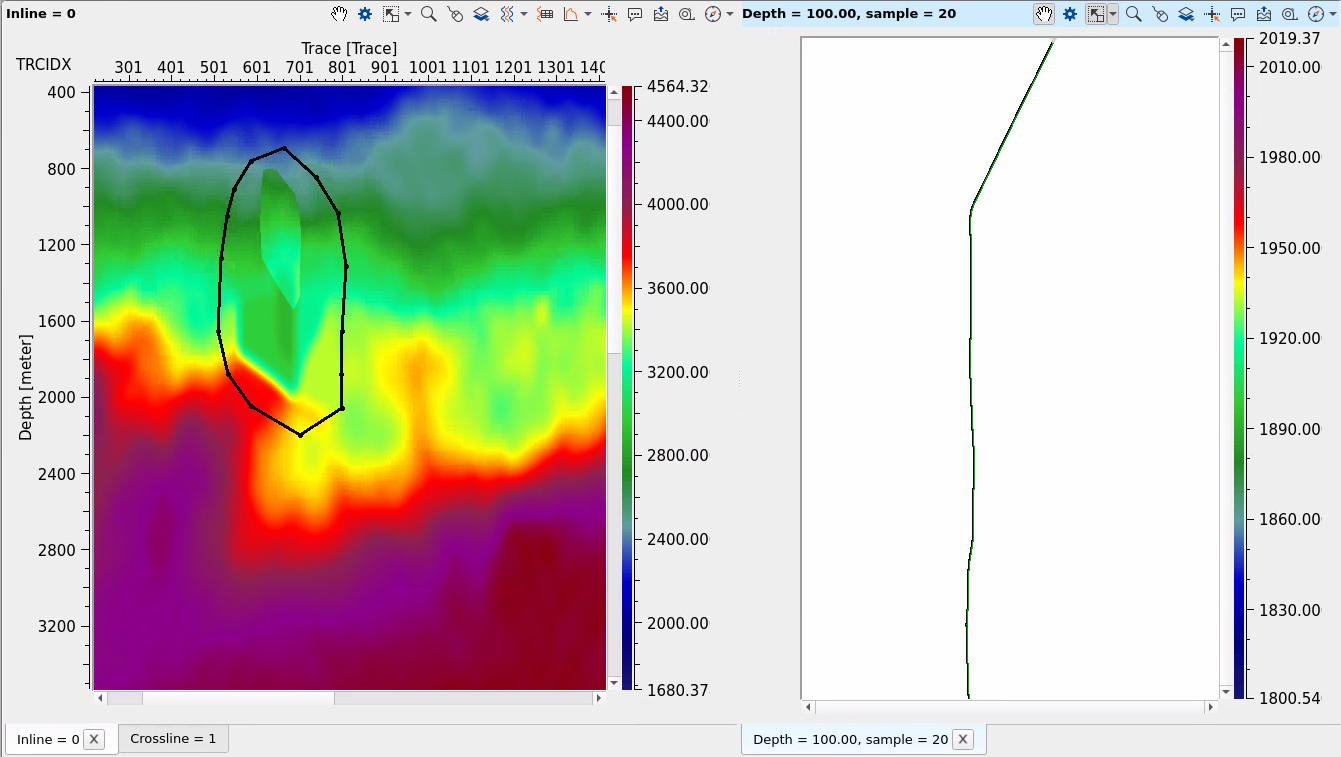
Read input data - initialization of input velocity, Use it for visualize all input data: Location map and vertical velocity sections.
Edit inline in polygon - open a menu for 2D section editing. Therefore use it only for 2D velocity, but for 3D use polygon on the location map (velocity slice layer) and execute module by double click on it (to edit velocity).
![]()
![]()
2D VELOCITY:
Press on Read input data in the action menu to visualize location map and vertical section of velocity filed:
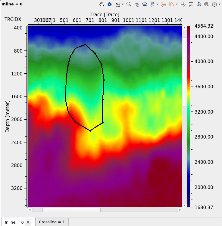
Create a polygon for velocity modification (can b inside or outside in accordance with parameters):
Click on Edit inline in polygon button in the action menu:
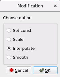
Select desired option for velocity modification:
The area inside polygon was modified:
3D VELOCITY:
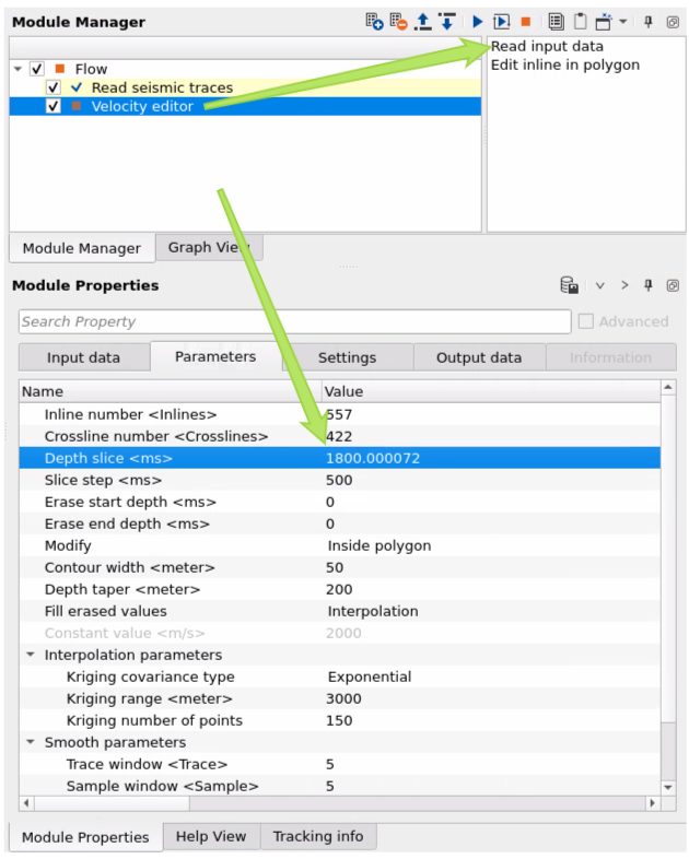
Press on Read input data in the action menu to visualize location map and vertical section of velocity filed, also we can define Depth slice parameter to go to the particular slice:
Select Polygon selection from the instrument panel of slice window:
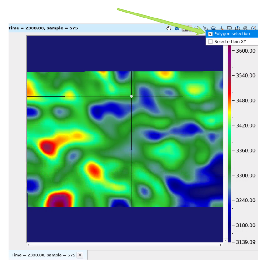
Create polygon via mouse drawing and define Erase start and Erase end parameters to making limits of top and bot. i.e. we have 3D version of polygon:
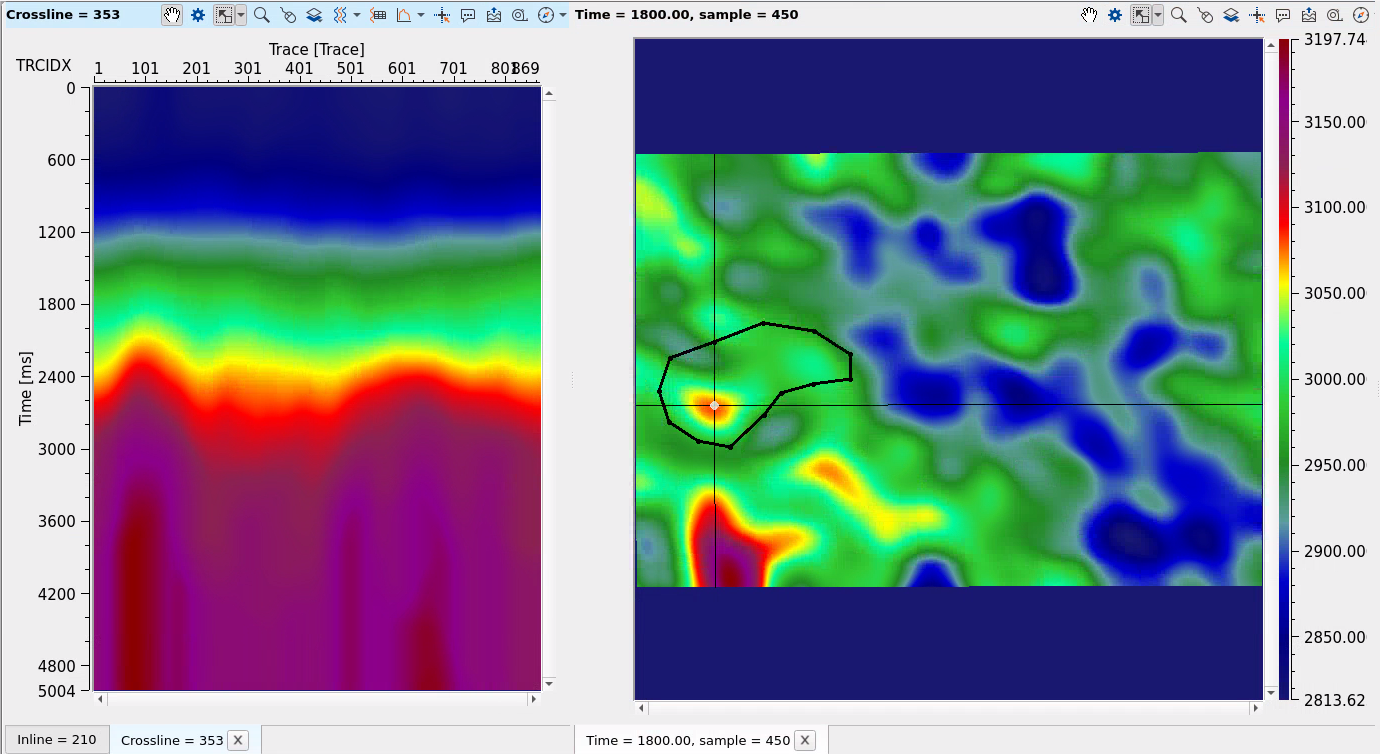
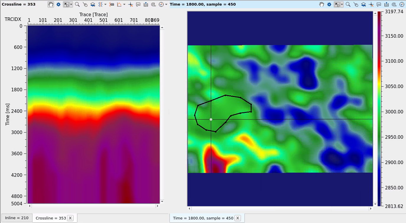
Execute the module and compare two results Before and After velocity modification:
BEFORE:
AFTER:
![]()
![]()
YouTube video lesson, click here to open [VIDEO IN PROCESS...]
![]()
![]()
 If you have any questions, please send an e-mail to: support@geomage.com