Surface Consistent Amplitude Correction Operators Calculation
![]()
![]()
SC Amplitude correction - Calculate is used to calculate operators for variations in amplitude that are caused by the seismic acquisition geometry, surface irregularities, and/or differences in source-receiver positions. This correction helps ensure that amplitude variations in seismic data are more consistent across the surface, making the data more uniform thus improving the reliability of subsequent interpretation steps. The correction also helps in improving the signal to noise ratio.
Different factors such as irregular surface, acquisition geometry parameters, distance between source and receiver (offset) contribute to the variation in amplitudes of the seismic data. To compensate the amplitudes, seismic data is decomposed into to time and frequency domains. Amplitudes are computed for each source-receiver pairs. SC Amplitude correction - calculate module calculates the operators for each source, receiver, cmp and offset iteratively. We calculate the scale factors/coefficients/operators for each trace and distribute equally to the each source, receiver, cmp and offsets respectively. The scale factors continue calculating for the particular trace until the parameters are stabilized (convergence). This is controlled by the threshold value where the difference between the successive iteration processes should be smaller and smaller as we proceed further.
After the operators are calculated, the operators are applied to the seismic data using the SC Amplitude correction – Apply module.
![]()
![]()
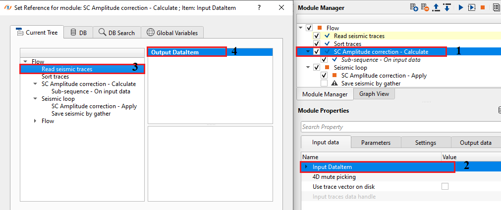
Input DataItem
Input SEG-Y data handle - connect/reference to the input data that went through all the denoise procedures and statics.
Input trace headers - connect/reference to the output trace headers of the input seismic gather.
4D mute picking - Mute is useful if there is any data above the first arrivals. It is necessary to remove any noise the first breaks. Provide the input mute picks file if necessary.
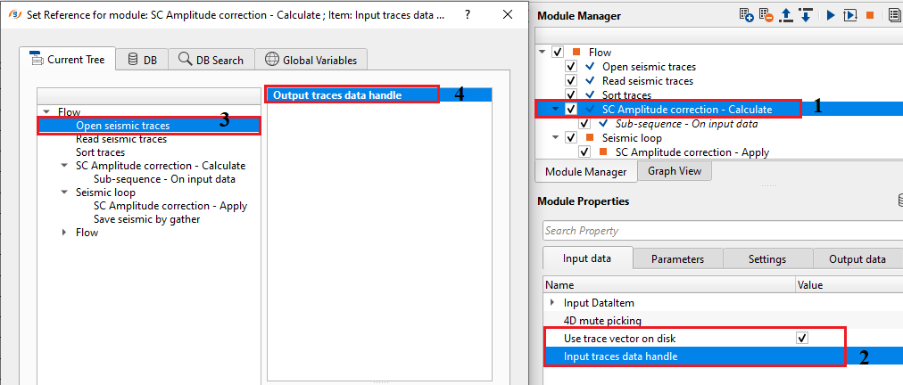
Use trace vector on disk - this option is used when the input data size is big. Use this option in case trace header data (vector) is large for uploading it to the RAM. Therefore all trace headers will be uploaded directly from the disk without using necessity of RAM. By default, FALSE. If checked, the user should provide the Input traces data handle.
Input traces data handle - connect/reference to the Output traces data handle of the Open seismic traces module. This option isn't available for "Read seismic traces" or "Read SEG-Y traces" modules.
![]()
![]()
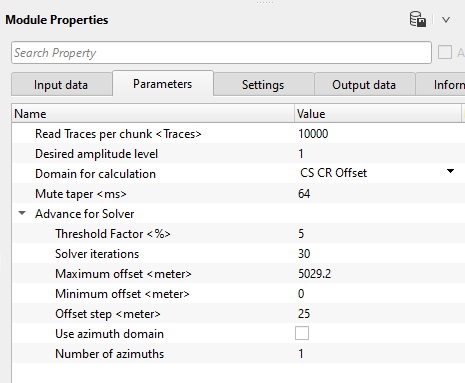
Read Traces per chunk - Number of traces to read in for the calculation.
Desired amplitude level - Set the desired amplitude level. By default, 1.
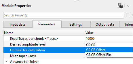
Domain for calculation { CS CR, CS CR Offset, CS CR Offset Bin } - Surface Consistent Amplitude correction (SCAMP) will be performed in 3 different domains. There are many reasons to perform/calculate the SCAMP in different domains.
Common Source domain takes care of the distortions created by the source wavelet or seismic source like dynamite/vibroseis/air gun.
Common Receiver domain will look into the distortions recorded at the receives due to receiver sensitivity and noise levels recorded.
Common Offset domain handles all the amplitude variations caused by the offsets.
Common Bin takes care of any distortions spatially.
Mute taper - It is used to avoid any sharp boundaries. This option is required when the user used the input mute file.
Advance for Solver - This section deals with the solver parameters. SC Amplitude correction - calculate module calculates the operators for each source, receiver, cmp and offset iteratively. We calculate the scale factors/coefficients/operators for each trace and distribute equally to the each source, receiver, cmp and offsets respectively. The scale factors continue calculating for the particular trace until the parameters are stabilized (convergence). This is controlled by the threshold value where the difference between the successive iteration processes should be smaller and smaller as we proceed further.
Threshold Factor - specify the threshold value that should be considered for stopping the iteration process where the successive iteration values reaches the user defined threshold factor/value.
Solver iterations - specify total number of iterations to be performed for calculation.
Maximum offset - specify the maximum offset to be considered in the calculation.
Minimum offset - specify the minimum offset to be considered in the calculation.
Offset step - specify the offset step size.
Use azimuth domain - In case the seismic distortions are caused due to azimuths (distortions due to the directional variations). By default, FALSE. If checked, the user has to be provide the number of azimuths to be considered in the calculation.
Number of azimuths - specify the number of azimuths considered for the calculation.
![]()
![]()
Auto-connection - By default, TRUE(Checked).It will automatically connects to the next module. To avoid auto-connect, the user should uncheck this option.
Execute on { CPU, GPU } - select which type of processor will be used for calculations: CPU or GPU.
Distributed execution - if enabled: calculation is on coalition server (distribution mode/parallel calculations).
Bulk size - chunk size is RAM in megabytes that is required for each machine on the server (find this information in the Information, also need to click on action menu button for getting this statistics):
Limit number of threads on nodes - limit numbers of of threads on nodes for performing calculations.
Job suffix - add a job suffix.
Set custom affinity - an auxiliary option to set user defined affinity if necessary.
Affinity - add your affinity to recognize you workflow in the server QC interface.
Number of threads - One less than total no of nodes/threads to execute a job in multi-thread mode. Limit number of threads on main machine.
Run scripts - it is possible to use user's scripts for execution any additional commands before and after workflow execution.
Script before run - path to ssh file and its name that will be executed before workflow calculation. For example, it can be a script that switch on and switch off remote server nodes (on Cloud).
Script after run - path to ssh file and its name that will be executed before workflow calculation.
Skip - By default, FALSE(Unchecked). This option helps to bypass the module from the workflow.
![]()
![]()
Output DataItem - Generates the Output data item with all the trace headers information.
Average amplitude level - Outputs the average amplitude level value.
Output gather CS - Output common shot gather after SC Amplitude correction.
Output gather CR - Output common receiver gather after SC Amplitude correction.
Input gather CS - Input common shot gather before SC Amplitude correction.
Input gather CR - Input common shot gather before SC Amplitude correction.
AmplitudeRecoveryDataItem - Outputs the amplitude recovery spectrum as an item.
Number of sources - total number of sources.
Number of receivers - total number of receivers.
Number of bins - total number of bins/cmp.
![]()
![]()
In this example workflow, we are reading the input gathers using Read seismic traces. In case the input data size is too big then it is advisable to use "Use trace vector on disk" option to read the data. When using this option, the user must read the data using "Open seismic traces" module only.
Adjust the parameters as per the data requirement and execute the job either standalone or using nodes.
SC Amplitude correction - Calculate module generates the convergence, source and receiver amplitude correction maps as Vista items.
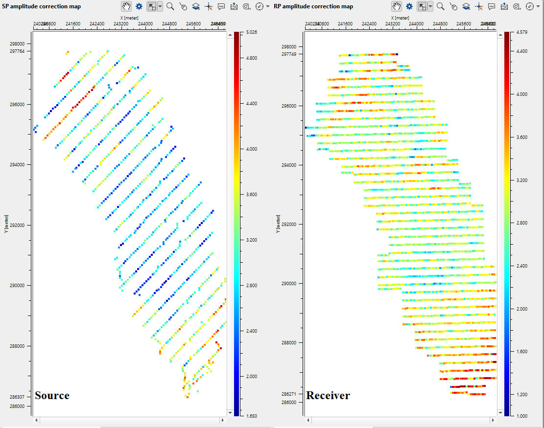
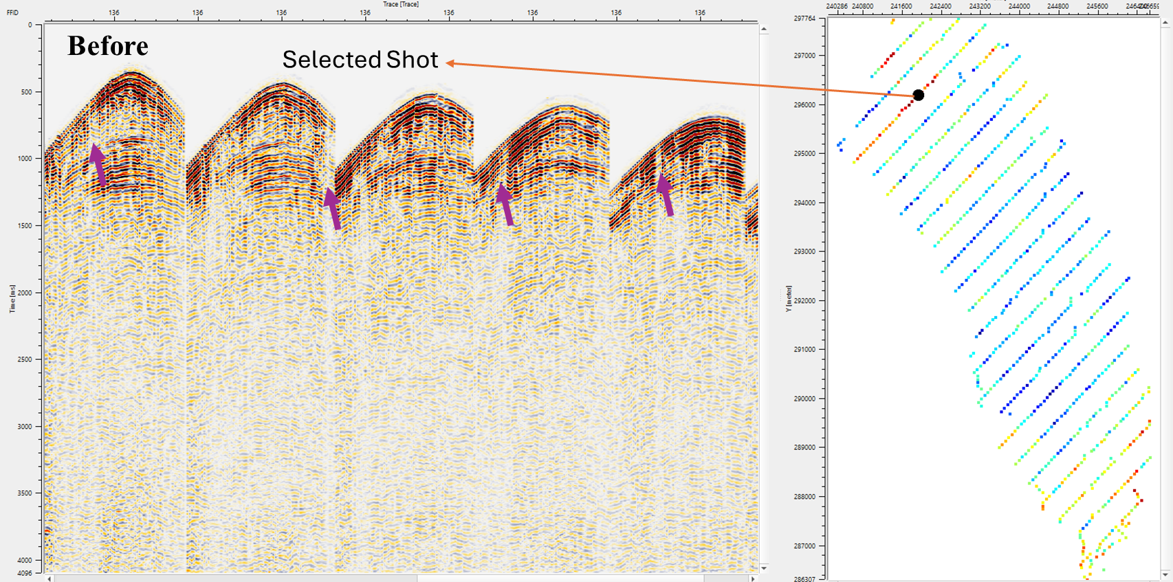
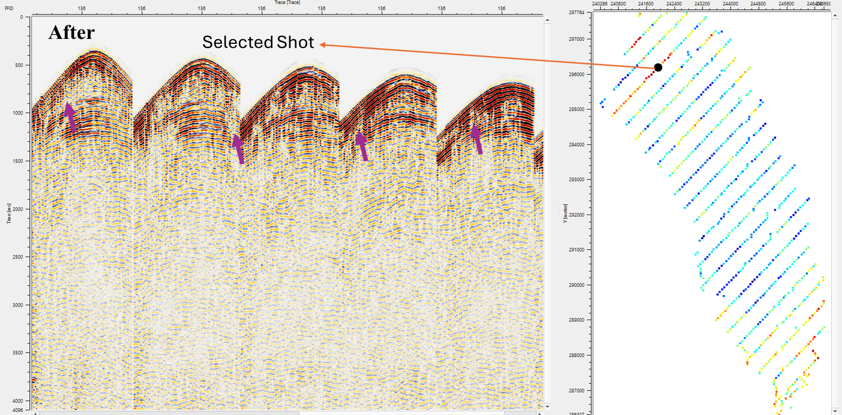
Within this module, the user can quickly QC the amplitude corrections by selecting the respective shot and receiver gathers from the source and receiver amplitude correction map. It will display the gathers with and without amplitude corrections. In the below images, we are showing a shot gather before and after amplitude correction. The arrow marks displaying the shot gather with changes in the amplitudes.
![]()
![]()
There are no action items available for this module so the user can ignore it.
![]()
![]()
YouTube video lesson, click here to open [VIDEO IN PROCESS...]
![]()
![]()
Yilmaz. O., 1987, Seismic data processing: Society of Exploration Geophysicist
 * * * If you have any questions, please send an e-mail to: support@geomage.com * * *
![]()