Calculating Surface Consistent Deconvolution
![]()
![]()
What is Surface Consistent? A Single Operator calculated for all traces that have the same surface point location in common. Why do we perform surface consistent? During the seismic acquisition survey design phase we design the survey parameters for a normal situation however when we acquire the data in different terrains the conditions will be quite different. Due to sub-surface nature, the data is recorded with many distortions due to various reasons like the survey design, acquisition instruments or the sub-surface change in properties.
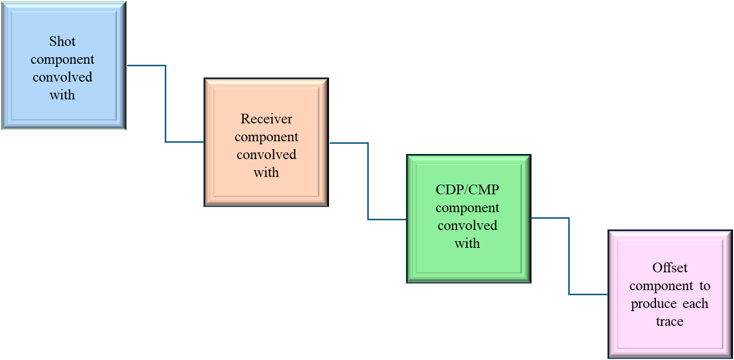
Surface consistent deconvolution assumes that a seismic trace consists of the convolution of a number of components which go together to produce the seismic trace. For example, each shot, each receiver position, each CDP and each trace offset (or channel number) contributes its own spectral modification to the seismic trace.
Surface consistent deconvolution attempts to reverse this process by extracting the original log spectra (for each shot, each receiver) from all of the original input data. This is done by averaging the log spectra for each shot, each receiver, each CDP and each offset (Channel) and then using a Gauss-Seidel iterative technique to isolate the individual components. Using the Gauss-Seidel method, it computes the deconvolution filters for each frequency band to improve the resolution of the seismic wavelet.
![]()
![]()
Input DataItem
Input SEG-Y data handle - connect/reference to the input data that went through all the denoise procedures and statics.
Input trace headers - connect/reference to the output trace headers of the input seismic gather.
4D mute picking - Mute is useful if there is any data above the first arrivals. It is necessary to remove any noise the first breaks. Provide the input mute picks file if necessary.
Use trace vector on disk - This option is used when the input data size is big. By default, FALSE. If checked, the user should provide the Input traces data handle.
Input traces data handle - connect/reference to the Output traces data handle of the Open seismic traces module. This option isn't available for "Read seismic traces" or "Read SEG-Y traces" modules.
![]() Fast solving & Gauss-Seidel TVOD size parameters are only applicable when we the user uses the option "Use trace vector on disk".
Fast solving & Gauss-Seidel TVOD size parameters are only applicable when we the user uses the option "Use trace vector on disk".
![]()
![]()
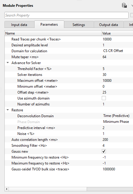
Read Traces per chunk - Number of traces to read in for the calculation
Desired amplitude level - Set the desired amplitude level. By default, 1.
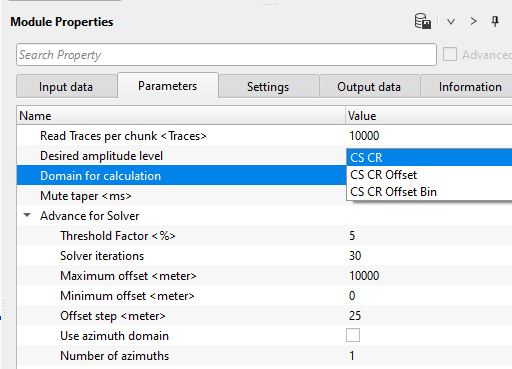
Domain for calculation { CS CR, CS CR Offset, CS CR Offset Bin } - Surface Consistent Deconvolution (SCDCN) will be performed in 3 different domains. There are many reasons to perform/calculate the SCDCN in different domains.
Common Source domain takes care of the distortions created by the source wavelet or seismic source like dynamite/vibroseis/air gun.
Common Receiver domain will look into the distortions recorded at the receives due to receiver sensitivity and noise levels recorded.
Common Offset domain handles all the amplitude variations caused by the offsets.
Common Bin takes care of any distortions spatially.
Mute taper - It is used to avoid any sharp boundaries. This option is required when the user used the input mute file.
Advance for Solver - This section deals with the solver parameters. For solving, we use Gauss-Seidel method to resolve all the distortions of the seismic wavelet and improves the spatial and temporal resolution of the seismic wavelet in an iterative method. We do the iteration until the parameters are stabilized (convergence). This is controlled by the threshold value where the difference between the successive iteration processes should be smaller and smaller as we proceed further.
Threshold Factor - specify the threshold value that should be considered for stopping the iteration process where the successive iteration values reaches the user defined threshold factor/value.
Solver iterations - specify total number of iterations to be performed for calculation.
Maximum offset - specify the maximum offset to be considered.
Minimum offset - specify the minimum offset to be considered.
Offset step - specify the offset step size
Use azimuth domain - In case the seismic distortions are caused due to azimuths (distortions due to the directional variations). By default, FALSE. If checked, the user has to be provide the number of azimuths to be considered in the calculation.
Number of azimuths - specify the number of azimuths considered for the calculation.
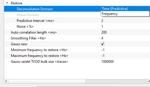
Restore - This sections deals with the restoration of the seismic reflection energy by performing the deconvolution in time or frequency domain.
Deconvolution Domain { Time (Predictive), Frequency } - choose the preferred domain from the drop down menu to perform the deconvolution. By default, Time (Predictive).
DeconvolDomain - Frequency - In case the deconvolution domain is frequency, the deconvolution calculation happens in the frequency domain where the data is transformed from time domain to frequency domain by using Fourier transform. In that case, the user needs to provide the phase domain parameters.
Phase Domain { Minimum Phase, Zero Phase } - Naturally, Deconvolution expects the data in minimum phase where it is easier to distinguish between the signal and noise (seismic energy is concentrated at the very beginning) unlike the zero phase wavelet where the energy is distributed symmetrically with a slight delay of time.
DeconvolDomain - Time (Predictive) - Deconvolution will be performed in time domain.
Predictive interval - specify the predictive interval value
Noise - specify the percentage white noise added to the deconvolution process to stabilizes the result.
Auto correlation length - specify the auto-correlation length. This helps in better parametrization of the deconvolution.
Smoothing Filter - smoothing filter value is used to smoothing of the spectra.
Fast solving - By default, TRUE (Checked). This will helps in solving the Gauss-Seidel method much faster. This parameter is applicable only when the user reads the data from "Open seismic traces" ONLY.
Minimum frequency to restore - specify the minimum frequency to be restored. By default, -1 which means all frequencies.
Maximum frequency to restore - specify the maximum frequency to be restored. By default, -1 which means all frequencies.
Gauss-seidel TVOD bulk size - Default value is good to start with. This is valid when the Fast solving option is checked.
![]()
![]()
Auto-connection - By default, TRUE(Checked).It will automatically connects to the next module. To avoid auto-connect, the user should uncheck this option.
Execute on { CPU, GPU } - select which type of processor will be used for calculations: CPU or GPU.
Distributed execution - if enabled: calculation is on coalition server (distribution mode/parallel calculations).
Bulk size - chunk size is RAM in megabytes that is required for each machine on the server (find this information in the Information, also need to click on action menu button for getting this statistics):
Limit number of threads on nodes - limit numbers of of threads on nodes for performing calculations.
Job suffix - add a job suffix.
Set custom affinity -
SetCustomAffinity - true - an axillary option to set user defined affinity if necessary.
Affinity - add your affinity to recognize you workflow in the server QC interface.
Number of threads - limit number of threads on main machine.
Run scripts - it is possible to use user's scripts for execution any additional commands before and after workflow execution:
Script before run - path to ssh file and its name that will be executed before workflow calculation. For example, it can be a script that switch on and switch off remote server nodes (on Cloud).
Script after run - path to ssh file and its name that will be executed before workflow calculation.
Skip - By default, FALSE(Unchecked). This option helps to bypass the module from the workflow.
![]()
![]()
Output DataItem - Generates the Output data item with all the trace headers information.
Average amplitude level - Outputs the average amplitude level
Output gather CS - Output common shot gather after SC Deconvolution
Output gather CR - Output common receiver gather after SC Deconvolution
Input gather CS - Input common shot gather before SC Deconvolution
Input gather CR - Input common receiver gather before SC Deconvolution
FrequencyResponseSpectrumItem - Outputs the frequency response spectrum as an item.
Number of sources - total number of sources
Number of receivers - total number of receivers
Number of bins - total number of bins
Number of frequencies - total number of frequency bands
Frequencies step - frequency step size
![]()
![]()
In this example workflow, we are reading an input data set which had undergone denoise and statics procedures.
Connect/reference the Input Dataitem to Output Dataitem of "Read seismic traces"
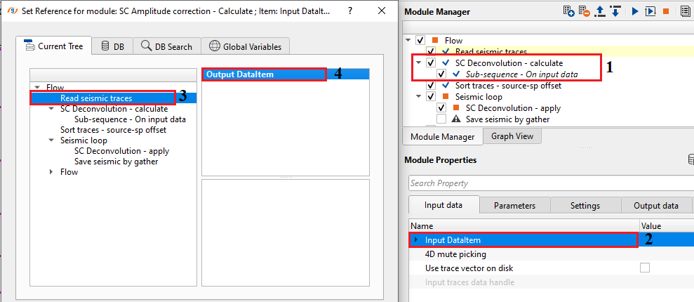
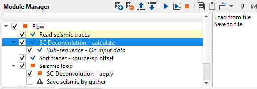
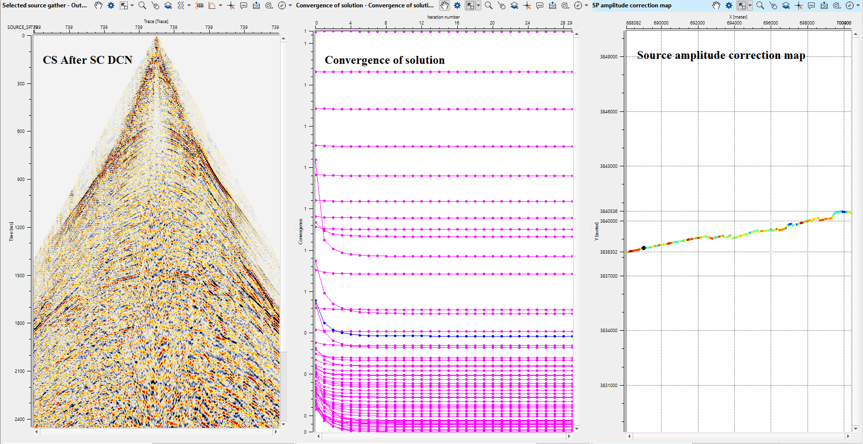
Execute the workflow and generate the vista items. We'll see the common shot and common receiver gathers before and after application of the SC deconvolution, convergence of solver for each frequency band, source and receiver amplitude map for each frequency band.
![]()
![]()
Load from file - This action item allows the user to load the previously saved SC deconvolution calculation file ".scdecon".
Save to file - This action item allows the user to save the calculated surface consistent deconvolution values into a file. Click on this option and new pop-up window opens. Provide the file name and click Save. It will save the file with an extension of ".scdecon".
![]()
![]()
YouTube video lesson, click here to open [VIDEO IN PROCESS...]
![]()
![]()
Yilmaz. O., 1987, Seismic data processing: Society of Exploration Geophysicist
 * * * If you have any questions, please send an e-mail to: support@geomage.com * * *