Convert vibroseis data
Converting uncorrelated vibroseis data into correlated seismic data
Theory
Cross-correlation is a measure of the similarity between two series f(t) and g(t) as a function of the displacement (lag) of one relative to the other.
Consider two real functions f(t) and g(t) that differ only by an unknown shift along the time (X) axis. By computing the cross-correlation, we can determine how much g(t) must be shifted to best align with f(t). The cross-correlation formula effectively slides g(t) along the axis and computes the integral of their product at each shift.
When the functions match, the value of (f * g) is maximized. This occurs because:
- When peaks align, their product contributes a large positive value.
- When troughs align, the product of two negative values is still positive, also contributing to a large correlation value.
The cross-correlation of f(t) and g(t) is equivalent to the convolution of f*(-t) with g(t) : (f * g) (t) = f* (-t) * g(t)
where f* denotes the complex conjugate of f.
Vibroseis Data Conversion:
Vibroseis source is a long train of sine waves of increasing or decreasing frequencies. Conventional impulsive source like dynamite produces a single discrete impulse for each event, whereas the Vibroseis source will show the event as a pulse train. In an uncorrelated seismic record, the pulse trains for each event overlap and cannot be separated by the human eye. However, after cross-correlation with the input sweep, each event should appear as a synthetic pulse which has the shape of the auto-correlation of the sweep.
Following are the advantages …
- Since we know the form of the source signal, we can easily remove the back ground noise from the data using the source signal
- We know the Vibroseis sweep frequency band, anything outside the frequency band limit of the sweep can be considered as a noise and that can be filtered out.
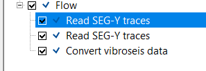
Figure 1. Schematic diagram of Vibroseis data Cross Correlation and Deconvolution (Image courtesy: SEG Wiki)
Why This Method is Used
- Vibroseis sweeps are long and non-impulsive. Correlation converts them into short wavelets
- Klauder wavelet is predictable and invertible. It enables stable deconvolution
- Produces clean seismic data with increased temporal resolution
- Works reliably on land and desert Vibroseis datasets
User recommendations:
In the Output data tab, users can save the Klauder Wavelet, Min Phase Decon Operator, Modeled Sweep Signal etc.
In the Output data tab, users can save the Klauder Wavelet, Min Phase Decon Operator, Modeled Sweep Signal etc.
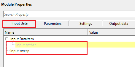
Input data
Input DataItem
Input gather
connect/reference to Output gather that needs to be converted.
Input sweep
provide the vibroseis sweep signal as an input.
Parameters
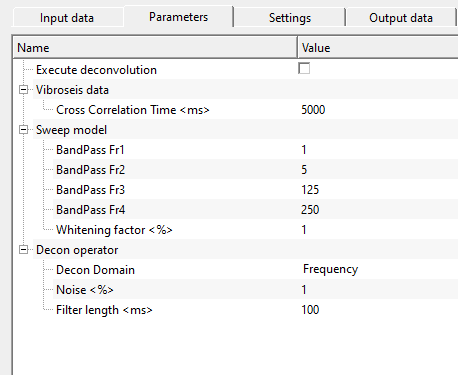
Execute deconvolution
this allows the user to perform deconvolution on the input data. By default, FALSE (Unchecked). Vibroseis data has broader side lobes, poor vertical (temporal) resolution. Deconvolution helps in removing the side lobes and increases the vertical resolution.
Vibroseis data
this section deals with the input vibroseis data. User should choose the parameters.
Cross Correlation Time
input field gather is cross-correlated by sliding the sweep across the input data. This removes the sweep from the input data and provides us normal seismic gather. Cross correlation time is used to determine how much time is required to match the sweep with the input data to remove the sweep from the recorded field data.
Sweep model
this section deals with the input field sweep. In order to match with the input data frequency band, we filter the input sweep with the following filter parameters. It gives a clean Klauder wavelet by performing the auto-correlation.
BandPass Fr1
provide the lower frequency taper/slope
BandPass Fr2
provide the low frequency to pass through
BandPass Fr3
provide the high frequency to pass through
BandPass Fr4
provide the high frequency taper/slope
Whitening factor
this stabilizes the output wavelet and increases the higher frequency.
Decon operator
this section deals with deconvolution. As we mentioned earlier, Deconvolution helps to get a cleaner sharp wavelet with better vertical resolution.
Decon Domain { Frequency, Time }
select the deconvolution domain. By default, Frequency.
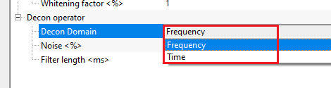
In time domain, it creates the deconvolution operator by using the auto-correlation and prediction error filter. Whereas in the Frequency domain, it uses the amplitude and phase spectra of Klauder wavelet.
Noise
add percentage while noise to the deconvolution operator to stabilize the output.
Filter length
specify the length of the deconvolution operator. It controls the duration of the wavelet to be removed.
Settings
Auto-connection
By default, TRUE(Checked).It will automatically connects to the next module. To avoid auto-connect, the user should uncheck this option.
Bad data values option { Fix, Notify, Continue }
This is applicable whenever there is a bad value or NaN (Not a Number) in the data. By default, Notify. While testing, it is good to opt as Notify option. Once we understand the root cause of it, the user can either choose the option Fix or Continue. In this way, the job won't stop/fail during the production.
Notify
It will notify the issue if there are any bad values or NaN. This will halt the workflow execution.
Fix
It will fix the bad values and continue executing the workflow.
Continue
This option will continue the execution of the workflow however if there are any bad values or NaN, it won't fix it.
Skip
By default, FALSE(Unchecked). This option helps to bypass the module from the workflow.
Output data
Output DataItem
Output gather
generates output gather
Output Vibs Decon filter
generates deconvolution filter operator as an output
This output contains the shaping filter that converts the autocorrelation of the sweep signal into a desired target wavelet. The filter is computed by solving a Wiener-Levinson system using the autocorrelation of the sweep and the cross-correlation between the sweep and the minimum-phase equivalent wavelet. Save this item to inspect the deconvolution operator or to use it for quality control. Connect it to a display module to verify that the operator is well-behaved (compact, causal, and free of ringing). This output is only meaningful when the Execute deconvolution option is enabled.
Min Phase Wavelet
generates minimum phase wavelet
This output contains the minimum-phase equivalent of the correlated sweep (Klauder wavelet). It is derived from the amplitude spectrum of the autocorrelated sweep signal by converting the mixed-phase Klauder wavelet into its minimum-phase counterpart using a cepstral technique. Save and inspect this wavelet to verify that the bandpass filter boundaries and whitening factor are producing a compact, well-shaped wavelet before proceeding with deconvolution. A clean, spike-like minimum-phase wavelet indicates that the conversion parameters are set correctly.
Sweep
generates sweep as an output
This output provides the modeled pilot sweep signal used as the reference for cross-correlation. When an Input sweep gather is connected, that recorded pilot sweep is used; otherwise the first trace of the input gather is treated as the sweep reference. Save and visualize this item to confirm that the correct sweep signal is being used for the correlation. A typical linear vibroseis sweep will appear as a sinusoidal signal with linearly increasing frequency.
Sweep Ato correaltion
generates auto-correlated sweep as an output.
This output contains the autocorrelation of the sweep signal, which is the theoretical Klauder wavelet. The Klauder wavelet is the zero-phase wavelet that results from correlating the vibroseis sweep with itself, and it defines the wavelet shape present in the correlated seismic data. The length of this autocorrelation trace is controlled by the Cross Correlation Time parameter. Save and inspect this output to understand the expected wavelet character of your correlated data before running deconvolution.
Information
This module runs as a standard sequential processing step and does not expose GPU acceleration or distributed execution options. No additional settings are required beyond the parameters configured in the Parameters tab. The module processes each input gather trace-by-trace in the frequency domain, applying cross-correlation and optional deconvolution, and produces the correlated output gather along with the diagnostic output wavelets.
Examples
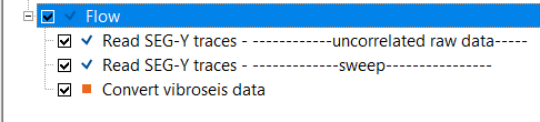
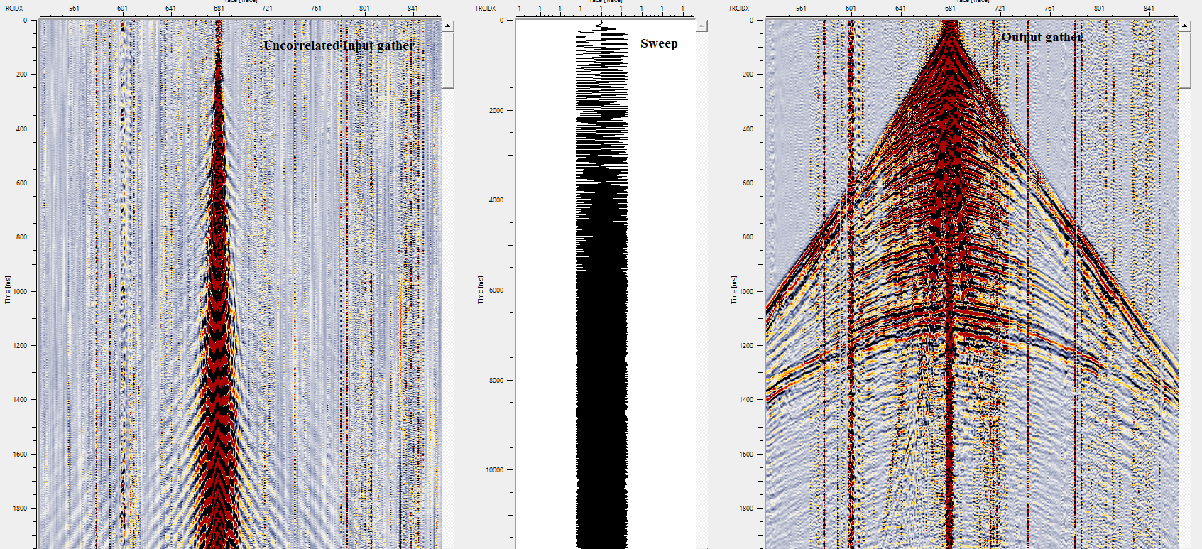
In this example workflow, we are reading two input dataset(s). One is uncorrelated raw seismic data and the second one is vibroseis sweep. Both the inputs are in SEG-Y format. So, we are reading the input dataset(s) by using Read SEG-Y traces.Also, Load data to RAM as YES.
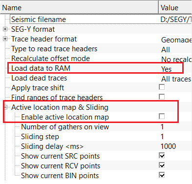
For this particular exercise, we are reading a single shot gather so we are using Load data to RAM as YES. In case of full line, the user can use "Enable Active location map" inside the Active location map & sliding section.
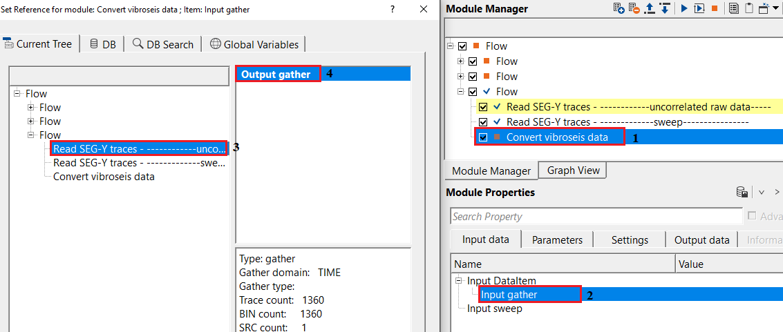
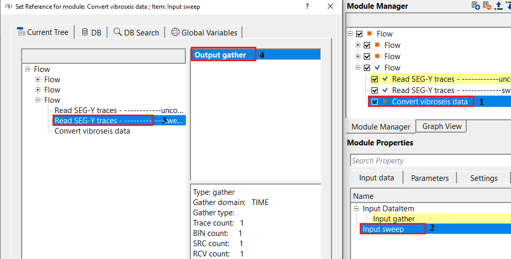
Make the necessary connections as per the input data requirements.
Adjust the parameters as per the input data. There are few parameters are not required. The important parameter should be the "Cross correlation time". Adjust the parameter and execute the module. It will provide Input & Output gather.
Actions
There are no action items available for this module so the user can ignore it.
Video lesson
YouTube video lesson, click here to open [VIDEO IN PROCESS...]
Related articles
Yilmaz. O., 1987, Seismic data processing: Society of Exploration Geophysicist
 * * * If you have any questions, please send an e-mail to: support@geomage.com * * *
References
Crawford, J. M., Doty, W. E. N., and Lee, M. R., 1960, Continuous signal seismograph: Geophysics, 25, 95-105.