In g-Platform there are two ways how to build a stack. First, the system includes a special interactive tool (module) Stack imaging which does have all necessary functionality for stack creation: velocity analyze, mute function definition, stack creation, datum planes options and so on. Second, it is an conventional way for stack creation where we should create a workflow of several modules like NMO applying, mute function, stacking. We will discuss the most convenient option is using Stack imaging:
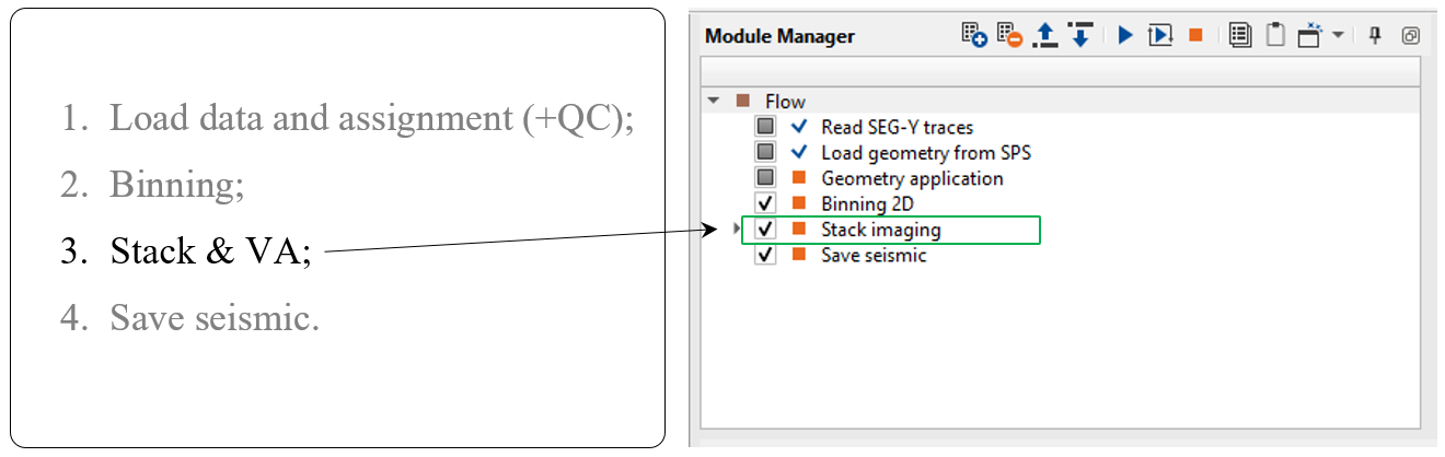
Stack imaging
This module is complex interactive application for velocity analysis, creating mute function, stacking CMP gathers, but we don't need to use all these option in this chapter. This step is only for QC, so we just need to build two stacks and compare them: before and after spherical divergence correction. Pay attention on what is inside Stack imaging module, it is sub-sequence. Sub-sequence helps to avoid creating a separate workflow to apply an AGC or Deconvolution or other processing modules, we just simply insert those modules in the sub-sequence inside the main module.
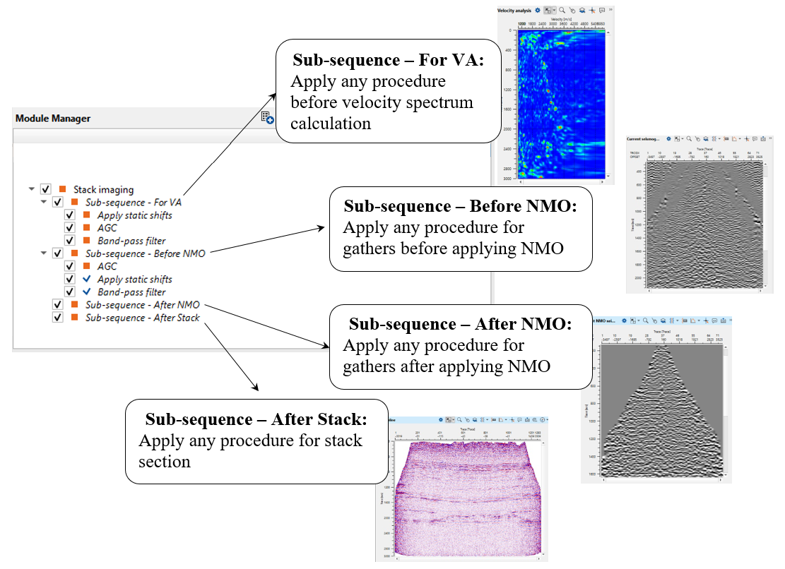
There are four sub-sequences inside Stack imaging:
•Sub-sequence - For VA: processing for velocity analysis, i.e. apply some procedures like band-pass or AGC, and then velocity spectrum is calculated;
•Sub-sequence - Before NMO: processing before applying NMO corrections to gathers, for example we can apply static corrections;
•Sub-sequence - After NMO: processing before applying NMO corrections to gathers, for example we can apply denoise procedures;
•Sub-sequence - After Stack: processing after stacking CMP gathers, for example we can apply denoise procedures or spectrum balancing.
Use action menu of Stack imaging module: there are many options, for example we can save and import stacking velocity or mute function, calculate and save on a disk the entire stack cube:
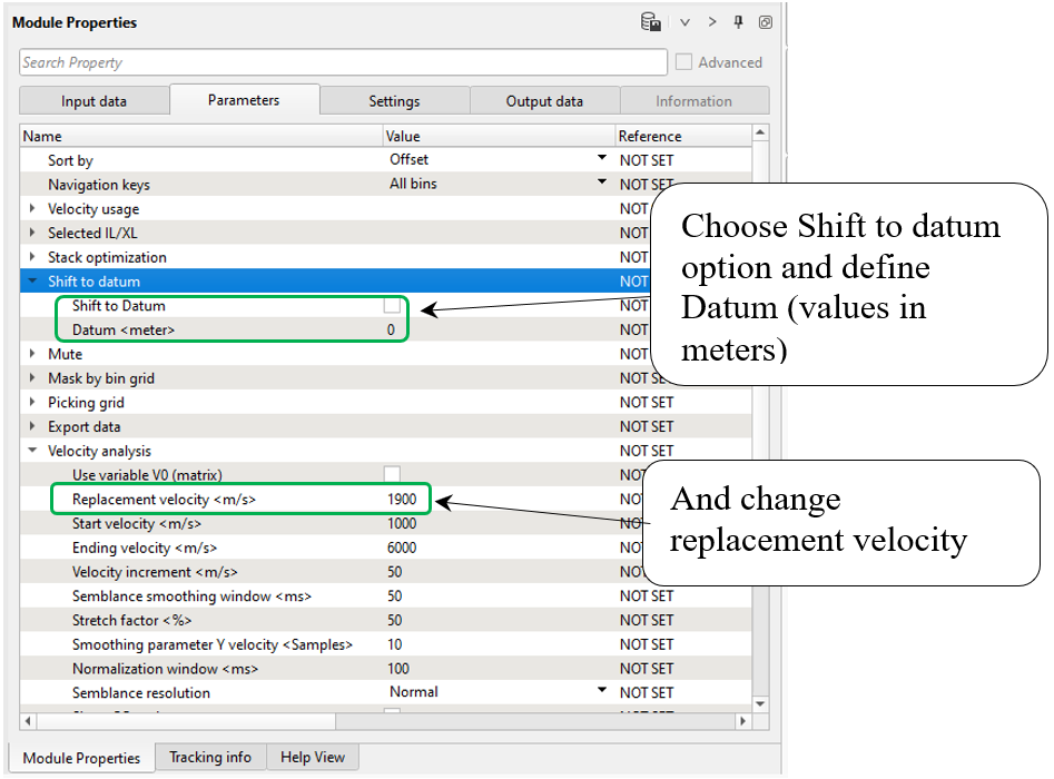
For shifting seismic data from topography on constant datum you should change the following parameters:
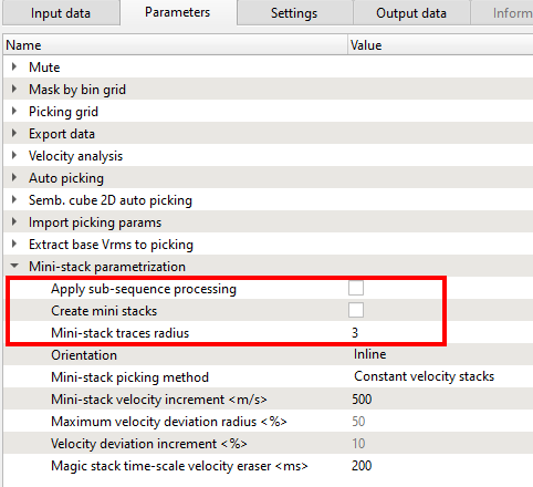
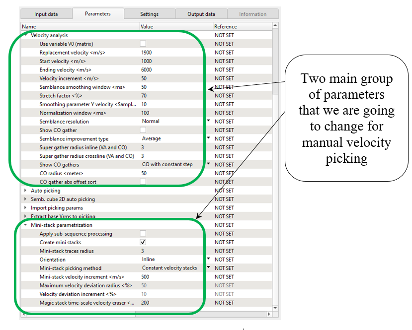
Mini-stack parametrization:
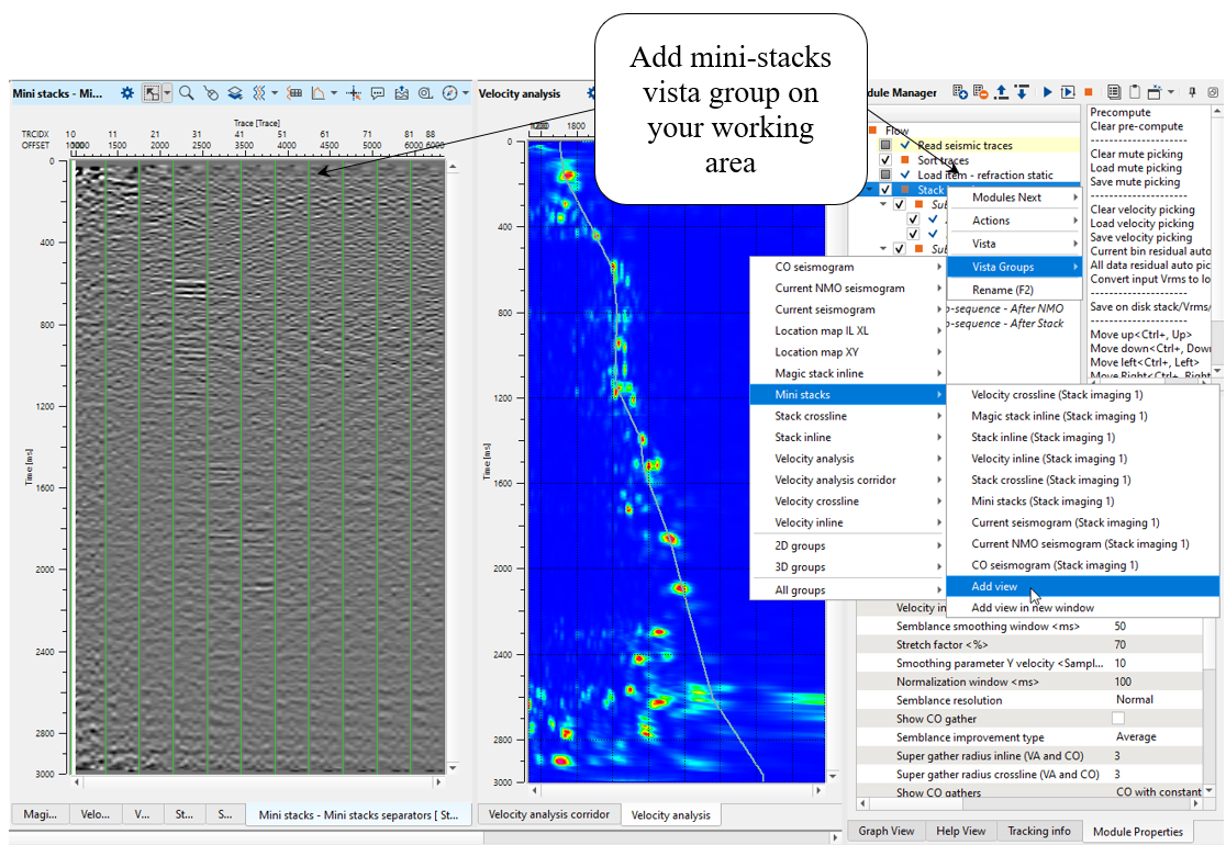
Mini-stacks are also knows as CVS (Common Velocity Stacks). These are very useful in helping the user to get an idea about the overall velocity range and it's trend. There are few parameters needs to be filled to create these Mini-stacks in g-Platform. By default, the Mini-stacks display is not available in Vista Groups-> 2D groups or 3D groups. The user must separately add them.
------------------------------------------------------------------------------------------------------------------------------------------------------
![]() Velocity picking within the Stack Imaging module is not corrected to final datum. In g-Platform, we pick velocities on the topography and shift it to the final datum if necessary. In that case, we should use Shift to datum option inside the Parameters tab. Also we can perform this task by adding the Shift to datum module under the Sub-sequence - After stack. The velocities are still at Topography. Only the stack shifted to Final datum.
Velocity picking within the Stack Imaging module is not corrected to final datum. In g-Platform, we pick velocities on the topography and shift it to the final datum if necessary. In that case, we should use Shift to datum option inside the Parameters tab. Also we can perform this task by adding the Shift to datum module under the Sub-sequence - After stack. The velocities are still at Topography. Only the stack shifted to Final datum.
![]() During NMO application, the source and receiver elevation statics are calculated automatically by shifting to CMP (Bin) elevation, and applied to the seismic trace
During NMO application, the source and receiver elevation statics are calculated automatically by shifting to CMP (Bin) elevation, and applied to the seismic trace
-----------------------------------------------------------------------------------------------------------------------------------------------------
So, now look though the parameters that we are going to change. Pay attention on super-gathers and mini-stacks: increase number of CMP gathers for semblance and turn on mini-stacks calculation:
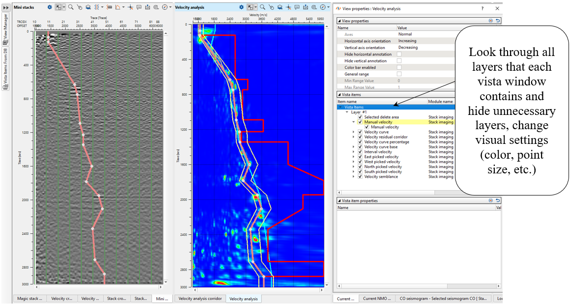
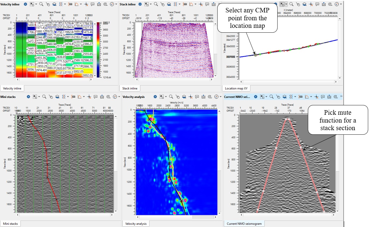
Open all vista groups and mini-stacks (do it manually, by default it is not in vista groups). Look at the picture below, you should have something similar, it is default visual setting and windows configuration. Make some changes of visual settings, open view properties of Velocity analysis and Mini-stacks: change layers visibility, colors, points size, etc.
Perform velocity picking on current CMP point: pick on semblance or mini-stacks section. To pick velocities, click on the velocity analysis window panel. It will come up with three lines. The two yellow lines are basically the Velocity corridor and the middle line is the Current velocity pick trend (input velocity 100%). Once we start picking the velocities, a red line appears which is the Interval velocity.
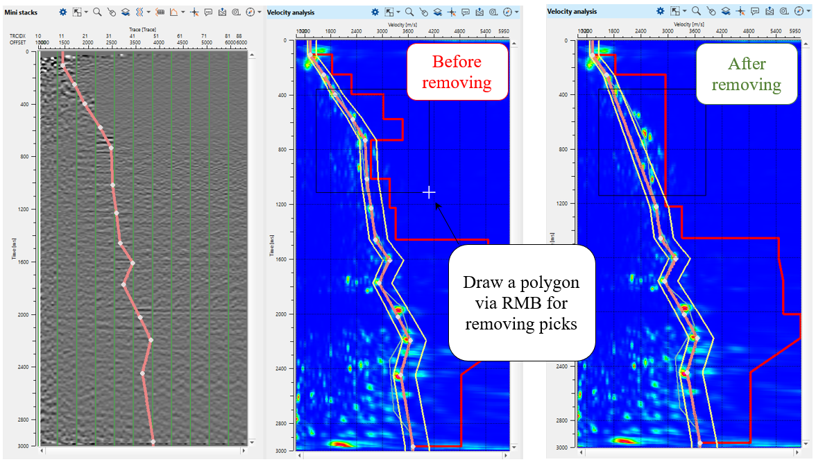
For removing any picks any bad picks: should hold RMB and draw a polygon. Whatever is falling inside the polygon will be removed.
For editing any picks: click on the area near a particular pick and it will be moved to a new position:
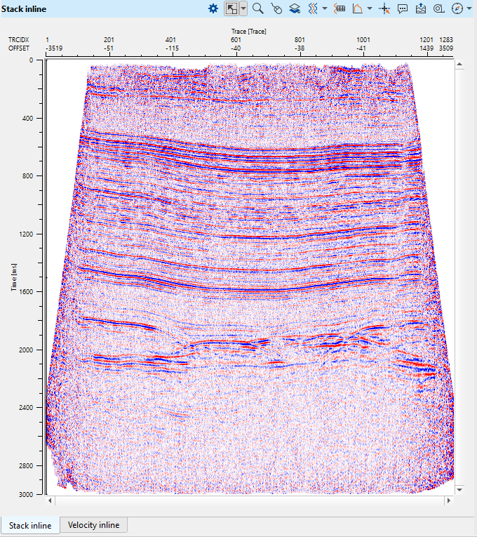
Configure all vista windows as you prefer and make velocity picking for several CMP points. You can remove some of the extra vista windows and use them if necessary. For example, there is a list of vista windows that we can use for current 2D velocity analysis: Velocity inline, Stack inline, Location map, Mini stacks, Velocity analysis, Current NMO seismogram. As we are picking more locations, Velocity inline keeps updating however we still can't see the Stack inline. To generate the Stack inline, we should execute the Stack Imaging module either by double clicking on Stack Imaging module or press the Execute module ![]() icon.
icon.
Depending on the user's parameters, we can pick the velocities either randomly by selecting on the location map or as per the picking grid which was defined in the Parameters tab. To move left, right, up & down, one can look at the action items menu and use the short cuts to move around.
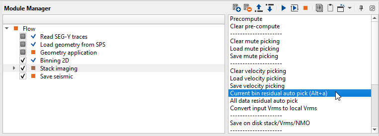
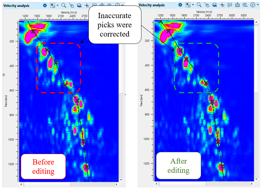
Since we have picked stacking velocity manually, there is an option for performing residual correction. For example, if some pick was picked inaccurate and should be corrected. Residual picking is NOT auto-picking mode. Go to the Action items (menu) and choose the option Current bin residual autopick for the current bin position only. Then use All data residual auto pick option for the entire data:
Press the Execute module ![]() icon again. Now we have a new stack, velocity and mute function for stack.
icon again. Now we have a new stack, velocity and mute function for stack.
Optionally, we can save resulting stack, velocity and NMO gathers in SEGY format on a disk: choose the option Save on disk stack/Vrms/NMO from the action menu.
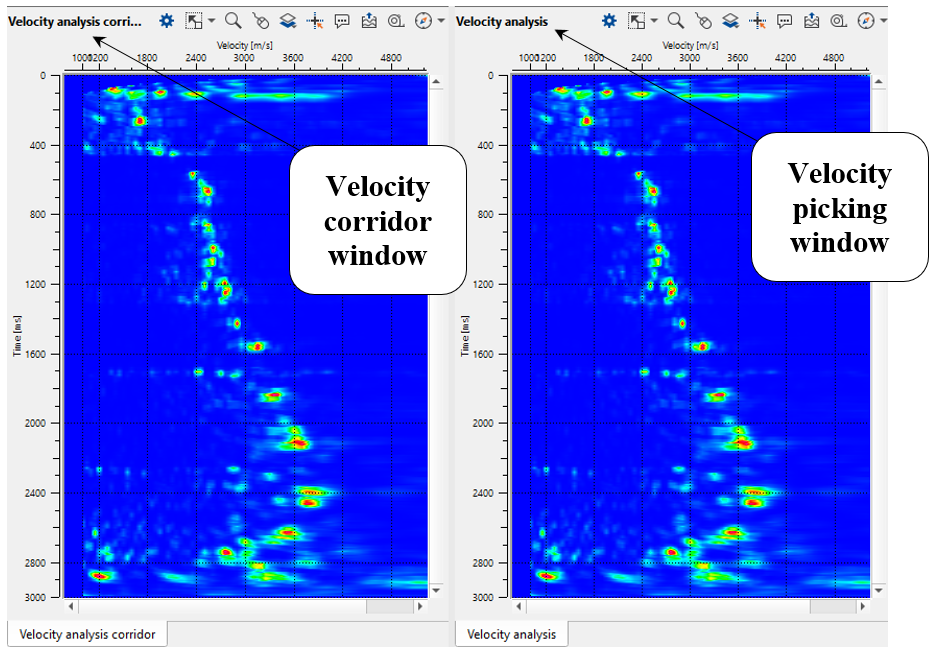
Now it will be added to the existing other Vista items. Velocity analysis and Velocity analysis corridor both look a like however the functioning of each one of them is slightly different. We use Velocity analysis for picking the velocity manually whereas in Velocity analysis corridor, we use it for picking the velocity corridor which is mandatory for picking the velocities automatically.
To pick the velocity corridor, define auto-picking and corridor semblance parameters. Click on any where on the Stack inline/Velocity inline or Location map and look at Velocity analysis window and Velocity analysis corridor:
Next, go to the Velocity analysis corridor and choose Manual velocity corridor option from the control item ![]() icon. To pick the corridor, just click on the Velocity analysis corridor with MB1 or left mouse button. You will observe 3 lines, it is velocity corridor (left limit, center and right limit). To adjust the corridor picks, we can hold MB1 or LMB and drag the green points wherever we want. Pick velocity corridor by going through different CMP points and check. If the corridor is outside of the velocity semblance we can either pick a new velocity corridor at that particular CMP location or adjust the corridor. We need to pick a skeleton of velocity corridor for auto-picking. Corridor for each CMP point will be automatically interpolated between the two existing corridor picks.
icon. To pick the corridor, just click on the Velocity analysis corridor with MB1 or left mouse button. You will observe 3 lines, it is velocity corridor (left limit, center and right limit). To adjust the corridor picks, we can hold MB1 or LMB and drag the green points wherever we want. Pick velocity corridor by going through different CMP points and check. If the corridor is outside of the velocity semblance we can either pick a new velocity corridor at that particular CMP location or adjust the corridor. We need to pick a skeleton of velocity corridor for auto-picking. Corridor for each CMP point will be automatically interpolated between the two existing corridor picks.
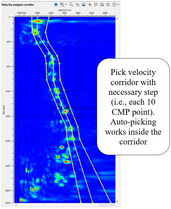
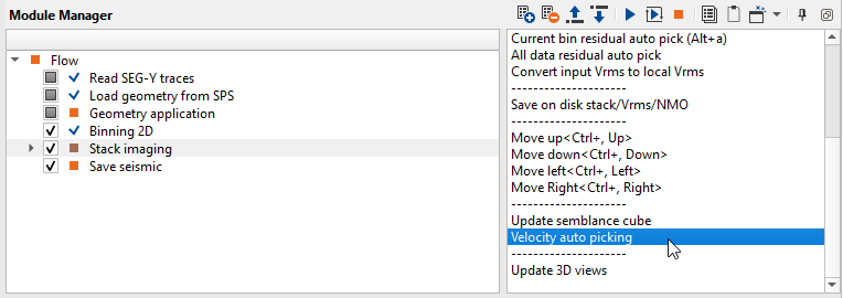
Once we have picked velocity skeleton, now it is time for velocity auto picking. To do that, click on Velocity auto picking action item as shown below:
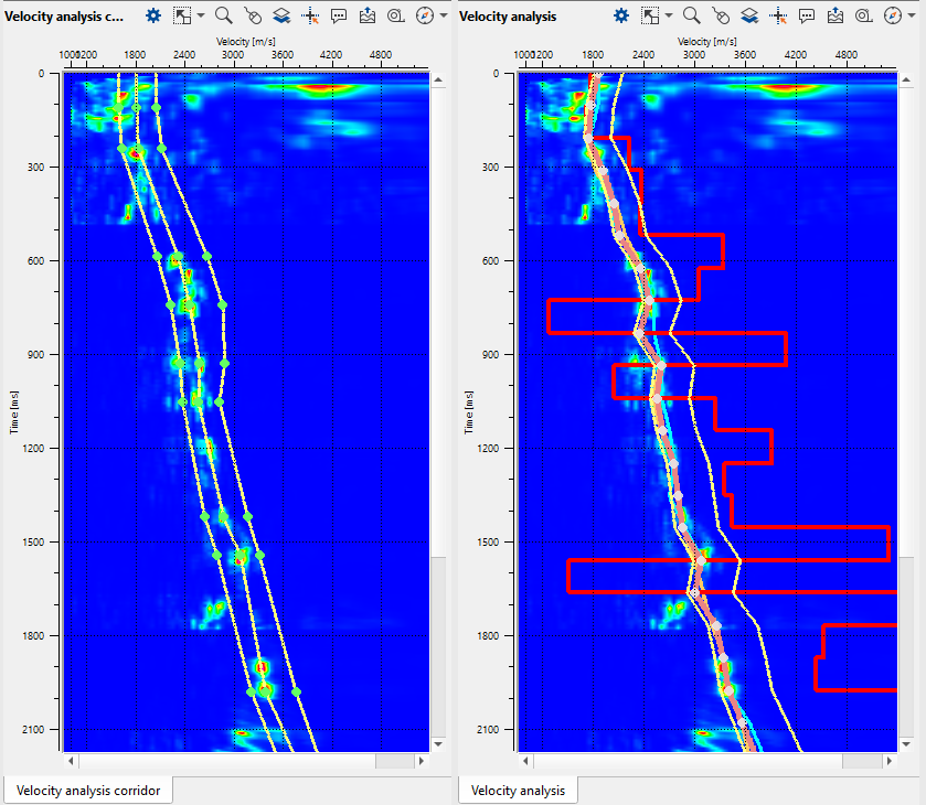
Velocity analysis corridor and Velocity analysis windows after auto-picking process:
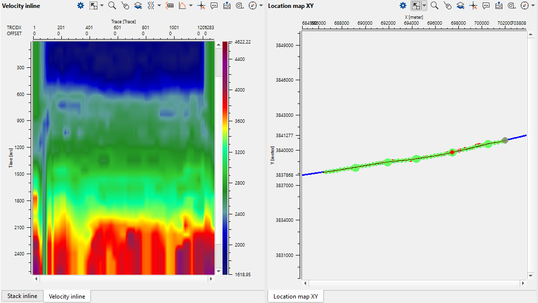
Velocity model and Location map. Velocity is quite sharp, so we will apply smoothing and editing edge effects (caused by low fold):
Press the Execute module ![]() icon to rebuild a stack.
icon to rebuild a stack.
.
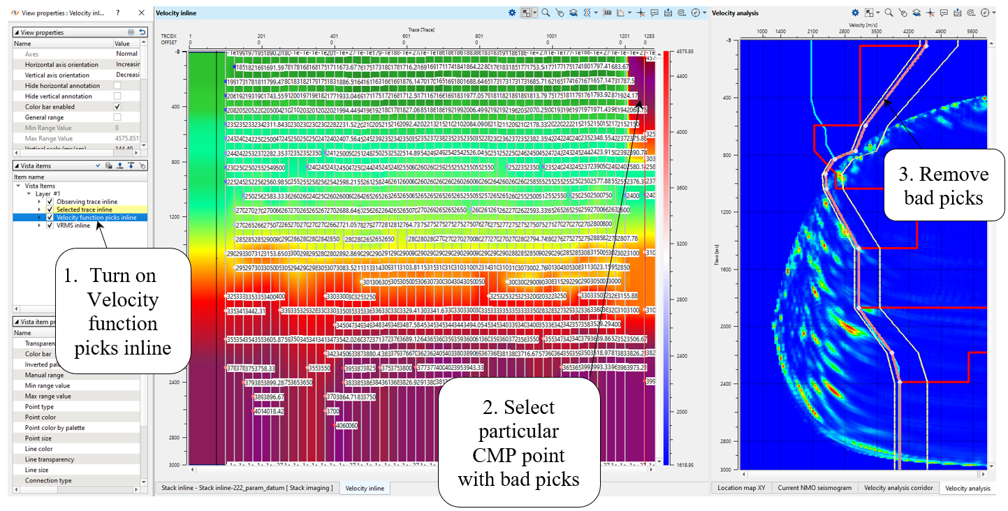
Velocity editing:
We need to correct edges, open velocity and spectrum windows. Go to the particular CMP point by clicking on picked CMP trace on the velocity stack section (Velocity inline), and correct or remove bad picks:
 If you have any questions, please send an e-mail to: support@geomage.com