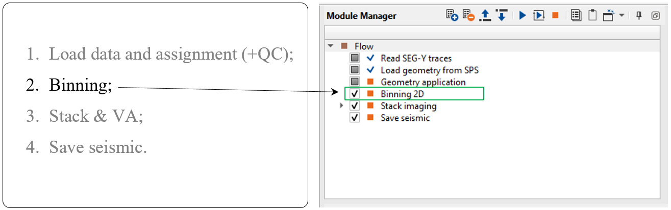
The next geometry step is binning - creating bin, inline, crossline numbers and its coordinates, fold and azimuth calculation, floating datum defining (for further processing).
There are two modules: Binning2D and Binning3D for 2D and 3D seismic acquisitions. Let's have a look at 2D case:
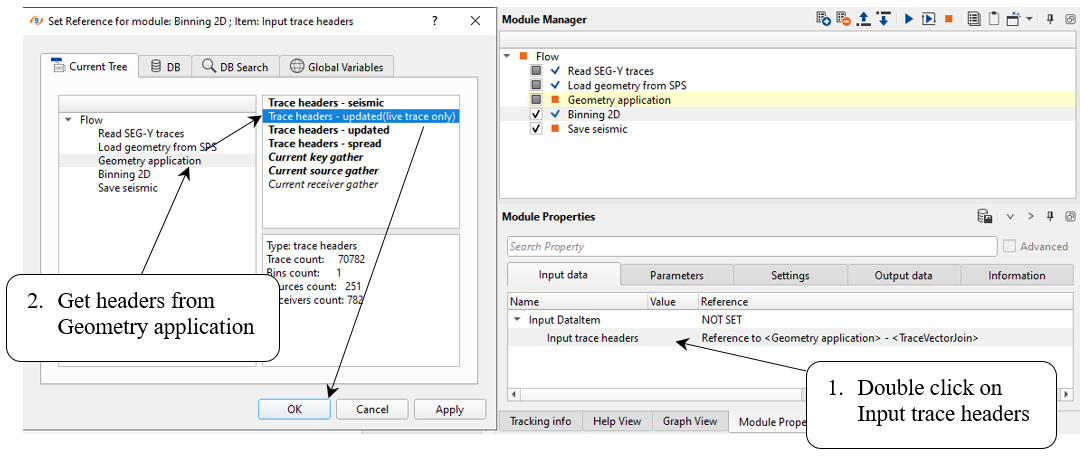
Now we have geometry information from SPS files inside seismic trace headers, so the last step is to calculate slalom line for binning 2D and update CMP numbers and coordinates.
This module creates geometry for 2D seismic data set where traces are grouped together by their sub-surface positions into common midpoints (CMP). For visual quality control, the module creates several vista views for binning quality control.
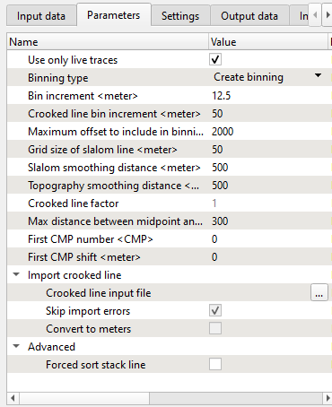
The binning process consists of the following steps:
1. Filter midpoints by maximum trace offset value. Only midpoints that have an offset less than or equal to a user specified value will be used.
2. Build the grid. A direct line is drawn from the first source/receiver location to the last source/receiver location. The line is then divided into segments, with each segment being the grid size of the slalom line as defined by the user.
3. Build the slalom line. The set of midpoints are divided into groups using the grid increment previously defined. The center point of each midpoint group is determined, these points are connected and become the slalom line.
4. Smooth the slalom line by using the slalom smooth parameter and the topography smooth window parameter.
5. Build a crooked line using the crooked line increment parameter. The first point of the crooked line is the first source/receiver bin center point and the last point of the crooked line is the last source/receiver center point location.
6. Build a stack line using the stack line step parameter. This is the CMP spacing. The first point of the stack line is the first center point and the last stack point is the last center point. The user assigns the number of the first CMP and these will then increment by one
7. Filter midpoints with a maximum distance between the MP and CMP point parameter.
Set up all necessary module's parameters and launch the job, check results:
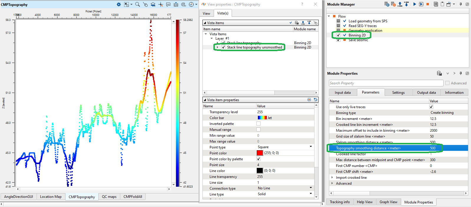
Add all vista group in a new window. Look at CMPTompography window, there are two elevation lines: original relief and smoothed one. Smoothed elevation it is a float datum that you will use on the further processing steps, for example velocity estimation, etc. More detailed review of datum planes will be in the chapter Datum planes.
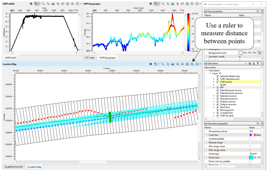
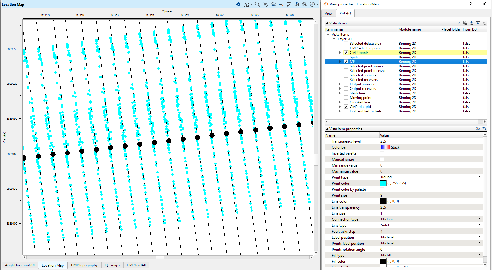
Location map has many layers with different information that geophysicist can use for binning parametrization: bin size, CMP spreading, bin location, and so on:
One very important feature of this module is floating datum creating:
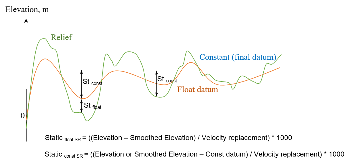
Land seismic acquisition requires to use seismic datum plane (DP), because relief is variable and it may produce incorrect velocity estimation. There are two common types of datum planes: constant and float. Float datum plane usually is used in case of high variations in elevations, so it means we can't use a constant datum due to the fact that velocity estimation should be accurate. But if we use a constant datum plane in case of big fluctuation of topography we may loose details in RMS velocity during NMO spectrum analysis. Float datum is a smooth tomography of sources and receivers elevations (smooth aperture usually is 500-1500m). Therefore, if we have quite flat relief it is reasonable to use constant datum plane which is usually just an average level of elevations. Constant datum plane is a level that may be average elevation or be above the highest elevation. Static corrections move data to the datum with using replacement velocity (Vrep), and it is an acoustic velocity value used during processing for static calculation in order to bring data to a desired level (const of float).
A few basic points:
•Binning 2D/3D modules create a smooth topography (float datum) and save it into BIN_ELEV header;
•After NMO-correction seismic data will be shifted to the floating datum (NMO module calculates and applies static shift automatically);
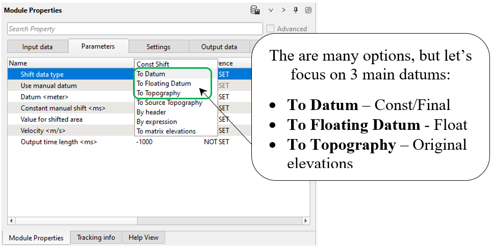
•Shift data module moves seismic data to any datum: constant/final, floating or topography;
•Read SEG-Y traces module does have Data datum parameter. We must set datum correctly, for example if data is on topography, set Topography.
g-Platform system provides all necessary options for datum planes:
•Topography (relief);
•Float (smoothed topography);
•Final (constant).
When you read SEG-Y file, there is an option for defining datum plane, look at the parameters of Read SEG-Y traces module and find Data datum:
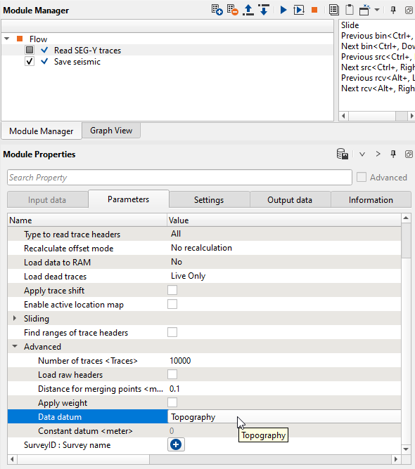
If the input seismic data set is on topography we should choose Topography option.
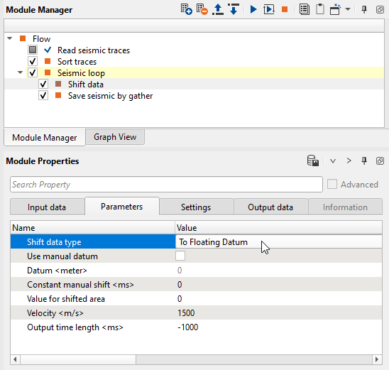
During geometry assignment process, we can create a smoothed topography which is actually representation of the floating datum. Values of floating datum are written into trace headers and we can use it for static calculation via Shift data module. In case of shifting data to the float datum we need to choose To Floating Datum option and define replacement velocity - Velocity <m/s>. Look at example of workflow:
Current chapter is about theoretical aspects of datum planes in g-Platform and we are not going to apply any static correction here.
--------------------------------------------------------------------------------------------------------------------------------------------------------
![]() We will use topography datum plane before NMO correction in this 2D land tutorial.
We will use topography datum plane before NMO correction in this 2D land tutorial.
After NMO-correction the seismic data will be on floating datum.
Module NMO calculate static correction and apply it automatically. The NMO module uses following
headers for calculation: BIN_ELEV, SOURCE_ELEV, RECEIVER_ELEV, replacement velocity is
defined in the module's parameters. SOURCE_DATUM and RECEIVER_DATUM headers will be updated.
In Binning 2D module, we provided created a smoothing topography which is representation of the floating datum.
---------------------------------------------------------------------------------------------------------------------------------------------------------
Shift data allows to use various types of datum planes, i.e. it shifts seismic data to the desired level: topography, float, constant/final.
Parameters:
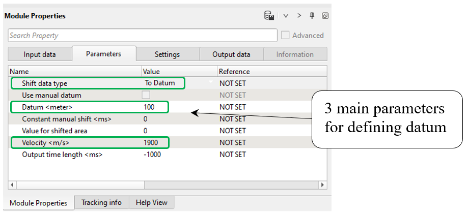
First test with option To Datum, so choose this one, define datum parameters:
•Shift data type = To Datum (constant/final)
•Datum = 100 m (constant level)
•Velocity = 1900 m/s (replacement velocity)
-------------------------------------------------------------------------------------------------------------------------
![]() Normally, don't use Use manual datum option. This is an auxiliary parameters for changing
Normally, don't use Use manual datum option. This is an auxiliary parameters for changing
datum value of the input data.
-------------------------------------------------------------------------------------------------------------------------
 If you have any questions, please send an e-mail to: support@geomage.com