In g-Space, the geological modeling workflow allows users to create detailed structural models of subsurface geology.
To start navigate to the Reservoir bar and click Create 3D geological model.

This process is streamlined through a user-friendly wizard that guides users through defining essential geological features such as layers and faults.
The General tab, currently displayed, handles layer definitions.
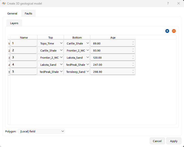
Layers Section allows the user to define the stratigraphic layers within the 3D geological model. Each row represents a layer in the model, with the following parameters:
•Name: The layer's identifier, which can be adjusted manually.
•Top: The geological horizon that defines the top of the layer. Users can choose a predefined depth map.
•Bottom: The geological horizon that defines the bottom of the layer.
•Age: This column allows for defining the geological age of the layer according to Stratigraphy in the Data manager.
The "+" and "-" buttons on the right top of the wizard allows users to add and remove layers.
Notes
Ensure that the depth maps are derived from reliable, high-quality data, as this forms the basis of your structural model. Check for consistency between seismic-derived depth maps and well tops to avoid discrepancies in your model.
Ensure that the faults are accurately interpreted from high-quality seismic data and validated against well data or geological maps. Faults should be checked for continuity and consistency across different horizons to prevent misalignment in the model. Pay attention to fault throw and displacement, ensuring that they align with geological observations.
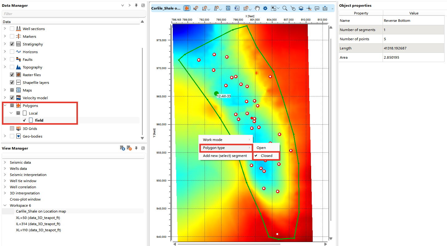
The dropdown at the bottom enables users to select a Polygon to define the spatial extent of the model.
When creating a polygon to define the modeling area, ensure that the polygon type is set to Closed by pressing Alt + right-clicking.
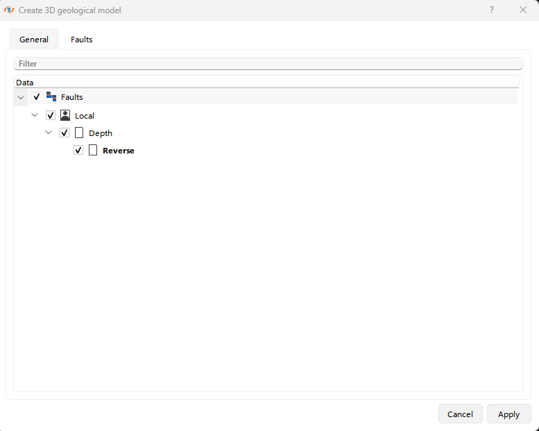
The Faults tab allows the user to select faults to build a geological model.
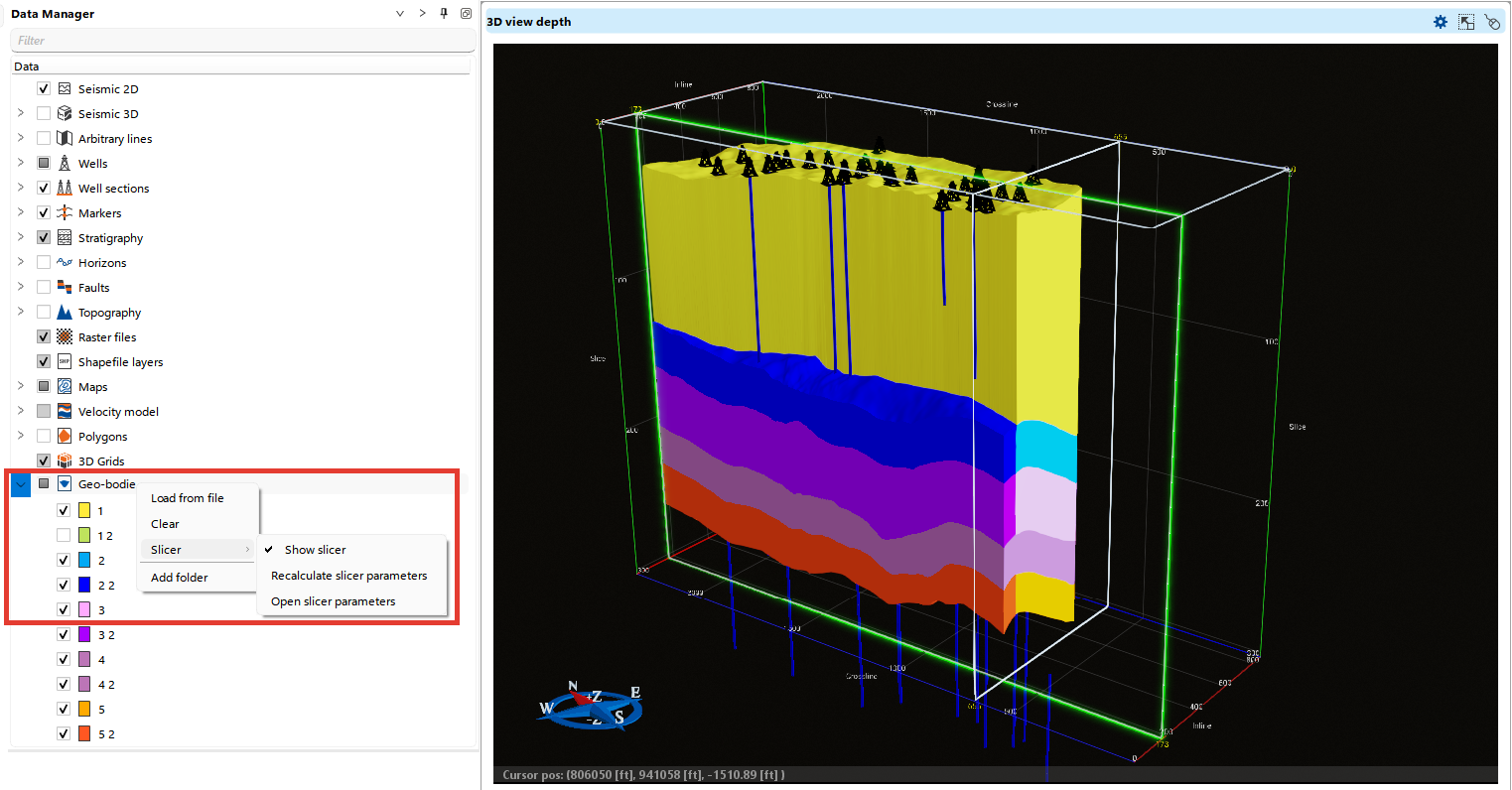
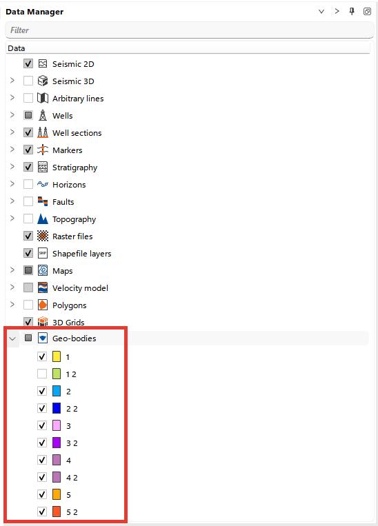
You can see the resulting model in the Geo-bodies folder in the Data Manager.
For each layer, an object will be created automatically. If the layer is divided by a fault, multiple objects with a numeric suffix will be generated, as shown in the example below, where each layer has an object with its layer number (e.g., 1), along with additional objects for faulted segments (e.g., 1.2). To rename any object, simply right-click on it and select Rename from the menu.
You can visualize the model in 3D view, as well as in sections. Each object can be visualized individually via the Data Manager.
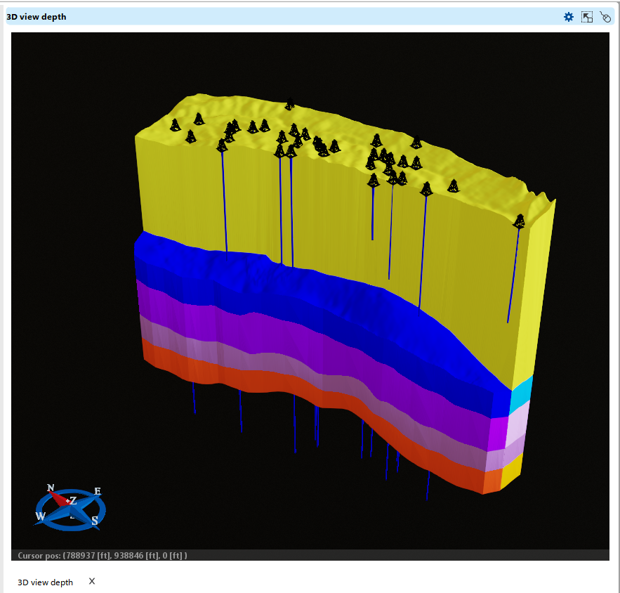
The Slicer mode, accessible by right-clicking on the Geo-bodies folder in the Data Manager, allows you to interactively view geomodel sections in 3D. The active slicing plane is highlighted in light green, as shown in the example figure, where the plane is oriented along the field.