Map creating
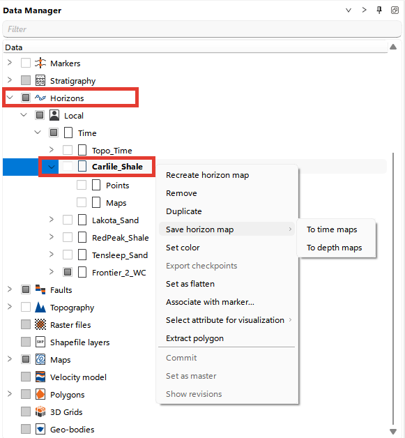
The Horizons folder in the Data Manager stores data as Points and Maps. When a horizon is picked, only points are created initially. To generate a map, right-click on the horizon and choose Recreate horizon map. You can then save the generated map to the Maps folder by selecting Save horizon map from the Horizons folder and choosing either the time or depth scale, depending on the type of data you are working with. To convert time horizons to depth maps, a velocity model must be present in the project. By default, the active velocity model is used for this conversion.
The user can set the mapping settings in the Modelling ribbon tab, in the Map calculator group, by clicking the Settings button, as well as in the Module Properties. The interpolation parameters are described in Modelling.
To convert time maps into depth maps and back, a Velocity model must be created in the project. By default, the active Velocity model is used for conversion.
A map can also be built from a horizon, from well markers or from a point set with the Map building dialog, which keeps its own set of parameters and saves the result in the Calculated maps folder.
Thickness maps
Thickness maps are stored in the Maps folder of the Data Manager, in a separate folder for each thickness type:
Isochron maps — time thickness between two surfaces in the time domain.
Isochore maps — vertical thickness between two surfaces in the depth domain.
Isopach maps — true stratigraphic thickness, measured perpendicular to the bedding.
To build thickness maps from picked horizons, right-click the Time or Depth node in the Horizons branch of the Data Manager and choose Create thickness maps. The command is available when the domain holds at least two horizons, and each pair of adjacent horizons produces one map. Time horizons produce Isochron maps and depth horizons produce Isochore maps; the map name starts with Isochron_ or Isochore_ and is completed with the names of the two horizons.
For depth horizons the same menu also offers Create isopach maps, which builds the true stratigraphic thickness for each pair of adjacent horizons and saves it in Isopach maps under a name starting with Isopach_.
Maps extracted from a 3D grid zone are stored the same way. In the Extract map dialog, the Map type list offers Isochore map for a depth grid and Isochron map for a time grid, and a depth grid additionally offers Isopach map. The read-only Storage location field shows the folder the result will be saved in, and the map name is built from the grid and zone names, for example Depth_grid_Frontier_Isochore.
The Map Calculator allows users to create new maps by performing calculations using existing map data. To open the Map Calculator, navigate to the Modelling ribbon tab, Map calculator group, and click 
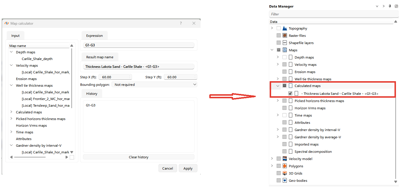
In the Map list, select an input map and click Paste to add it to the expression. Every entry in the list is named after the map type folder that holds the map, followed by the map name. Repeat this for every map the expression uses.
In the Expression field, define the mathematical operation or formula you want to apply to the selected maps. Type the name of the result map at the start of the expression, followed by an equals sign, for example Zone_thickness =. Without a result name the calculation is not started.
Refer to the Trace Headers Math for a description of the available mathematical functions.
Use the Geometry from map list to choose the map whose grid geometry the result adopts. It must be set whenever the expression uses more than one map; with a single map in the expression the geometry of that map is used.
Define the grid step sizes in the Step X and Step Y fields. They set the resolution of the resulting map and are ignored when Geometry from map is set.
If you wish to restrict the calculation to a specific area, select a bounding polygon. If no restriction is needed, leave this as "Not required."
The history of the expressions used in the calculation is displayed for reference, allowing users to track their operations.
Once the expression and the parameters are configured, click ENTER in the keypad to generate the new map. The resulting map will be saved in the Calculated Maps folder in the Data Manager. In the data manager you can drag and drop maps from Calculated Maps to any other folders
In g-Space, users can calculate and visualize attribute maps. A detailed workflow is described in the Seismic Attributes chapter.