Seismic attributes
In g-Space, seismic attributes are tools that extract additional insights from seismic data, offering detailed information about the subsurface.
Seismic attributes can be computed on 2D and 3D data, providing flexibility for seismic volume analysis, horizon interpretation, and fault detection. The attribute settings are configured in the Attributes bar.
First, it's important to note that g-Space offers two methods for calculating attributes: a quick On-fly calculation and a more comprehensive full Calculate attributes for seismic volumes, including spectral decomposition.
How to Generate On-fly calculation Seismic Attributes
- Click on the Attributes icon in the toolbar.
- Set the time window if applicable to the attribute.
- Select the seismic attributes you wish to calculate from the drop-down list. You can choose one or multiple attributes simultaneously.
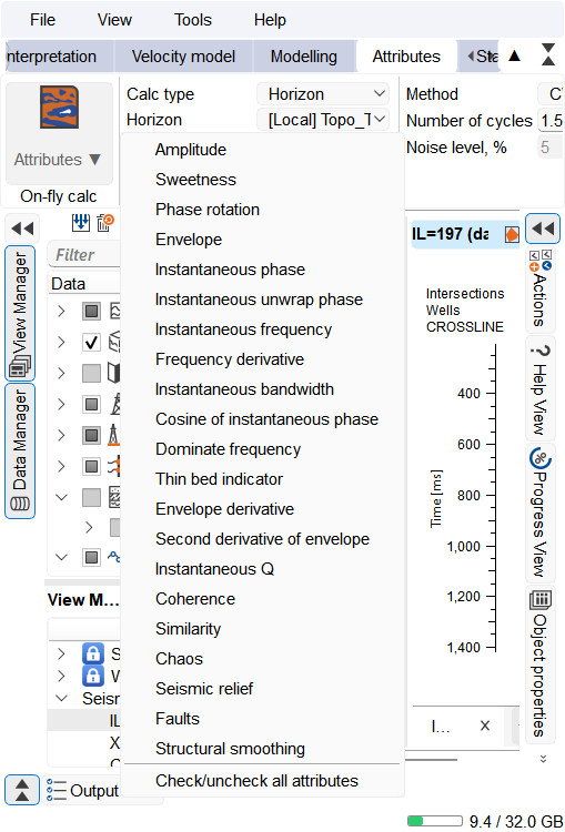
The process takes seconds, the progress can be seen on the right side in the Progress View.

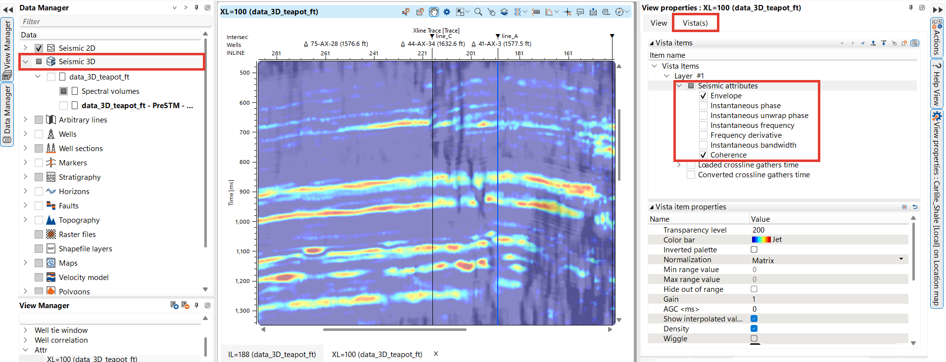
The calculated attribute will be accessible in any seismic view. In the example below, it is shown in the Crossline view. In the Visual Settings panel, users can select one or multiple attributes to display, customize the color palette, adjust transparency, and modify other visualization settings.
How to Generate Volume based Seismic Attributes
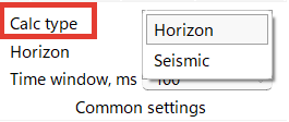
First, navigate to the Attributes bar and, in the Common settings tab, select the calculation type — Horizon or Seismic. Then, go to the Actions section and click Attributes. The Seismic attributes wizard opens, where you can choose seismic data and attributes for calculation.
Click Run to calculate immediately with the current settings, Save to workflow to add those settings to the current workflow without running the calculation, or Close to dismiss the wizard. When you open the saved task from the workflow, its settings are restored; use Save to update the task or Cancel to close without updating it.
There are two options — use Exact along horizon to calculate on a selected surface, or Window to calculate over a specified interval.
Both options share two further settings. Use seismic resolution is selected by default and is available only when exactly one 3D volume is selected; when it is on, the attribute map is written directly on the seismic bin grid instead of being interpolated. Polygon lists the polygons of the project and is set to No Polygon by default; selecting a polygon limits the resulting attribute map to that area, both for the bin-grid map and for the interpolated map.
For Exact along horizon, select the target surface from the Horizon list. In Time mode, the list includes time horizons and time maps; in Depth mode, it includes depth horizons.
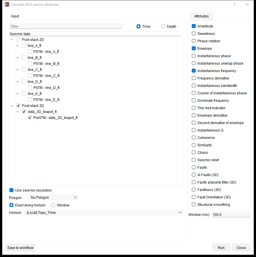
The Window option allows users to calculate seismic attributes over a specified time window relative to a selected horizon or time interval.
There are three options available:
Between time: attributes are calculated over a specific time interval. Users can specify the start and end times (in milliseconds) within the seismic data.
Between horizons: the option calculates attributes between two selected surfaces. Choose the start and end surfaces from the drop-down menus; in Time mode, the lists include time maps as well as time horizons.
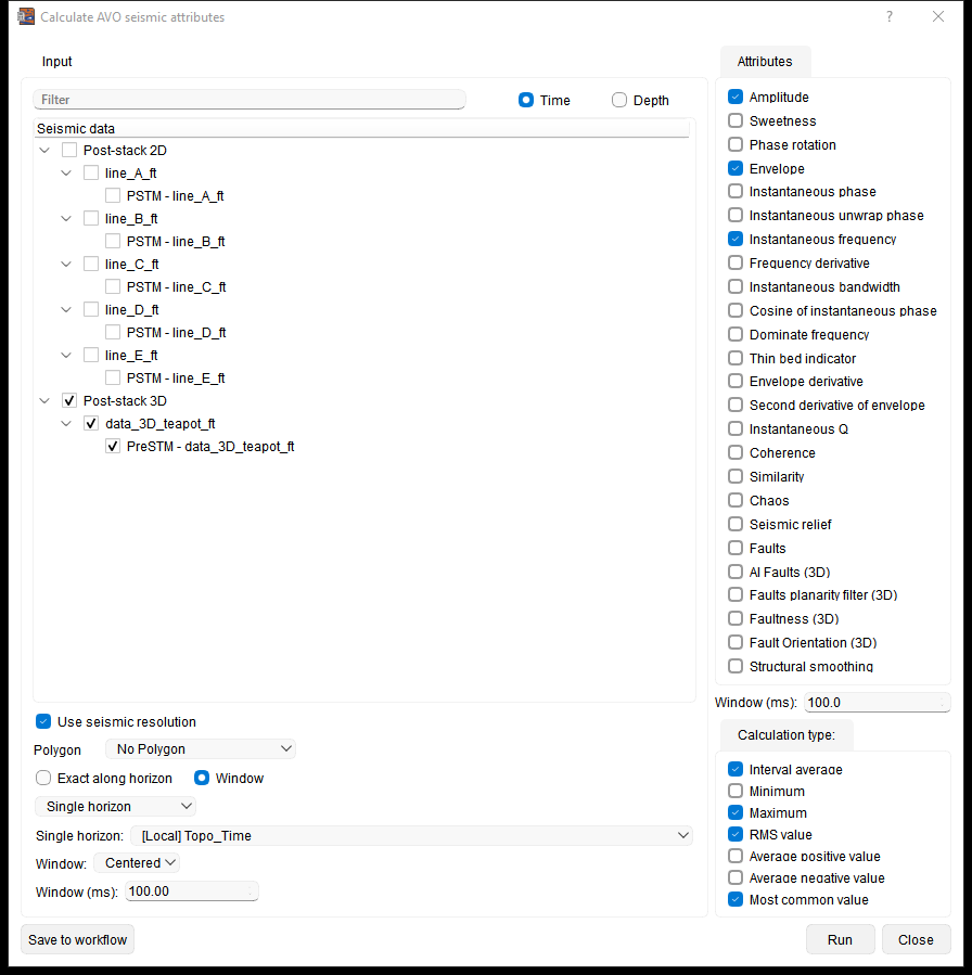
Single horizon: calculates attributes around one selected surface. Choose the surface from the drop-down list; in Time mode, the list includes time maps as well as time horizons. The Window (in milliseconds) determines the time range used to calculate the attributes. The window can be positioned Above, Below, or Centered (with the horizon in the middle, equally above and below) for attribute calculation.
Users can select different statistical operations such as Interval average, RMS value, Maximum, Minimum, Average positive/negative value, or Most common value to be applied within the specified window.
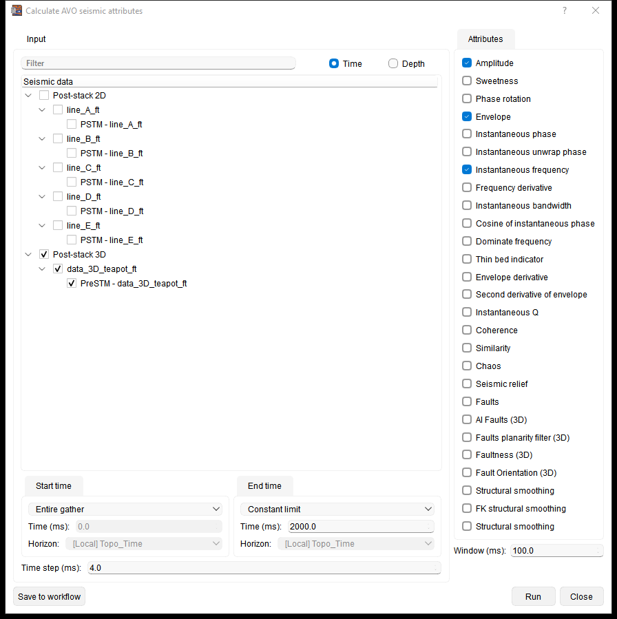
For the Seismic calculation type, use the Start time and End time controls to calculate the entire gather or define a Constant limit or Horizon limit. In Time mode, Horizon limit lists time horizons and time maps; in Depth mode, it lists depth horizons. Set the Time step or Depth step and click Run. Monitor the calculation in the Progress View.
Attribute parameters in the SEG-Y text header:
For the Seismic calculation type each attribute is written to its own SEG-Y file, and the settings used for the calculation are stored in the text header of that file, so a volume can still be traced back to the parameters that produced it after it is reopened or passed on to somebody else. Every file records the attribute name, the time step and the date the file was written (UTC, in YYYY-MM-DD form), plus the time window for attributes that are calculated over a window.
Attributes that have settings of their own also record those settings:
- AI Faults (3D) — inference patch size
- Faults planarity filter (3D) — volume size reduction, edge detection strength and fault continuity
- FK structural smoothing — horizontal sliding window, time window, time taper window, min and max frequency, and the number of Eigen values
- Structural smoothing — sigma inline, sigma crossline, sigma samples and lambda
- Seismic relief — vertical window and pow factor
The entries are placed in the spare lines of the standard 40-line text header (C33, C36, C37, C38 and C40), so the trace-header byte map on the lines above them is preserved; when an attribute has more parameters than there are spare lines, two of them share a line. To read the header, use the Text header view of the seismic data workspace.
View Attributes:
To view the attributes, user should go to Maps section in the Data Manager. Expand the Maps section and click the Attributes section.
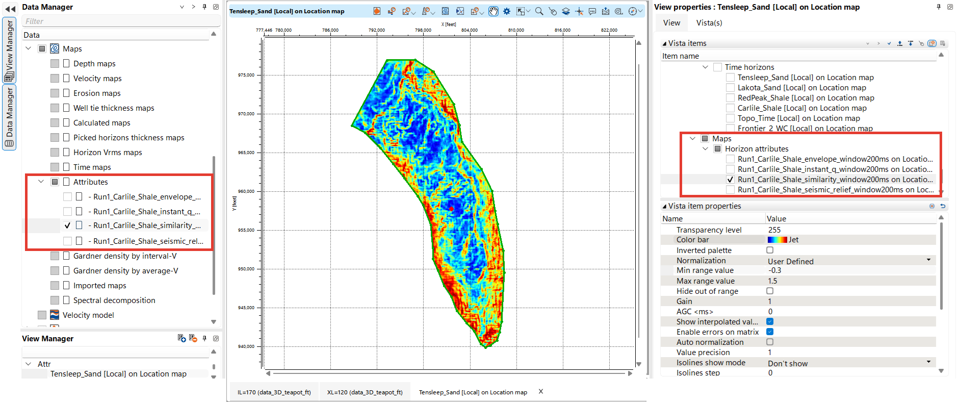
All the calculated attributes should be visible on the Location map.
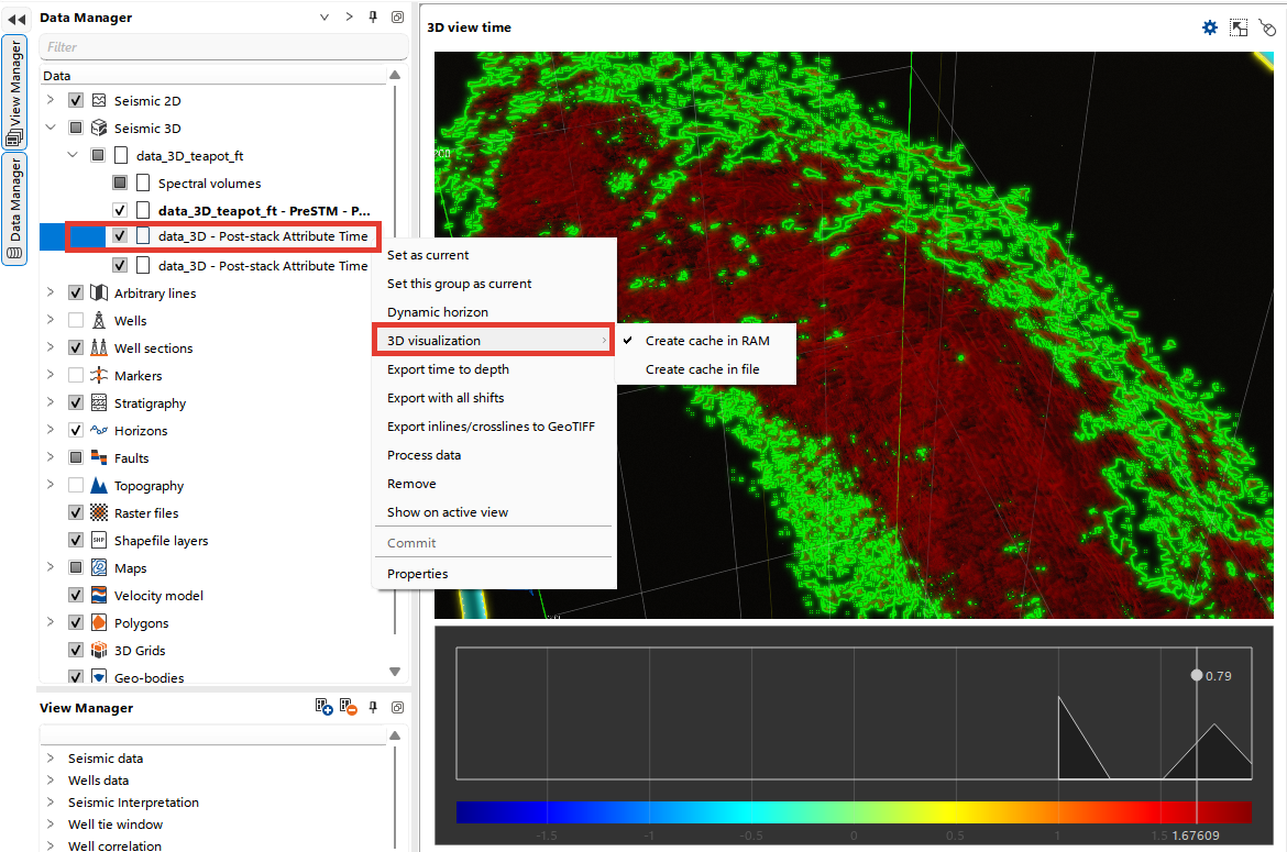
The user can visualize the calculated attribute volumes as any 3D seismic data. To do this, you need to create a cache in RAM or in a file by right-clicking on the calculated attribute volume in the Data Manager. A special volume palette is available in 3D view to customize the visualization of attribute volumes. Adjust the image by dragging the slider along the horizontal and vertical scale.